

 English
 Español
 Deutsch
 中文简体


Product Consultation
Your email address will not be published. Required fields are marked *
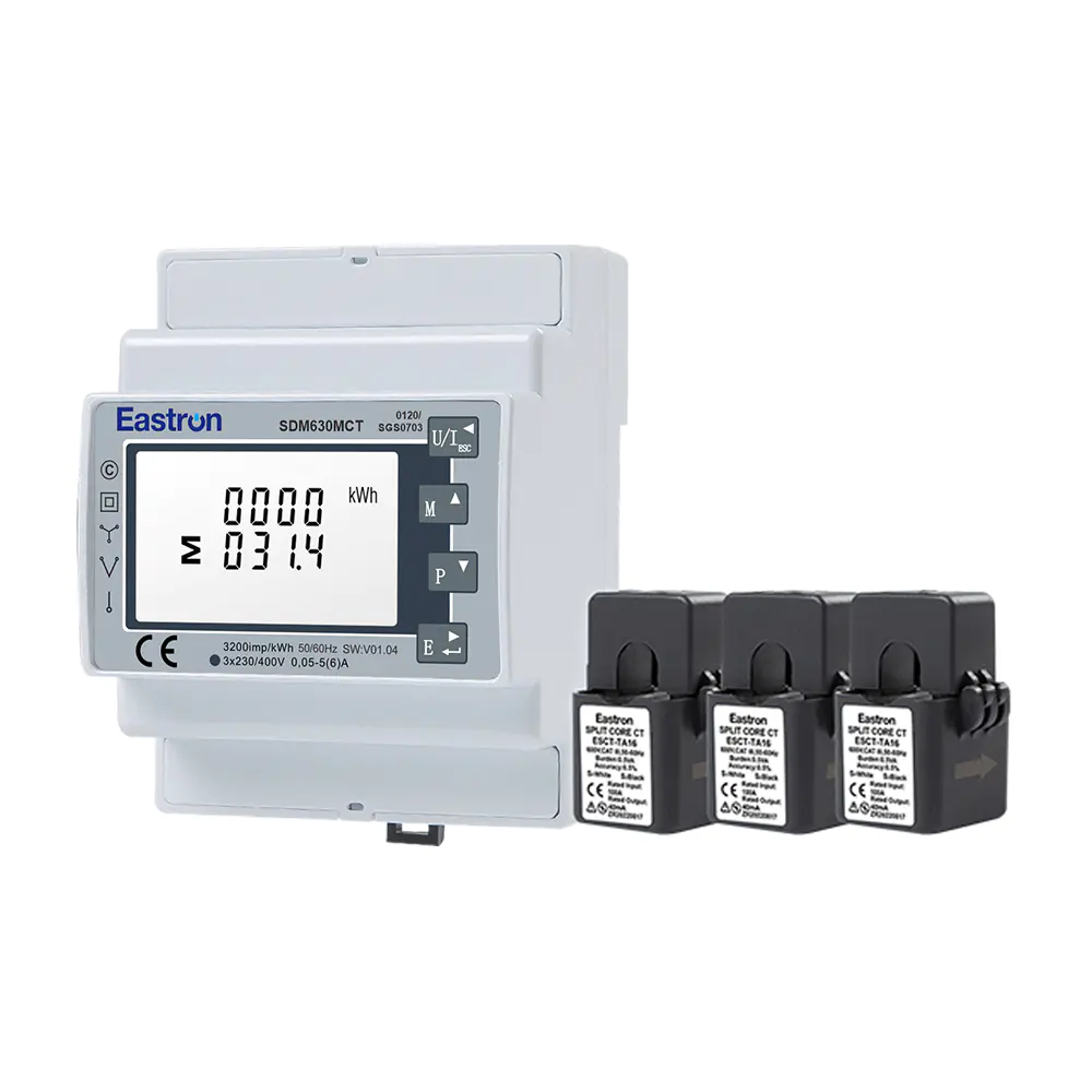
MID/UL CT Type Din Rail Three Phase Multi-function Energy Meter for EV Charging Metering
Nov 24,2022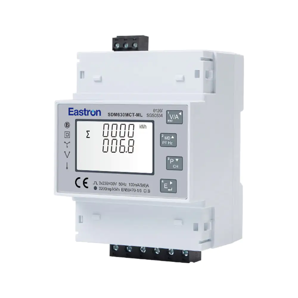
Quad Load Three Phase Multi-function RS485 Energy Meter for Data Center Metering
Aug 03,2022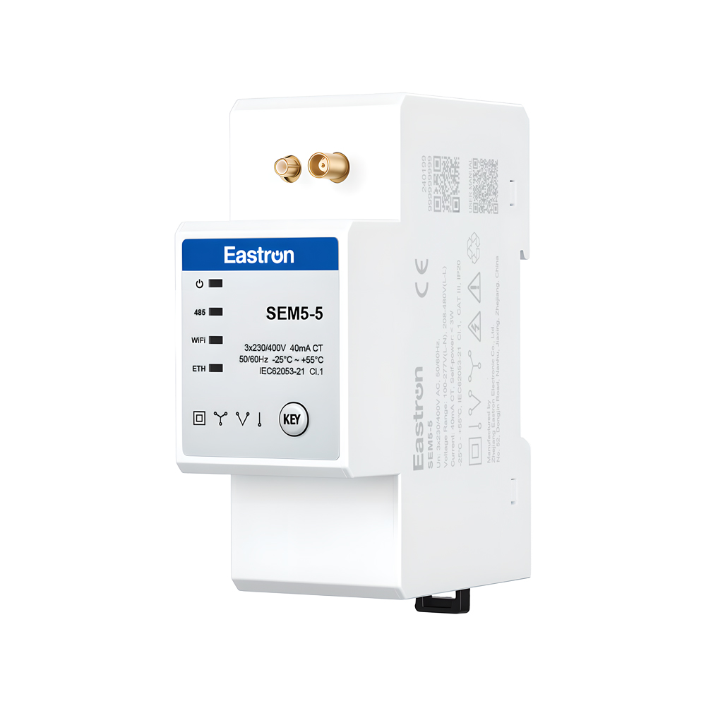
CT Operated Wireless Three Phase Energy Meter for PV Metering
May 30,2025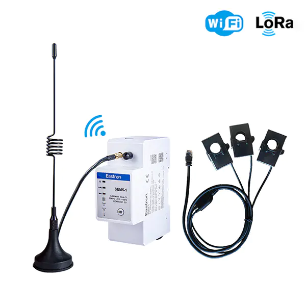
Wifi & LoRa Three Phase Din Rail Energy Meter for PV Metering
Sep 19,2025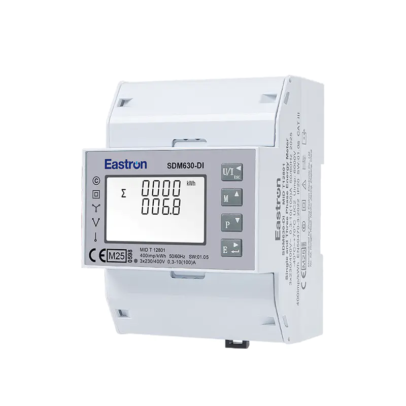
MID & UL Approved Three Phase Din Rail Type Multi-function Energy Meter for EV Charging Metering
Nov 24,2022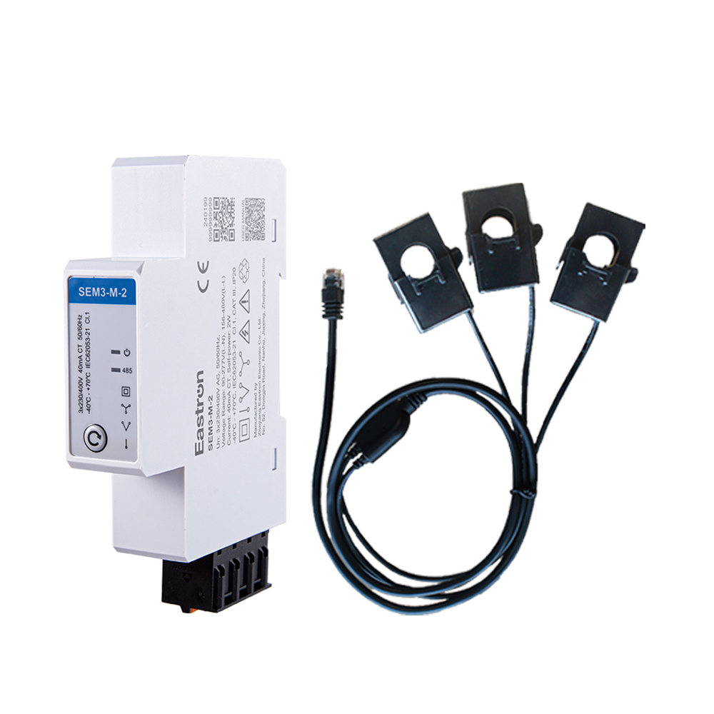
RS485 CT Connection Three Phase Din Rail Energy Meter for PV Metering
May 30,2025Content
Modern electrical systems require more than a simple measurement of consumed kilowatt-hours. Commercial buildings, industrial facilities, renewable-energy installations, electric-vehicle infrastructure, data centers, and distributed equipment increasingly need accurate measurements, remote access, flexible communication, and dependable long-term operation. A meter installed in a switchboard must therefore do more than display voltage and current. It must collect useful power data, communicate with supervisory systems, support different network environments, and remain practical to configure and maintain.
The SDM630MCT-Lora is designed for this type of connected energy-management application. It is a three-phase multifunction energy meter with current-transformer inputs, pulse outputs, and an integrated LoRaWAN communication option. The meter supports three-phase three-wire and three-phase four-wire systems and can measure electrical characteristics such as voltage, current, active power, reactive power, apparent power, power factor, frequency, demand, active energy, and reactive energy.
Its combination of measurement performance, communication flexibility, compact panel installation, and certification options makes it suitable for Internet of Things energy projects. Instead of requiring a separate measurement device, communication gateway, and extensive local wiring for every installation, the meter can serve as a field-level data source for an energy-monitoring platform.
This article examines the product’s operating concept, technical characteristics, communication features, installation value, manufacturing strengths, and advantages over less integrated alternatives. It also explains how the meter can support reliable energy data collection in different commercial and industrial environments.
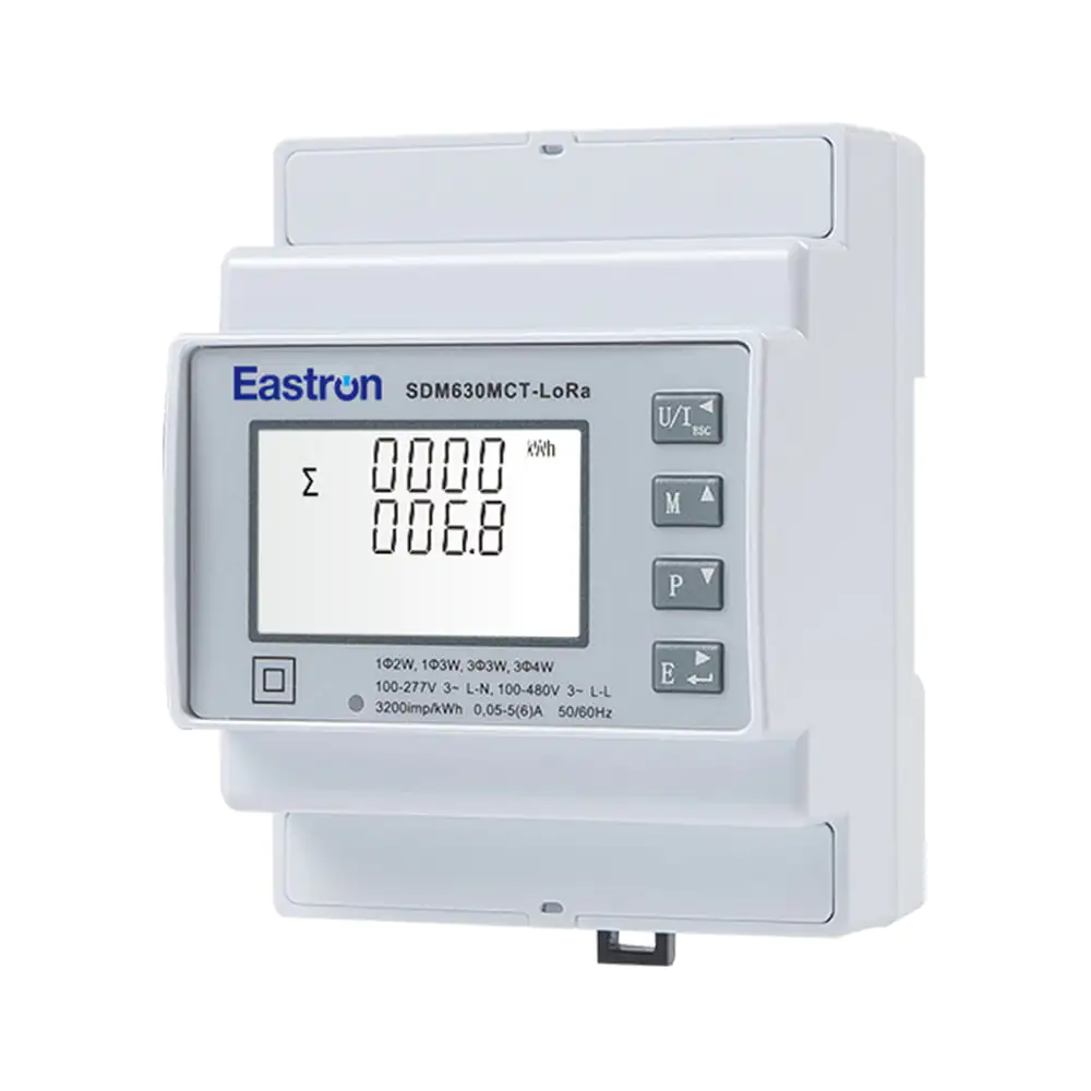
Three Phase LoRaWAN Multi-function Energy Meter for IOT Solutions
Energy costs and electrical reliability are closely related to the quality of available information. A facility cannot effectively identify abnormal consumption, inefficient equipment, poor power factor, phase imbalance, or unexpected demand peaks if the electrical system is monitored only through occasional manual readings. Continuous measurement provides a more complete understanding of how energy is being used.
A multifunction energy meter can collect several categories of information from the same circuit. Basic energy data shows how many kilowatt-hours have been consumed. Instantaneous electrical values reveal what is happening at a specific moment. Demand information helps operators understand the highest loading levels. Power-factor data indicates whether the installation is using electrical capacity efficiently. Voltage and current measurements can help identify operating conditions that may affect equipment performance.
When the measurement device is connected to a communication network, these values can be transferred to a building-management system, industrial monitoring platform, cloud application, or energy dashboard. Operators can then compare different areas of a facility, establish energy baselines, detect changes in operating patterns, and evaluate the results of efficiency projects.
LoRaWAN is particularly useful where long-range wireless communication and low installation complexity are important. Conventional wired communication can be highly reliable, but it may require dedicated cable routes, additional labor, and changes to existing infrastructure. Wireless low-power networks can reduce the amount of communication cabling required between distributed meters and a central collection point.
The SDM630MCT-Lora addresses this need by combining electrical measurement with a built-in LoRaWAN communication function. The result is a meter that can become part of a wider Internet of Things architecture while continuing to provide local measurement and pulse-output capabilities.
The SDM630MCT-Lora is a three-phase multifunction energy meter intended for IoT-oriented energy measurement solutions. It uses external current transformers rather than requiring the full load current to pass directly through the meter. This configuration is valuable for installations where the measured current is too high for direct connection or where the panel design favors CT-based measurement.
The current input can be configured for 1 A or 5 A CT secondary signals. The CT primary setting can be adjusted across a broad range from 1 A to 9999 A, allowing the meter to be matched to different current transformers. Configuration is password protected, which helps prevent unauthorized changes to important metering parameters.
The meter supports 3P3W and 3P4W systems, making it suitable for many common three-phase power-distribution arrangements. Its measurement method is based on RMS values, including harmonics, on three-phase AC systems. This allows the device to provide more meaningful information than a basic meter that reports only limited electrical values.
Depending on the selected version or product configuration, the wider product family can also include RS485 Modbus, M-Bus, dual-power-source, and pulse-output options. The LoRa version provides two pulse outputs together with LoRaWAN communication. This combination enables both wireless data transmission and compatibility with external pulse-counting or control-oriented systems.
| Product characteristic | Specification or capability |
|---|---|
| Measurement system | Three-phase AC measurement with RMS values including harmonics |
| Supported wiring | Three-phase three-wire and three-phase four-wire systems |
| Current connection | External current transformers |
| CT secondary options | 1 A or 5 A |
| CT primary setting | 1 A to 9999 A |
| Voltage rating | 3 × 230/400 VAC |
| Voltage range | 100–277 V AC line-to-neutral; 100–480 V AC line-to-line |
| Communication | LoRaWAN; product family options also include RS485 Modbus and M-Bus |
| Pulse output | Two pulse outputs on the LoRa configuration |
| Active-energy accuracy | Class 0.5 under IEC 62053-21; Class C under EN 50470-3:2022 |
| Reactive-energy accuracy | Class 2 under IEC 62053-23 |
A major advantage of a multifunction meter is the ability to measure several electrical parameters in one device. The SDM630MCT-Lora can be used to monitor voltage, current, frequency, power factor, active power, reactive power, apparent power, active energy, reactive energy, and demand-related values.
Voltage and current are the foundation of electrical monitoring. The meter supports a rated system voltage of 3 × 230/400 VAC. Its stated operating ranges are 100 to 277 V AC line-to-neutral and 100 to 480 V AC line-to-line. These ranges cover many low-voltage three-phase distribution systems used in commercial and industrial facilities.
The voltage measurement accuracy is specified at ±0.2%, while current measurement accuracy is also specified at ±0.2%. Such performance helps provide reliable data for energy analysis, load comparison, and operational review. Current measurement is performed through external CTs, so proper CT selection, orientation, ratio configuration, and installation remain important for achieving the expected system accuracy.
Active power indicates the real electrical power being consumed by equipment. Reactive power represents the component associated with magnetic and electric fields in inductive and capacitive loads. Apparent power expresses the combined electrical loading effect of active and reactive power. Monitoring all three values allows operators to understand both energy consumption and the utilization of electrical capacity.
The stated accuracy is ±0.5% for active power, ±1% for reactive power, and ±0.5% for apparent power over the specified measurement range. Active-energy measurement is rated Class 0.5 under IEC 62053-21 and Class C under EN 50470-3:2022. Reactive-energy measurement is rated Class 2 under IEC 62053-23.
These specifications make the meter suitable for a wide range of submetering and energy-management tasks. It can support tenant billing studies, department-level energy allocation, plant-area monitoring, equipment consumption analysis, and verification of energy-saving measures. For applications requiring formal billing approval or regulated measurement, the applicable certification and installation requirements should always be reviewed for the specific project.
Frequency measurement is specified at ±0.05%, providing a useful indication of supply stability and system operating conditions. Power factor measurement is specified at ±0.01. These values can help facility personnel identify heavily inductive loads, inefficient equipment operation, or changing load characteristics.
Power-factor information is especially useful in installations with motors, transformers, compressors, pumps, and other inductive equipment. A poor power factor can increase current for a given level of active power and may reduce the effective capacity of electrical distribution equipment. By observing power factor together with active and reactive power, operators can determine whether corrective measures such as capacitor banks or equipment optimization may be appropriate.
The meter is designed to measure RMS quantities including harmonics on three-phase AC systems. Harmonic-producing loads may include variable-frequency drives, switched-mode power supplies, information-technology equipment, LED drivers, and power-electronic converters. Although a multifunction energy meter is not a substitute for a dedicated power-quality analyzer in every application, RMS measurement that considers harmonics provides a more realistic representation of electrical conditions than a simplified fundamental-only approach.
This capability is valuable in modern facilities where nonlinear loads are common. It can assist with identifying changes in current demand, understanding heating or loading conditions, and deciding when a more detailed power-quality investigation may be necessary.
The integrated LoRaWAN option is one of the product’s main differentiators. LoRaWAN is a long-range, low-power wireless communication technology designed for distributed sensors and field devices. In an energy-monitoring project, a LoRaWAN meter can send measured values to a network server through a compatible gateway and then forward the data to a monitoring or management application.
The product supports a wide range of regional frequency bands, including EU868, AS923, CN433, CN470, AU915, and US902, among others. Regional frequency selection allows the meter to be matched to the requirements of the target market and local radio regulations. Project engineers should select the appropriate regional version before deployment.
The meter supports an automatic upload mode for sending data without requiring a local operator to retrieve each reading manually. This feature is important when many meters are distributed across a building, campus, factory, or infrastructure site. Centralized collection reduces the time required for routine inspections and makes it possible to compare data from multiple locations.
Upload and download time intervals can be set or adjusted. This gives system integrators the ability to balance reporting frequency, data requirements, network capacity, and energy usage. A site that needs near-real-time operational information may use a shorter interval, while a long-term energy-statistics project may choose a less frequent reporting schedule.
Communication reliability is not determined only by whether a device can transmit a message. A useful monitoring system also needs to recognize whether the message was received and whether a field device has stopped communicating. The product supports confirmation and offline-detection functions, helping the system identify communication interruptions or inactive devices.
Offline detection can be valuable for maintenance teams. If a meter stops reporting because of a power interruption, network problem, antenna issue, or equipment fault, the system can flag the condition for investigation. Early awareness helps prevent long gaps in the energy record.
The automatic-resume mode is designed to help the meter return to normal communication after an interruption. Electrical installations can experience planned shutdowns, maintenance events, temporary network interruptions, and other conditions that interrupt data transmission. Automatic recovery reduces the need for manual intervention and supports more dependable unattended operation.
Data continuity still depends on the complete system, including the meter power supply, network coverage, gateway, server, and application platform. However, an automatic-resume function adds resilience at the field-device level and can simplify operational support.
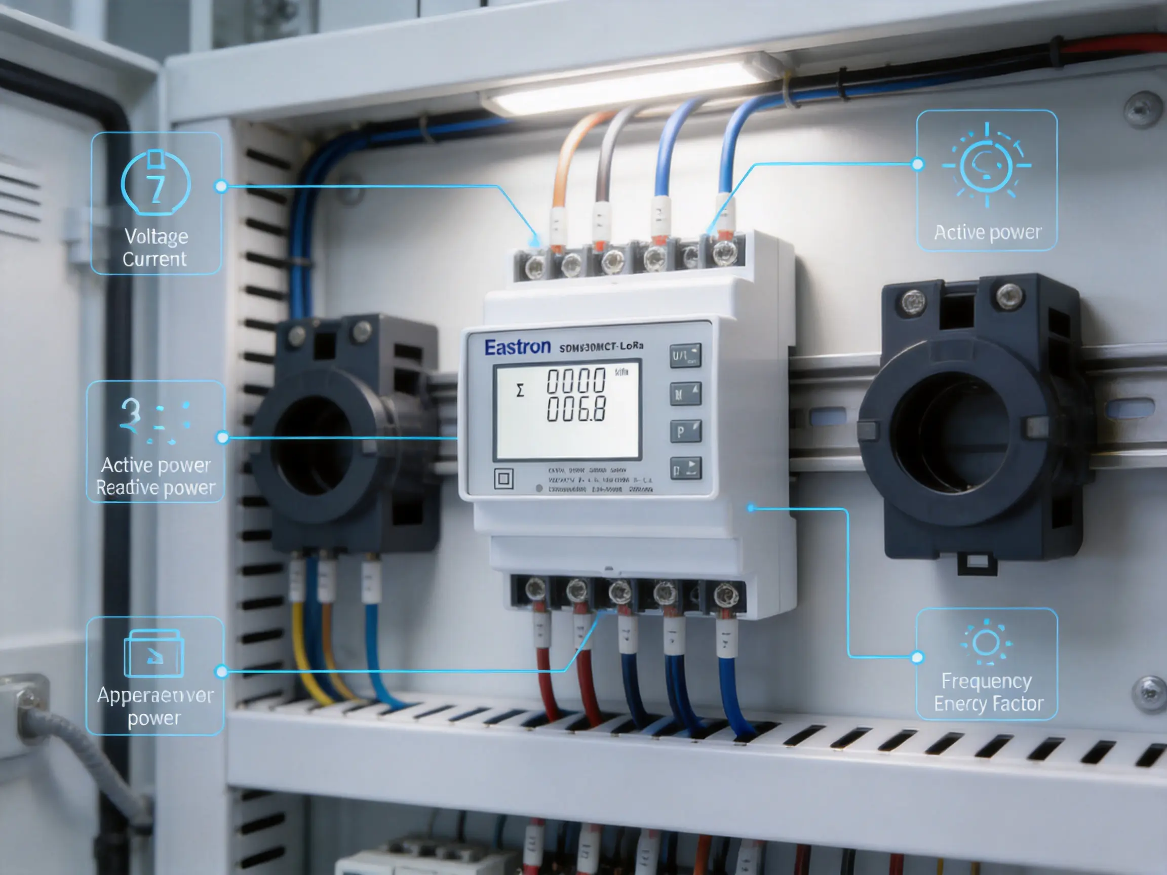
The product offers several practical advantages over basic energy meters or systems assembled from separate components. These advantages are not limited to the communication interface. They also involve installation flexibility, measurement range, information density, and integration potential.
A basic kWh meter may provide only accumulated active energy. That information is useful, but it may not explain why consumption has changed or whether the electrical system is operating efficiently. A multifunction device provides a wider picture by combining energy, power, voltage, current, frequency, power factor, and other values.
Using one multifunction meter can reduce the need for several independent instruments. It can also simplify panel space planning, data mapping, maintenance, and system integration. The result is a more coherent data source for energy dashboards and building-management applications.
Direct-connected meters must be selected according to the maximum current flowing through the device. In larger distribution systems, direct connection may be impractical or may require additional protection and large conductors. CT-based measurement separates the meter from the high-current path and enables measurement of a broad range of loads.
The configurable CT primary range from 1 A to 9999 A allows the product to serve different current levels when matched with suitable transformers. This flexibility is particularly useful for main incomers, production lines, large HVAC systems, generators, and distribution feeders.
RS485 and M-Bus remain valuable communication methods, but they require a wired communication path. In an existing building, installing new communication cable may involve drilling, conduit work, shutdowns, or access to difficult areas. LoRaWAN can reduce those installation obstacles where wireless coverage is suitable.
The wireless option is also useful for geographically distributed measurement points. A facility may have meters in separate electrical rooms, outdoor utility areas, temporary buildings, or locations where communication cables are difficult to route. A LoRaWAN network can provide a common communication layer for these devices.
Support for several LoRa frequency bands helps equipment suppliers and system integrators address projects in multiple regions. Rather than designing a completely different metering concept for every market, a common product platform can be adapted through the appropriate regional communication version and local system configuration.
Remote communication does not eliminate the value of local access. Maintenance personnel may still need to inspect the meter at the panel, verify wiring, or compare displayed information with data shown in a supervisory system. The product combines field-level measurement with communication features and pulse outputs, providing multiple ways to use its data.
This layered approach is valuable in projects where the primary system is digital but local technicians require direct access during commissioning and service.
Although the SDM630MCT-Lora is focused on LoRaWAN communication, the related product configurations demonstrate a broader communication strategy. Different installations may have different requirements, and the ability to select a communication method can be important during system design.
| Configuration | Communication and output combination | Typical application consideration |
|---|---|---|
| SDM630MCT/MT | Two pulse outputs and RS485 Modbus | Integration with PLCs, gateways, or building-management systems using wired serial communication |
| SDM630MCT-2T or SDM630MCT-Mbus-2T | Two pulse outputs, RS485 Modbus, and dual-power-source function | Installations requiring additional power-supply flexibility |
| SDM630MCT-Mbus | Two pulse outputs and M-Bus EN13757 communication | Metering networks based on M-Bus infrastructure |
| SDM630MCT-Lora | Two pulse outputs and LoRaWAN communication | Wireless IoT energy monitoring and distributed field measurement |
The presence of several communication versions allows system designers to match the meter to the project rather than forcing every site into one communication architecture. A wired Modbus installation may be appropriate in a compact plant room with existing cable routes. An M-Bus version may suit a dedicated utility-metering network. A LoRaWAN version may be better for a distributed retrofit project or a site where communication wiring is difficult.
The published product information includes communication specifications for RS485 Modbus and M-Bus versions. These details are useful when comparing wired and wireless alternatives or when selecting the appropriate device for a mixed metering system.
RS485 communication supports addresses from 1 to 247, transmission distances up to 1000 meters under suitable installation conditions, and transmission speeds from 1200 to 38400 bps. Parity can be set to none, odd, or even, and stop bits can be configured as one or two. The stated response time is less than 100 milliseconds.
M-Bus communication follows EN 13757-3. The address range is 1 to 250, the stated maximum transmission distance is 1000 meters, and baud rates range from 300 to 9600 bps. Parity and stop-bit settings provide compatibility with common M-Bus network arrangements.
These wired interfaces are important because not every installation should use wireless communication. Some facilities have strict radio policies, challenging radio environments, or existing serial networks. The wider platform’s support for wired protocols demonstrates an understanding of varied integration requirements.
In office buildings, shopping centers, hotels, and mixed-use properties, the meter can be installed on incoming feeders, tenant supplies, HVAC distribution boards, lighting circuits, or mechanical-service panels. Continuous measurement helps facility managers compare energy consumption between floors, departments, tenants, and operating periods.
Remote communication can reduce the need for manual meter collection. Data may be used to establish monthly consumption reports, identify unusual overnight loads, and compare energy use before and after equipment upgrades. Power-factor information can also assist with reviewing large mechanical and motor-driven systems.
Manufacturing facilities often have multiple production lines with different operating schedules and load profiles. A meter on each major production feeder can provide information about energy consumed during production, idle periods, changeovers, and maintenance.
Because the device supports CT-based measurement, it can be applied to higher-current distribution circuits when correctly matched with appropriate CTs. LoRaWAN communication may be useful where production areas are spread across a large site or where extending communication cable would interfere with plant operations.
Data centers need detailed awareness of electrical loading because power availability, redundancy, and equipment utilization are central to operations. The meter can support monitoring of distribution boards, auxiliary systems, cooling equipment, and other electrical loads.
Voltage, current, frequency, power, and power factor provide a useful operating picture. However, data-center engineers should determine whether additional specialized power-quality, transient, or redundancy monitoring is required for the facility’s specific risk profile.
Solar inverters, battery systems, generators, and other distributed-energy resources create a need for measurement at multiple points. A multifunction meter can help monitor the electrical conditions at grid connection points, subdistribution boards, or local load centers.
Wireless communication can simplify data collection from separate equipment areas. The meter’s active and reactive energy information can also support analysis of energy import, export, and local consumption, subject to the measurement direction and project configuration.
Charging sites may contain multiple high-power loads that vary according to vehicle use, time of day, and charging strategy. Measurement at the supply or distribution level can help operators understand demand peaks and evaluate the impact of charging equipment on the wider electrical system.
When used as part of a larger charging-management architecture, the meter can contribute electrical data for capacity planning, load balancing, and energy-cost analysis. The appropriate CT ratio and installation arrangement must be selected according to the charger distribution design.
Pumps, fans, compressors, irrigation systems, refrigeration equipment, and heating systems can consume substantial energy while being distributed over large sites. A wireless metering approach can be useful where equipment is separated by distance or located in areas without convenient communication cabling.
Monitoring active power and energy at individual utility systems can help operators identify excessive running time, inefficient equipment, mechanical problems, or unexpected changes in demand.
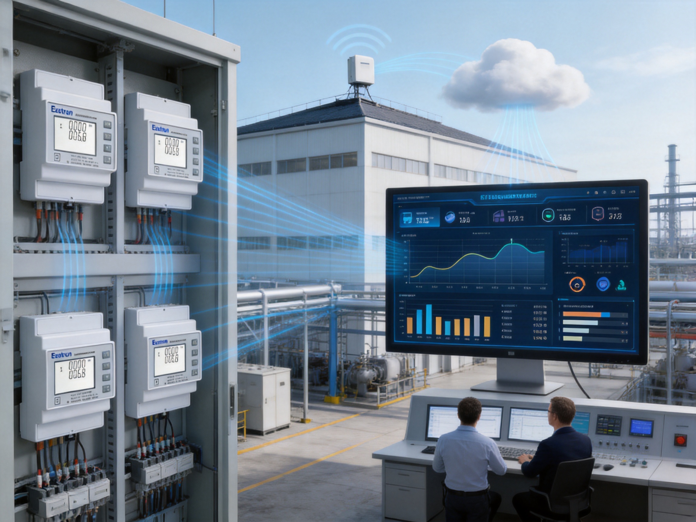
Correct installation is essential for obtaining reliable measurements. Before installation, the electrical system should be reviewed to determine the wiring configuration, nominal voltage, current range, CT secondary rating, communication requirements, and applicable safety procedures.
The meter accepts 1 A or 5 A CT secondary inputs. The selected CT secondary rating must correspond to the meter configuration. The CT primary ratio must also be entered correctly, because an incorrect ratio will produce an incorrect current and energy reading even if all other wiring is correct.
CT polarity and phase association are equally important. The current transformer for each phase should be installed in the correct orientation and connected to the corresponding voltage phase. Reversed polarity or mismatched phases can lead to inaccurate power-factor and power-direction calculations.
CT secondary circuits require careful handling. Installation personnel should follow the CT manufacturer’s safety instructions and applicable electrical standards. A CT secondary should not be treated casually, especially when the primary circuit is energized.
The meter supports three-phase systems with line-to-neutral and line-to-line voltage ranges suitable for common 230/400 V networks. The installer should confirm whether the site uses a three-phase four-wire or three-phase three-wire arrangement and select the correct wiring configuration.
Voltage connections should be protected and installed according to the requirements of the switchboard and the applicable local regulations. Before energization, technicians should verify phase sequence, neutral availability where required, terminal tightness, insulation, and protective devices.
For LoRaWAN operation, the correct regional frequency band must be selected. The meter should be commissioned within a network architecture that includes an appropriate gateway, network server, application platform, and data-security configuration. Radio coverage should be evaluated before final installation, particularly in metal enclosures, basement rooms, reinforced-concrete structures, and areas with significant electromagnetic obstruction.
Upload intervals should be selected according to the project’s monitoring objectives. Short intervals provide more detailed trends but may increase network traffic and application data volume. Longer intervals may be sufficient for monthly energy reporting and basic facility benchmarking.
For wired versions, communication addresses must be unique on the network. Baud rate, parity, stop bits, and protocol settings should match the host system. Even when a project uses LoRaWAN as the primary link, the availability of pulse outputs can provide an additional local data path for compatible equipment.
Password protection helps prevent unauthorized changes to CT ratios and other configuration values. Commissioning teams should document the original settings, secure the password, and maintain a record of any approved changes. A controlled configuration process reduces the possibility of unexplained measurement discrepancies.
The performance of an energy meter depends on more than its published specifications. Consistent production, engineering discipline, verification testing, and after-sales support are equally important. The manufacturer behind this product has developed a broad portfolio of electricity meters, power analyzers, current sensors, communication modules, and energy-management systems.
This product range indicates experience across several layers of energy measurement. A company that develops meters, sensors, communication modules, and management systems can evaluate product performance from both the field-device and system-integration perspectives. That broader understanding can help improve compatibility between measurement hardware and energy-management applications.
The company maintains development teams in China and the United Kingdom and continues to invest in new technologies for electricity metering. Cooperation with universities and technical institutions contributes to product development and the application of current engineering methods.
For a product such as the SDM630MCT-Lora, development expertise must cover metrology, embedded software, power electronics, communications, radio performance, enclosure design, and industrial manufacturing. LoRaWAN integration is not simply an additional connector; it requires coordination between measurement firmware, network behavior, regional frequency requirements, data formats, and field commissioning.
The manufacturer has established a professional laboratory capable of performing EMC, low-voltage, accuracy, and environmental tests according to IEC, EN, GB, and UL requirements. These test areas are important for energy meters used in real electrical installations.
Accuracy testing verifies that the meter remains within specified performance limits under defined voltage, current, power factor, and frequency conditions. EMC testing evaluates the equipment’s resistance to electromagnetic disturbances and the emissions it may produce. Low-voltage testing addresses electrical safety. Environmental tests help assess operation under temperature, humidity, and other physical conditions relevant to field use.
Internal laboratory capability can improve development efficiency because engineers can test design changes before formal external assessment. It also supports production monitoring and quality verification throughout the product life cycle.
The product information identifies active-energy performance under IEC 62053-21 and EN 50470-3:2022, as well as reactive-energy performance under IEC 62053-23. The meter is also described as ETL listed and assessed against the requirements of EU Directive 2014/32/EU, with a stated traceable assessment number.
Certification and listing requirements vary according to market and application. Nevertheless, experience with international standards gives system integrators greater confidence when evaluating equipment for projects in different regions. It also demonstrates that the manufacturer designs products with formal technical assessment in mind rather than relying only on internal claims.
The company holds patented technologies in software, embedded software, and hardware. This combination is relevant to a connected meter because product differentiation may involve not only the physical measurement circuit but also firmware functions, communication handling, configuration security, and data-management behavior.
Long-term experience in electricity products can also support production consistency. A mature manufacturer typically develops controlled processes for component sourcing, printed-circuit-board assembly, calibration, functional testing, firmware management, final inspection, and traceability. These processes help reduce variation between units and support stable field performance.
The company follows an ISO 9001 quality-management system and has production approved by SGS according to MID standards. Its products and services have been supplied to more than 50 countries across Europe, Asia-Pacific, America, the Middle East, and Africa.
International supply experience requires more than manufacturing capacity. It also involves documentation, export coordination, technical support, certification management, spare-parts planning, and communication with system integrators. These capabilities are valuable for customers deploying meters across multiple sites or national markets.
A connected meter is most useful when its information is converted into decisions. The SDM630MCT-Lora can act as a field measurement layer in a broader energy-management architecture. At the field level, the meter measures electrical parameters. At the communication level, LoRaWAN transfers data through the wireless network. At the application level, software presents trends, alarms, reports, and performance indicators.
Typical data workflows may include the following stages:
First, the meter measures voltage, current, power, energy, power factor, frequency, and related values from the connected electrical system.
Second, the meter prepares selected values for automatic transmission according to the configured upload interval.
Third, the LoRaWAN network carries the data through a compatible gateway and network service.
Fourth, the application platform stores the information and presents it through dashboards, reports, alarms, or automated analysis.
Finally, facility personnel use the information to adjust operating schedules, investigate abnormal loads, verify energy projects, allocate costs, or plan electrical-capacity improvements.
Data quality should be considered at every stage. The meter must be correctly installed, the CT ratio must be configured accurately, the communication network must be properly designed, and the application must interpret units and registers correctly. A reliable measurement project is therefore a combination of suitable hardware, disciplined commissioning, and well-designed software.
Energy-efficiency programs often fail to deliver their full value when improvements are not measured consistently. A connected meter provides a way to compare energy use before and after an intervention. For example, a facility may monitor a production line before installing a high-efficiency motor, then evaluate changes in active power and energy consumption after the upgrade.
Similarly, HVAC systems can be monitored across operating seasons. Lighting circuits can be compared between occupied and unoccupied periods. Compressed-air systems can be studied for excessive running time. Refrigeration equipment can be reviewed for changes in demand and power factor.
Because the meter collects both cumulative and instantaneous information, it can support different analysis methods. Cumulative energy values are useful for accounting and reporting. Instantaneous power values help identify demand peaks. Current and voltage values can reveal operating changes. Power factor and reactive power provide insight into electrical utilization.
Wireless connectivity can make it more practical to add measurement points gradually. A facility may begin with the main incoming supply and then expand to selected production lines, tenant areas, or utility systems. This modular approach can help organizations manage project cost and prioritize the loads with the greatest potential for improvement.
Reliable data requires regular attention even when the meter itself is designed for automatic operation. Maintenance teams should periodically review communication status, compare selected readings with reference instruments where appropriate, inspect CT connections, and verify that configuration records remain correct.
Offline detection can help identify communication problems, but it should be supported by a clear maintenance process. When an alert is generated, technicians can check the meter’s power supply, network coverage, gateway status, antenna placement, and application-server communication. A structured diagnostic process reduces the time required to restore service.
Automatic resume helps the meter return to communication after interruptions, but historical data handling should also be considered during system design. The data platform should define how missing values, delayed transmissions, duplicate messages, and time synchronization are handled. These software policies are important when energy information is used for reporting or billing analysis.
Periodic inspection should also include the mechanical condition of the panel, terminal tightness, signs of overheating, and the condition of external CTs. Electrical safety procedures must be followed during all inspection and maintenance work.
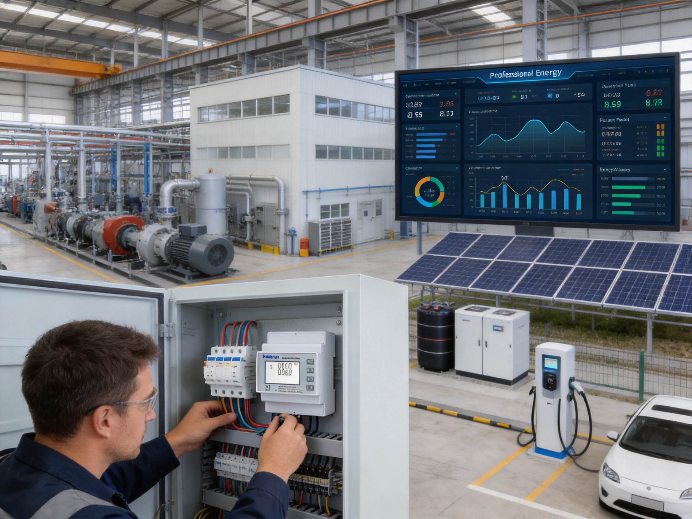
Before selecting the meter for a specific project, engineers should answer several practical questions. What type of three-phase wiring system is present? What are the nominal voltage and maximum current? Are 1 A or 5 A CTs already installed? How many measurement points are required? Is wireless communication permitted? What regional LoRaWAN band is needed? Does the project require formal metering certification? How often must data be uploaded?
The meter is a strong candidate when the project requires multifunction measurement, external CT flexibility, wireless long-range communication, and centralized data collection. It is especially suitable for retrofit applications where installing new communication cable would be difficult or costly.
For a small panel with an existing RS485 network, a wired version may be more economical or technically appropriate. For a utility-metering system built around M-Bus, the M-Bus configuration may be preferred. Product selection should therefore consider the entire system rather than focusing on the meter in isolation.
| Project requirement | Relevant product capability |
|---|---|
| Monitoring a three-phase feeder | 3P3W and 3P4W measurement support |
| Measuring high-current circuits | External CT inputs with configurable primary range |
| Collecting multiple electrical parameters | Voltage, current, power, energy, frequency, power factor, and demand-related measurements |
| Reducing communication cable installation | Integrated LoRaWAN communication |
| Operating in different regions | Support for multiple regional LoRa frequency bands |
| Detecting communication failures | Confirmation and offline-detection functions |
| Recovering after communication interruptions | Automatic-resume mode |
| Using a secondary data interface | Two pulse outputs on the LoRa configuration |
| Supporting formal technical evaluation | Stated IEC, EN, ETL, MID, and related assessment experience |
The meter is designed for three-phase AC systems and supports three-phase three-wire and three-phase four-wire arrangements. The published measurement description refers to RMS measurement including harmonics on three-phase systems.
No. The SDM630MCT-Lora uses external current transformers. It accepts 1 A or 5 A CT secondary inputs, and the CT primary setting can be configured from 1 A to 9999 A. The CT ratio must be selected and entered correctly during commissioning.
The rated voltage is 3 × 230/400 VAC. The stated voltage range is 100–277 V AC line-to-neutral and 100–480 V AC line-to-line.
It can measure voltage, current, frequency, power factor, active power, reactive power, apparent power, active energy, reactive energy, and demand-related information. The exact data available to an application depends on the product configuration and communication integration.
The product includes a LoRaWAN communication function. It supports regional frequency bands such as EU868, AS923, CN433, CN470, AU915, and US902, subject to the selected regional version and applicable regulations.
Yes. The product supports an automatic upload mode. Upload and download time intervals can be set or adjusted according to project requirements.
The meter supports confirmation, offline detection, and automatic-resume functions. These features can help identify communication interruptions and allow the device to return to normal operation after a temporary interruption. Overall data recovery also depends on the gateway, network server, application platform, and site power conditions.
The LoRa configuration is described as providing two pulse outputs together with LoRaWAN communication. Pulse outputs can be used by compatible external systems for energy-pulse collection or related integration purposes.
It can be suitable for retrofit applications, especially where current-transformer measurement and wireless communication can reduce the need for new high-current wiring or communication cable. Site conditions, radio coverage, panel space, CT compatibility, and local electrical rules must be evaluated before installation.
Active-energy performance is specified as Class 0.5 under IEC 62053-21 and Class C under EN 50470-3:2022. The appropriate certification requirements for a particular billing or regulated application should be confirmed before use.
Reactive-energy measurement is specified as Class 2 under IEC 62053-23.
Yes. The wider product family includes configurations with RS485 Modbus and M-Bus communication. This allows designers to select a communication method appropriate to the site infrastructure and integration requirements.
The CT primary value must match the installed transformer. The secondary input must also correspond to the 1 A or 5 A meter configuration. The installer should verify CT orientation, phase association, ratio, and wiring before energizing the system.
The meter provides RMS measurement including harmonics and a useful set of electrical values. However, applications requiring detailed analysis of transients, harmonics by order, flicker, events, or waveform capture may require a specialized power-quality analyzer in addition to the energy meter.
The manufacturer reports dedicated research and development teams, a professional laboratory for EMC, low-voltage, accuracy, and environmental testing, patented software and hardware technologies, ISO 9001 quality management, and experience with international standards and certification. These capabilities support product development, verification, production quality, and global technical service.
The SDM630MCT-Lora combines three-phase multifunction measurement with external CT flexibility and integrated LoRaWAN communication. It is designed for energy-monitoring projects that require more information than a basic kWh meter can provide and more installation flexibility than a fully wired architecture may allow.
Its measurement range includes voltage, current, active power, reactive power, apparent power, frequency, power factor, active energy, reactive energy, and demand-related information. Accuracy specifications, configurable CT ratios, support for 3P3W and 3P4W systems, and two pulse outputs extend its usefulness across commercial, industrial, infrastructure, and distributed-energy applications.
The communication features are especially valuable for IoT deployments. Automatic uploading, adjustable time intervals, confirmation, offline detection, broad regional frequency support, and automatic resume help the meter operate as part of a connected monitoring system. These functions can reduce manual data collection, simplify distributed installations, and improve awareness of communication status.
Compared with a basic energy meter, the product provides a richer view of electrical performance. Compared with a system assembled from separate meters, sensors, and communication modules, it can reduce integration complexity and offer a more unified field-device solution. Its relationship to a wider product family also allows system designers to consider Modbus, M-Bus, pulse, and dual-power-source options where appropriate.
The manufacturer’s research and development resources, laboratory capabilities, certification experience, quality-management system, and international service organization further support the product’s position in the energy-measurement market. For projects that require dependable electrical data, wireless connectivity, and scalable energy-management integration, this three-phase LoRaWAN multifunction meter provides a practical foundation.
IEC 62053-21, Electricity Metering Equipment: Particular Requirements for Static Meters for Active Energy.
IEC 62053-23, Electricity Metering Equipment: Particular Requirements for Static Meters for Reactive Energy.
EN 50470-3:2022, Electricity Metering Equipment: Particular Requirements for Static Meters for Active Energy.
EN 13757-3, Communication Systems for Meters and Remote Reading of Meters.
European Union Directive 2014/32/EU on Measuring Instruments.
ISO 9001, Quality Management Systems: Requirements.
LoRa Alliance, LoRaWAN Regional Parameters and Network Architecture Guidance.
SDM630MCT-Lora product technical information and electrical specifications supplied for this article.
Manufacturer information concerning electricity-meter development, testing laboratories, certification, quality management, and international technical support.
Your email address will not be published. Required fields are marked *

We develop and produce high performance electricity meters, power analyzers, current sensors, communication modules and management systems.
Address:NO. 52, Dongjin Road, Nanhu, Jiaxing, Zhejiang, China
Copyright @ Eastron Electronic Co., Ltd. All rights reserved
