

 English
 Español
 Deutsch
 中文简体


Product Consultation
Your email address will not be published. Required fields are marked *
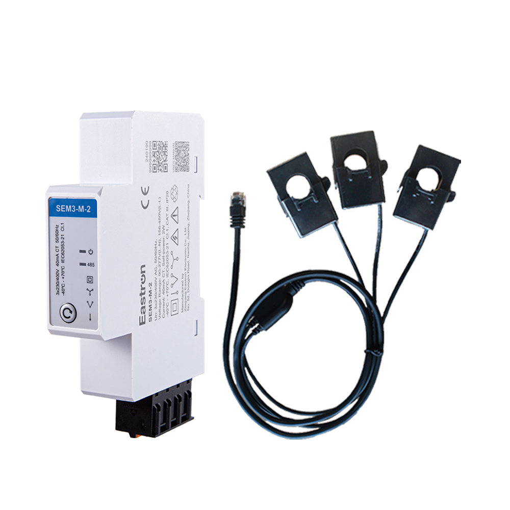
RS485 CT Connection Three Phase Din Rail Energy Meter for PV Metering
May 30,2025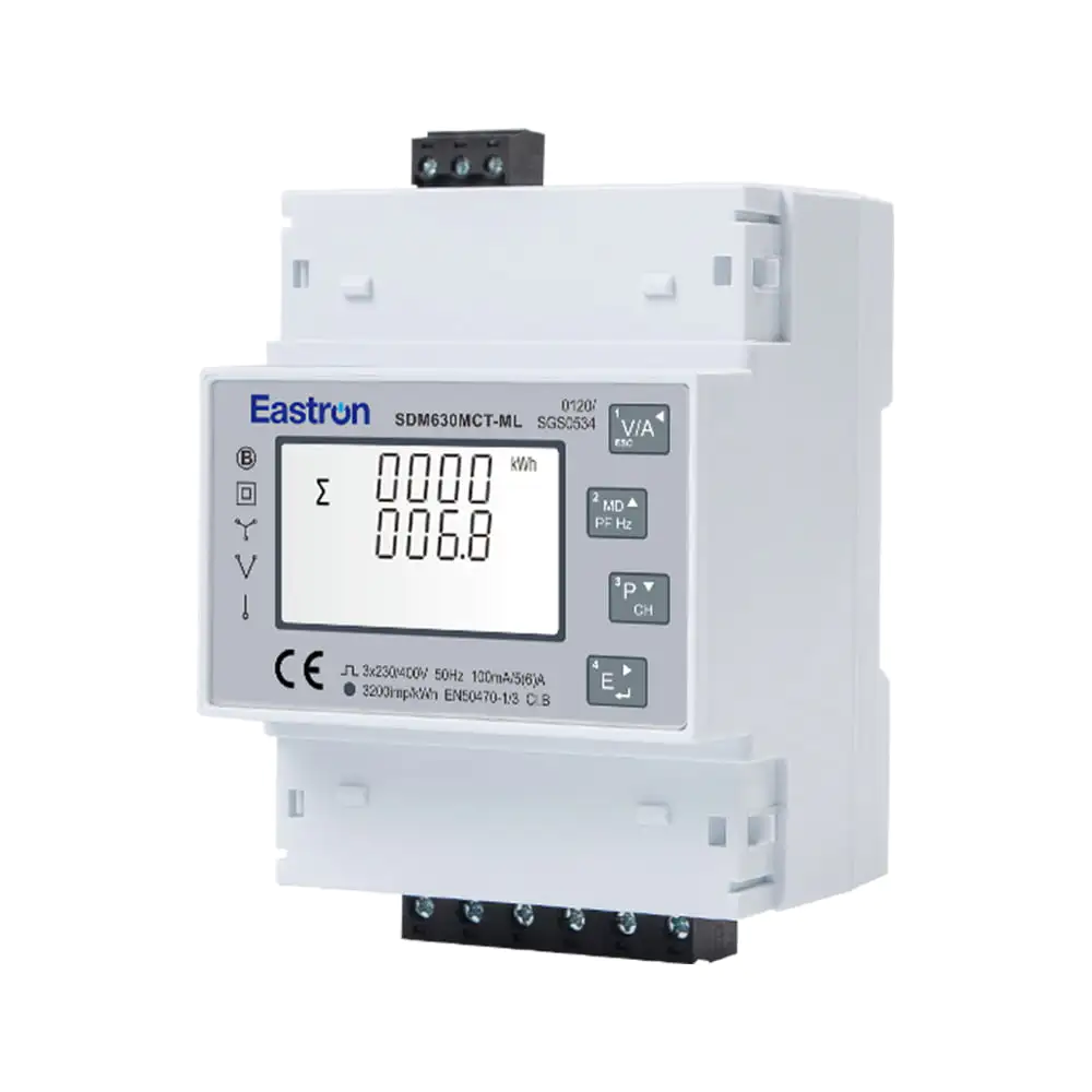
Quad Load Three Phase Multi-function RS485 Energy Meter for Data Center Metering
Aug 03,2022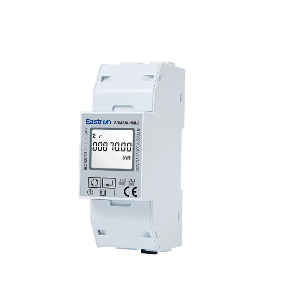
Dual RS485 Din Rail Single Phase Multi-function Solar PV/Zero Export Meter with 50mS Data Update for VPP Solution
Nov 24,2022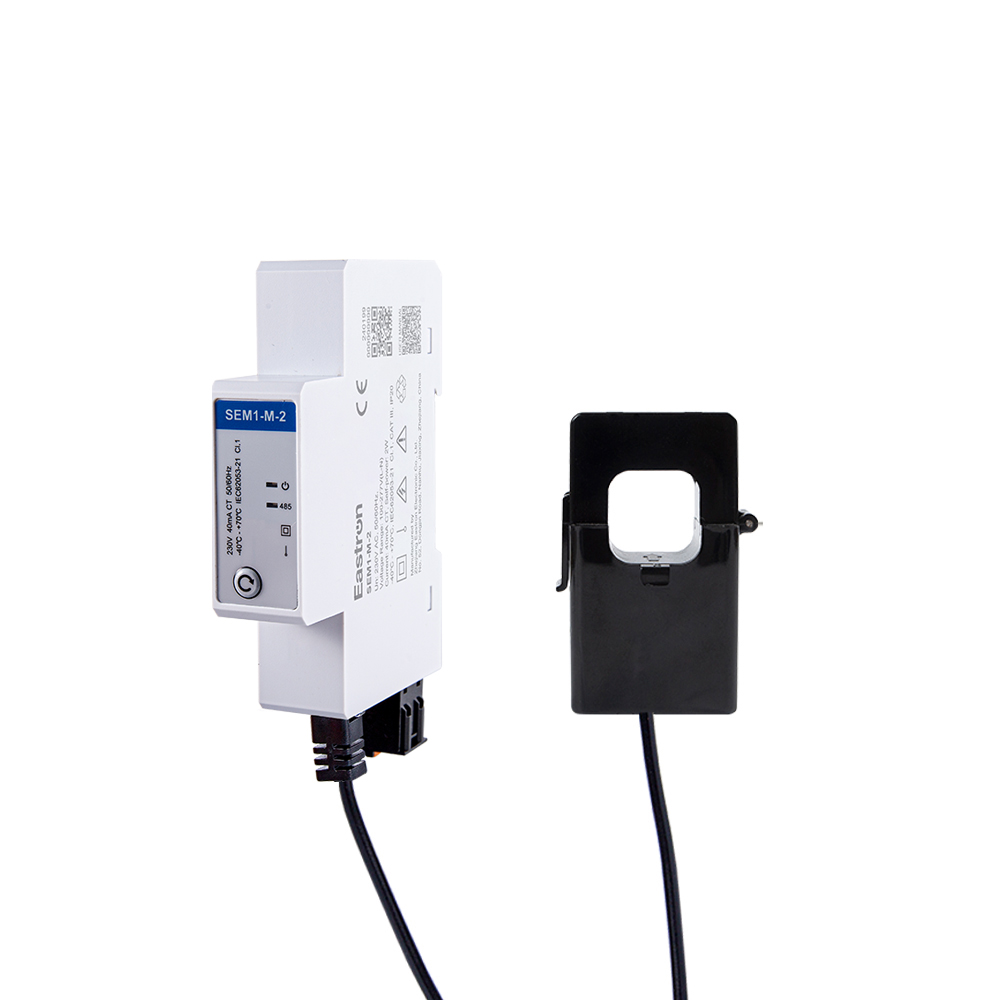
CT Type RS485 Modbus Single Phase Din Rail Energy Meter for PV Metering
May 30,2025
RS485 Modbus Din Rail Single Phase Electronic kWh Meter
Aug 11,2022
CT Type Three Phase Din Rail Wifi Energy Meter for PV Metering
May 30,2025Content
Modern electrical installations require more than a simple energy total. Facility managers, electrical engineers, system integrators, and equipment operators increasingly need to know how much energy is being consumed, when it is being consumed, which phase is carrying the load, whether the supply is within acceptable limits, and how equipment can be disconnected when a dangerous condition occurs. A meter that combines measurement, communication, alarm management, and remote switching can simplify this task while reducing the number of separate components in a control panel.
The SDM530C is a three-phase multifunction energy meter designed for four-wire alternating-current systems. It combines multi-parameter measurement, active and reactive energy monitoring, RS485 Modbus RTU communication, pulse output, and a built-in relay for remote power control. With support for applications up to 100 A, the meter is suitable for commercial distribution boards, industrial control panels, energy management systems, equipment monitoring, and remotely supervised electrical loads.
Its principal value is the integration of functions that are often distributed across several devices. A conventional energy meter may report consumption but provide no direct switching function. A separate relay or contactor may offer remote control but no information about the electrical conditions that caused the load to operate. A standalone power analyzer may deliver detailed measurements while requiring additional hardware for energy accounting and load disconnection. The SDM530C brings these functions together in one compact solution, allowing measurement data and control decisions to be connected through a common communication interface.
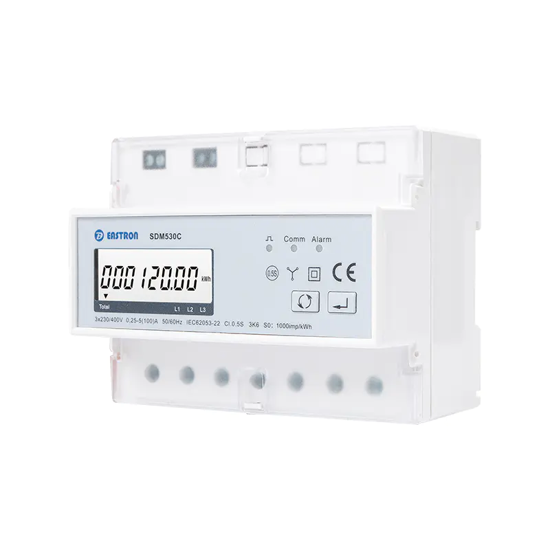
RS485 Remote Control Built-in Relay Three Phase Multi-function Energy Meter
The SDM530C is specified for a 3P4W, or three-phase, four-wire system. It measures RMS electrical parameters on a three-phase AC network with neutral. This configuration is widely used in commercial buildings, industrial facilities, workshops, retail premises, distributed equipment rooms, and other installations where individual phase conditions and total energy performance must be monitored.
The meter measures current, voltage, power, frequency, power factor, and energy. Energy readings include import and export energy, enabling the device to distinguish between energy consumed by a site and energy returned to the electrical network. This capability is especially useful in installations containing generators, renewable-energy systems, regenerative equipment, or bidirectional power flows.
In addition to measurement, the product provides a built-in relay for remote power control. Commands can be sent through RS485 communication using Modbus RTU. Depending on the application and configuration, the relay can be controlled collectively or on an individual-phase basis. The relay can also open automatically when configured alarm conditions occur, such as over-current or over-voltage events.
The SDM530C further supports pulse output for energy pulse emission. Pulse outputs are useful for connecting a meter to a pulse counter, building management system, data logger, programmable logic controller, or legacy energy-monitoring system. RS485 Modbus communication provides a more comprehensive method for reading measurement values, configuring parameters, checking alarms, and issuing control instructions.
| Function | Product Capability | Typical Application Value |
|---|---|---|
| Electrical system | Three-phase, four-wire AC measurement | Monitoring commercial and industrial low-voltage distribution systems |
| Maximum current | Up to 100 A | Direct monitoring of substantial individual loads and circuits |
| Measured parameters | Current, voltage, power, frequency, power factor, and energy | Electrical performance analysis and energy management |
| Energy types | Import and export energy, including active and reactive energy measurement | Bidirectional energy accounting and power-quality review |
| Relay | Built-in relay for remote and alarm-based power control | Remote disconnection, load management, and protective response |
| Communication | RS485 with Modbus RTU | Integration with automation, monitoring, and supervisory systems |
| Pulse output | Energy pulse emission | Connection to counters, controllers, and data-acquisition equipment |
| Tariff support | Multi-tariff operation available | Time-based energy analysis and cost allocation |
| Alarm capability | Up to 26 alarm values | Early warning and automated response to abnormal conditions |
Remote measurement is only one part of effective energy management. Once an abnormal condition or an operating decision has been identified, the system may need to take action. The built-in relay gives the meter a direct control role instead of limiting it to data collection.
An operator can use Modbus communication to turn a connected load on or off without visiting the electrical panel. This can be valuable in remote facilities, distributed equipment rooms, plant areas with restricted access, and locations where scheduled switching is required. For example, a system can disconnect a non-essential load during a demand-management event, isolate a circuit after an alarm, or restore a load after a maintenance sequence.
The relay also supports automatic action. When an alarm condition such as excessive current or excessive voltage is detected, the relay can be configured to open. This reduces the delay between measurement and response. In systems built with separate meters and relays, a programmable controller or external logic device is normally required to interpret the meter data and operate the switching device. The integrated approach can reduce wiring, simplify programming, and make the relationship between an alarm and a control response easier to manage.
Another important characteristic is the ability to control the relay of each phase together or separately. Coordinated control can disconnect a complete three-phase load, while individual-phase control can support more selective operating strategies. The appropriate control method depends on the connected equipment, local electrical regulations, system design, and the rating of the downstream switching arrangement.
The built-in relay should be evaluated as part of the complete installation. Engineers must confirm the relay contact rating, load type, inrush current, switching category, protection requirements, and whether an external contactor is necessary for the actual load. For high-inrush motors, heating equipment, capacitive loads, or circuits exceeding the direct switching capability, the meter relay may be used as a control signal for a suitably rated contactor rather than as the primary power-switching element.
Accurate measurement is essential when energy data is used for billing analysis, operational decisions, cost allocation, or equipment-performance evaluation. The SDM530C provides a stated active-energy accuracy of IEC 62053-22 Class 0.5s. This high-accuracy specification makes the meter suitable for demanding monitoring applications where energy readings must be more precise than those delivered by basic indication meters.
Reactive energy is specified according to IEC 62053-23 Class 2. Reactive energy information helps users understand the behavior of inductive and capacitive loads, identify power-factor issues, and assess the effect of compensation equipment. Although reactive energy does not represent the same type of consumption as active energy, it can influence network loading, equipment sizing, losses, and utility charges in some installations.
Power and current accuracy are specified as 0.5% of range maximum, while voltage accuracy is also specified as 0.5% of range maximum. Frequency accuracy is given as 0.2% of mid-frequency, and power-factor accuracy is specified as 1% of unity, or 0.01. These specifications provide a useful basis for comparing the meter with general-purpose monitoring products.
Accuracy should always be interpreted together with the installation conditions. Correct wiring, suitable conductor preparation, stable auxiliary supply conditions, appropriate current paths, and proper configuration of the nominal voltage and current are necessary to achieve the intended performance. The meter should be installed by qualified personnel in accordance with the wiring diagram, applicable electrical codes, and the requirements of the complete system.
The product data identifies a rated current of 5 A, a maximum current of 100 A, a minimum current of 0.25 A, and a starting current of 20 mA. These values should be reviewed against the exact ordering code and installation design before commissioning. In particular, the distinction between nominal or rated current and maximum measurable or permissible current is important. System designers should not assume that every installation can continuously operate at the maximum value without checking the relevant technical documentation and wiring requirements.
An energy total by itself cannot always explain why a facility is performing poorly. Two sites may consume the same number of kilowatt-hours while having very different electrical behaviors. One may operate stable, balanced loads, while the other may experience voltage variation, phase imbalance, poor power factor, high peak demand, or intermittent over-current conditions.
By measuring current on the three phases, the SDM530C helps users compare phase loading and identify unequal distribution. Phase imbalance can result in higher losses, additional stress on motors, overheating of conductors, and reduced system efficiency. Early detection gives maintenance teams the opportunity to redistribute single-phase loads or investigate equipment problems before they become serious.
Voltage measurement provides visibility into supply conditions. Under-voltage can affect motor starting, heating performance, control equipment, and sensitive electronic devices. Over-voltage can shorten equipment life and create safety concerns. When voltage information is combined with current and power readings, engineers can determine whether a problem originates from the supply, the connected load, or the interaction between both.
Power-factor measurement adds another layer of analysis. Low power factor can increase current for a given active-power demand and may contribute to higher network losses or additional utility charges. By recording power factor alongside active and reactive energy, the meter can support decisions about capacitor banks, variable-speed drives, motor operation, and load scheduling.
Frequency monitoring is relevant in installations supplied by generators, microgrids, or other sources where frequency stability may vary. A change in frequency can indicate a source-side issue, a generator-control problem, or a system operating outside its normal conditions. The meter’s multi-parameter approach makes it easier to correlate individual readings instead of assessing each measurement in isolation.
The inclusion of up to 26 alarm values gives the SDM530C a broader supervisory role than a basic energy counter. Alarm thresholds can be used to identify conditions that require attention or automatic action. Depending on the configured parameters and system strategy, alarms may be associated with current, voltage, power, frequency, power factor, energy, or other monitored values supported by the product configuration.
Alarm management is useful in several ways. A monitoring system can issue a notification when a reading exceeds a warning threshold. A higher-level control system can log the event, display it to an operator, and compare it with previous events. The built-in relay can provide an automatic response where immediate disconnection is required and the installation has been designed for that operating mode.
Multiple alarm values also enable staged protection and operational logic. A lower threshold may generate a warning, while a higher threshold may initiate a relay action. Separate thresholds can be used for different parameters or phases. This flexibility allows the meter to support preventive maintenance rather than merely reporting a fault after equipment has already been damaged.
Alarm settings should be selected carefully. Thresholds that are too sensitive may cause unnecessary switching or repeated nuisance alarms. Thresholds that are too high may fail to protect the equipment or may provide insufficient time for intervention. Commissioning should include verification of alarm direction, delay settings where available, relay behavior, reset behavior, and communication status.
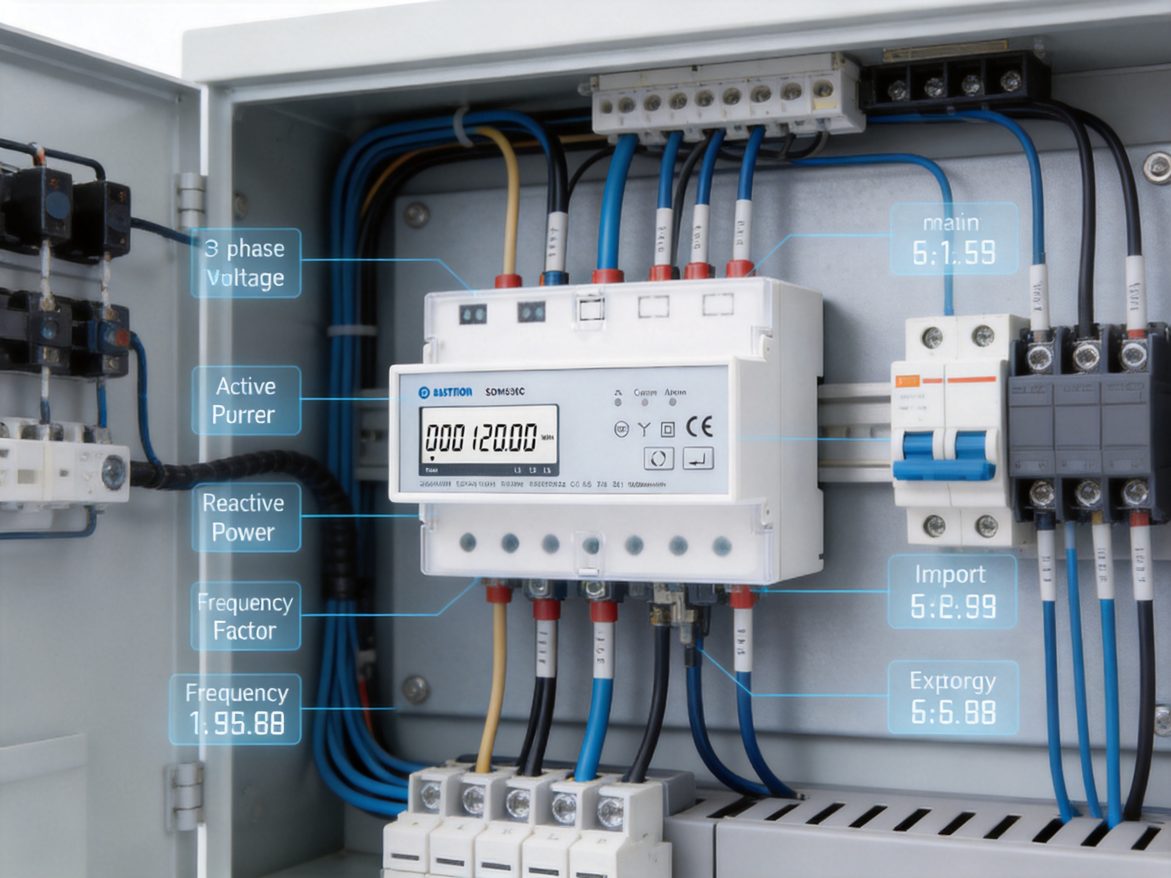
RS485 is widely used in industrial and building-automation environments because it supports reliable serial communication over long distances and allows multiple devices to share a network. The SDM530C uses RS485 Modbus communication for remote reading, setting, and control.
The stated communication address range is 1 to 247. This allows the meter to operate as one device within a larger multidrop network, provided that the overall network design follows the requirements of the controlling master and the RS485 physical layer. The specified maximum transmission distance is up to 1,000 metres under suitable conditions. Actual performance depends on cable type, baud rate, termination, grounding, electromagnetic interference, network topology, and the number of connected devices.
Supported baud rates range from 1,200 bps to 9,600 bps. Parity can be set to none, odd, or even, with none identified as the default. Stop-bit options are 1 or 2. These settings make the meter adaptable to many common PLC, gateway, SCADA, energy-management, and building-management systems.
Modbus communication provides access to information that may not be practical to obtain from a local display or pulse output alone. A supervisory system can periodically retrieve phase voltage, phase current, active power, reactive power, frequency, power factor, accumulated energy, alarm status, and relay status. It can also write configuration values or send relay commands where permitted by the control design.
For reliable communication, each device should have a unique address, and all network devices should use compatible serial settings. The RS485 cable should generally be arranged as a properly managed bus rather than a collection of long uncontrolled branches. Termination and biasing should be considered according to the network length and the requirements of the master. Communication wiring should be separated from high-noise power cables where practical.
One of the product’s competitive strengths is that RS485 is provided as an established industrial interface rather than a proprietary communication method. This makes integration easier for system designers who already operate Modbus-based networks. It can also reduce dependence on a specific software platform, because many industrial controllers, gateways, and monitoring applications support Modbus RTU as a standard field protocol.
The pulse output provides a simple method for transmitting energy information to external equipment. Each pulse represents a defined quantity of measured energy according to the meter’s configured pulse constant. A pulse counter or data logger can use this signal to collect consumption data without implementing a full serial communication protocol.
Pulse output can be useful when upgrading an existing installation. A facility may already have a building-management system or an older controller that accepts pulses but does not support Modbus. In that situation, the SDM530C can provide an energy-monitoring signal while RS485 remains available for a more advanced system or future expansion.
Multi-tariff operation supports time-based energy analysis. Users can distinguish energy associated with different tariff periods, operating schedules, or cost categories. This can help organizations understand when energy is being consumed and whether loads can be shifted to more economical periods. In commercial and industrial applications, this information can support production scheduling, demand management, and internal cost allocation.
Tariff functionality is particularly valuable when combined with remote control. For example, a supervisory system may identify a high-cost period and temporarily disconnect selected non-critical loads, provided that the operating conditions and safety requirements permit such action. The meter therefore contributes not only to measurement but also to an overall energy-management strategy.
A basic energy meter generally focuses on accumulating active energy. While this is sufficient for simple consumption recording, it provides limited insight into the conditions under which the energy was used. The SDM530C extends this capability with current, voltage, power, frequency, power factor, reactive energy, import energy, export energy, alarms, communication, pulse output, and relay control.
The additional information can reduce the need for multiple instruments. Instead of installing one energy meter, one power monitor, one communication module, and one separate control relay, a designer may be able to use the multifunction meter as the central measurement and command device. Fewer individual components can mean fewer connections, less panel space, simpler commissioning, and a more direct relationship between measured values and control actions.
Another advantage is the combination of local electrical intelligence and remote access. A simple meter may require a technician to visit the panel to read a value or change a setting. With RS485 Modbus communication, authorized users can access data from a central control room or software platform. This is especially beneficial when meters are installed throughout a large building, factory, campus, or geographically distributed equipment network.
The built-in relay also differentiates the product from meters that only observe. Remote control can support load shedding, scheduled switching, emergency response, maintenance isolation, and alarm-based disconnection. When properly engineered, these functions can improve operational efficiency and reduce the time required to respond to abnormal electrical conditions.
Separate devices can be highly capable, but they often require additional engineering. A meter must communicate with a controller, the controller must interpret the measurement, and the controller must operate a relay or contactor. Each interface introduces wiring, addressing, programming, and testing requirements.
An integrated product reduces the number of functional boundaries. The relay is part of the meter’s control architecture, and the meter already has access to the electrical readings used by alarm logic. This can simplify the design of a remote-control circuit, particularly in applications where the required action is directly related to a measured threshold.
Integration can also improve panel organization. A compact multifunction device may occupy less space than several separate modules. This can be important in retrofit projects where the existing distribution board has limited room. Reduced wiring can make fault tracing easier because the measurement and switching functions are associated with one clearly identified unit.
However, integration does not eliminate the need for correct system design. The meter should not replace protective devices such as circuit breakers, fuses, residual-current protection, or appropriately rated contactors. Its relay should be incorporated into a coordinated control and protection scheme. The advantage is not that it replaces every electrical component, but that it provides a practical combination of measurement and control within the monitoring layer.
Single-phase meters are suitable for individual circuits, but they can provide an incomplete picture in three-phase systems. A single-phase device cannot independently evaluate all phases, identify phase-specific over-current conditions, or compare phase loading across a complete 3P4W supply.
The SDM530C is designed for three-phase monitoring and can therefore provide a more comprehensive view of a facility’s electrical behavior. This is valuable for motor-driven equipment, mixed commercial loads, three-phase machinery, and distribution boards containing both three-phase and single-phase circuits.
Phase-by-phase data can reveal problems that total energy readings conceal. For example, the total current may appear acceptable while one phase is heavily loaded and the other two are lightly loaded. Similarly, one phase may experience a voltage issue that is not obvious from a total or average value. Three-phase measurement supports more informed balancing, maintenance, and capacity-planning decisions.
In commercial buildings, the SDM530C can monitor tenant circuits, lighting systems, HVAC equipment, refrigeration, server-room auxiliaries, elevators, pumps, and other significant loads. Energy readings can be allocated by department, floor, tenant, or operating function. The relay can provide remote control for selected non-critical circuits or support a building-management strategy.
In industrial plants, the meter can monitor production lines, machine groups, compressors, pumps, conveyors, heaters, and auxiliary services. Current, voltage, power factor, and frequency data can help maintenance teams recognize changes in operating behavior. Export-energy measurement can also be relevant where local generation or regenerative drives are present.
For workshops and small manufacturing sites, a multifunction meter can provide a cost-effective way to establish an energy-monitoring system without installing a large number of specialized instruments. Modbus communication allows the meter to connect to a central dashboard, while the pulse output can support simple local logging or integration with existing equipment.
In distributed facilities, the long-distance RS485 capability can support a network of meters installed across different panels. A gateway can collect the data and forward it to a supervisory platform. Centralized visibility helps users compare sites, identify unusual consumption, and plan maintenance based on measured conditions rather than assumptions.
The meter may also be used in energy-efficiency projects. Before an improvement is made, it can establish a baseline for energy consumption and electrical performance. After an upgrade, the same measurement points can help verify the result. This approach can be applied to motor replacement, lighting upgrades, HVAC optimization, production scheduling, or load-balancing projects.
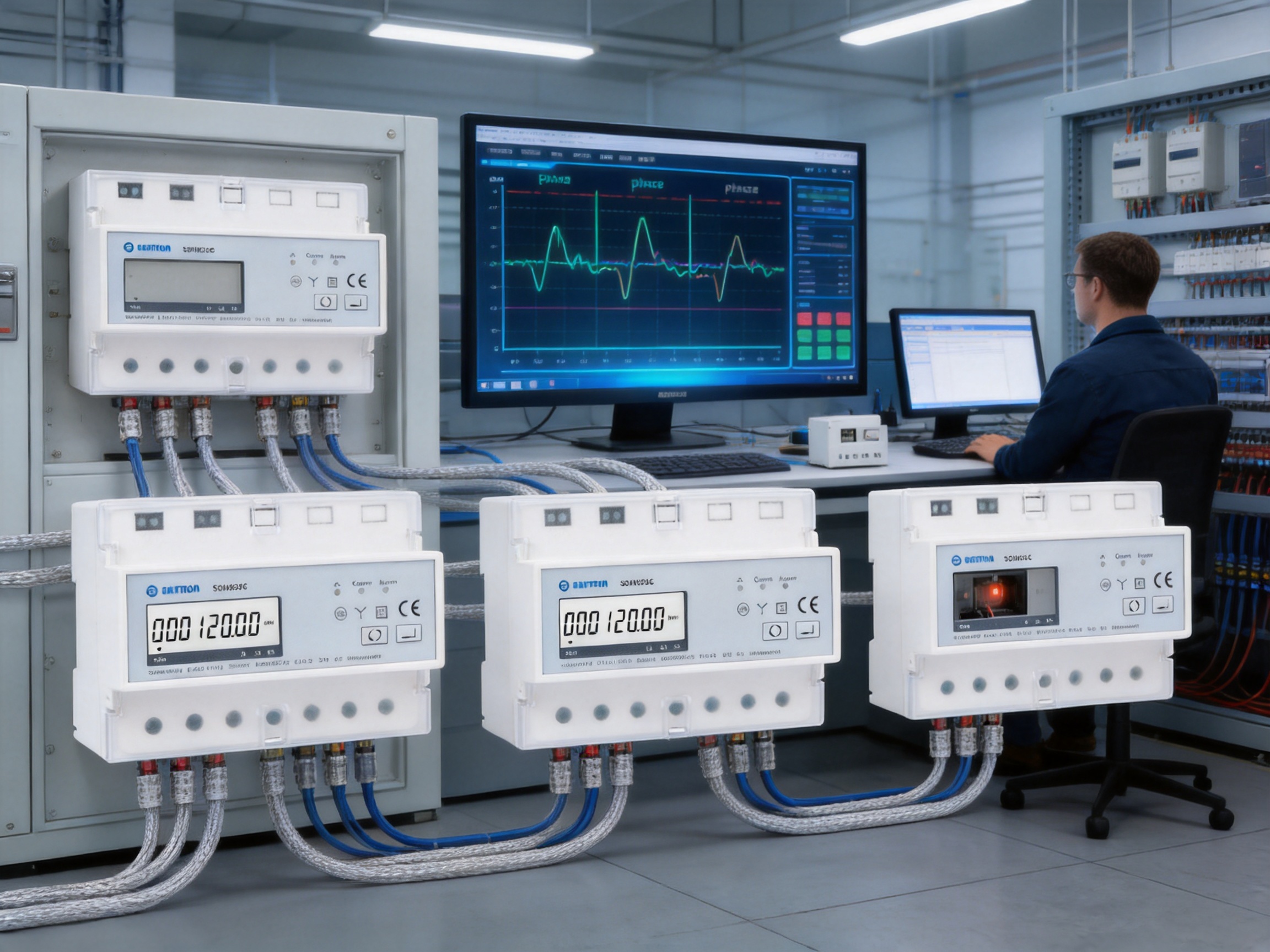
The product is manufactured by Eastron Electronic Co., Ltd., a company focused on electricity meters and energy-measurement solutions. Its product range includes electricity meters, power analyzers, current sensors, communication modules, and management systems. This product breadth is significant because it indicates experience across the measurement chain, from sensing and calculation to communication and system integration.
The company’s development activities are supported by engineering teams in China and the United Kingdom. Cooperation with universities and technical institutions contributes to research and development in electricity metering and related technologies. The company also reports patented technologies in software, embedded software, and hardware, demonstrating an emphasis on product development rather than simple assembly.
For a multifunction meter with remote-control capability, software and embedded engineering are especially important. Measurement accuracy depends on signal acquisition and calculation algorithms. Communication reliability depends on firmware design and protocol implementation. Alarm handling and relay behavior require coordinated embedded logic. The company’s experience in hardware and software development supports the integration of these functions into one product.
The company operates a professional laboratory capable of performing EMC, LVD, accuracy, and environmental tests according to IEC, EN, GB, and UL standards. Such testing is important for an electronic meter used inside electrically noisy commercial and industrial environments. Electromagnetic compatibility testing helps evaluate resistance to interference and unintended emissions. Low-voltage testing supports electrical safety evaluation. Accuracy testing verifies measurement performance, while environmental testing helps assess operation under specified conditions.
Testing throughout development and production is a major strength compared with low-cost products that may provide limited technical validation. A meter that communicates with industrial controllers and operates a relay must be evaluated not only for measurement accuracy but also for functional stability. Communication interruptions, incorrect alarm behavior, or unintended relay operation can create operational problems even when the energy calculation itself is accurate.
The company follows the ISO 9001 quality management system and reports production approval by SGS according to MID standards. These quality and conformity activities provide customers with additional confidence when selecting equipment for structured procurement, commercial projects, and professional installations. Specific certification status should always be confirmed for the exact product model and market before the meter is used in a regulated application.
A reliable energy meter begins with controlled component selection. Current-measurement circuits, voltage-sensing components, microcontrollers, memory devices, communication interfaces, relay components, terminals, and insulation materials must be selected for the required electrical and environmental conditions. Consistent component sourcing helps maintain product performance across production batches.
Electronic assembly must be managed carefully because measurement accuracy can be affected by solder quality, component placement, board contamination, thermal behavior, and signal-path interference. A professional production process typically includes printed-circuit-board assembly controls, visual inspection, solder-joint inspection, firmware programming, functional testing, and calibration or verification procedures.
Calibration and accuracy verification are especially important for meters. The product’s current and voltage channels must be checked across appropriate operating points, and calculated values such as power, energy, frequency, and power factor must be validated. Active and reactive energy performance should be assessed against the applicable technical requirements. This process helps identify errors that may not be visible during a simple power-on test.
Relay functionality requires additional testing. The relay must respond correctly to communication commands, alarm conditions, and reset or recovery procedures. The production process should verify contact behavior, insulation, switching response, and the relationship between relay status and reported status. Pulse output and RS485 communication should also be tested to confirm that external systems can receive accurate and stable signals.
Environmental and EMC testing provide another layer of confidence. Industrial panels can contain variable-speed drives, contactors, motors, switching power supplies, and long cable runs that generate electrical noise. A meter intended for such environments must be designed and tested for suitable immunity and emissions behavior. Environmental tests help assess operation across specified temperature, humidity, and other conditions.
The company’s laboratory capabilities in EMC, LVD, accuracy, and environmental testing allow these factors to be considered as part of the product-development and quality-assurance process. This is a meaningful advantage for customers seeking a meter from an experienced manufacturer rather than an unverified general-purpose supplier.
Successful integration begins with defining what the meter must measure and control. Engineers should identify the system voltage, number of phases, neutral arrangement, expected current range, load type, energy-flow direction, communication architecture, alarm requirements, and relay function. This information determines whether the SDM530C is suitable and how it should be configured.
The 3P4W connection must be wired correctly. Phase conductors and neutral must correspond to the meter terminals and the approved wiring diagram. Incorrect phase sequence, reversed current direction, missing neutral connections, or mismatched voltage inputs can produce incorrect readings or prevent correct operation. Installation should be completed by qualified electrical personnel.
Communication planning should include the Modbus address, baud rate, parity, stop bits, cable routing, network topology, and master-device polling strategy. A register map is required for software development and commissioning. The control system should also define how it handles communication loss, invalid readings, alarm status, relay status, and command confirmation.
For remote switching, the control philosophy should be documented in advance. The design should specify who may issue commands, what conditions permit switching, how manual override works, what happens after a power interruption, and how the system prevents unsafe or repeated operations. If the relay controls a contactor, the contactor coil circuit should include suitable protection and suppression where required.
Commissioning should include a comparison with a trusted reference instrument, verification of phase readings, confirmation of import and export energy direction, testing of pulse output, and a complete RS485 communication check. Alarm thresholds should be tested under controlled conditions, and relay actions should be observed and recorded. These steps help ensure that the meter’s capabilities are translated into dependable system performance.
Energy management is most effective when data is converted into action. The SDM530C can provide the data required to identify high-consumption equipment, compare operating periods, monitor power factor, and detect abnormal electrical conditions. Its communication and relay functions then allow the management system to respond.
For example, a facility may identify that a group of non-essential loads operates during a high-tariff period. If the process allows, those loads can be scheduled for a different time or disconnected temporarily through the relay-control system. Another facility may discover that one phase is consistently more heavily loaded than the others and use the data to rebalance the distribution board.
Export-energy measurement is useful for sites with photovoltaic generation, battery systems, or other distributed sources. By distinguishing energy flowing into and out of the installation, operators can assess self-consumption, monitor surplus generation, and understand the interaction between local generation and facility demand.
Reactive-energy data and power-factor readings can help identify opportunities to improve electrical efficiency. A low power factor may indicate underloaded motors, poorly selected compensation, or changing production conditions. Monitoring over time provides more useful information than a single inspection because it shows how the installation behaves under different loads.
Alarm records can support preventive maintenance. A gradual increase in current, repeated voltage alarms, or unusual frequency variation may indicate a developing issue. Maintenance teams can investigate before a failure interrupts production. This predictive approach can reduce unplanned downtime and help prioritize service work according to actual operating evidence.
The SDM530C is a monitoring and control instrument, not a substitute for the complete electrical protection system. Circuit breakers, fuses, isolators, residual-current protection, surge protection, and contactors must be selected according to the installation’s voltage, current, fault level, load characteristics, and applicable regulations.
The built-in relay must be used within its specified rating. Loads with high starting current or frequent switching may require an external switching device. Motors, transformers, compressors, heating systems, and capacitive loads can impose electrical stresses that differ significantly from those of resistive loads. A qualified engineer should determine the correct switching arrangement.
Remote control introduces additional operational responsibilities. Communication networks should be protected from unauthorized access, and control permissions should be defined. Software should not issue repetitive or conflicting relay commands. Where a remote command could affect safety-critical equipment, an independent safety circuit and local manual isolation should remain available.
Before maintenance, the relevant circuit should be isolated and verified de-energized according to established procedures. A communication command to open a relay should not be treated as the only means of electrical isolation unless the installation’s safety design explicitly permits it. Proper lockout and tagout procedures remain essential.
Verify that the installation is a three-phase, four-wire AC system and confirm the nominal voltage, current range, frequency, and neutral arrangement. Check whether the application requires direct connection, current transformers, or another measurement method. The available product information identifies a 230 V rated voltage and operation from 80% to 120% of nominal voltage.
List the required parameters, including current, voltage, active power, reactive power, frequency, power factor, import energy, export energy, and tariff data. Determine whether the project requires high-accuracy active-energy measurement or whether general monitoring performance is sufficient.
Decide whether the relay will control the phases together or separately. Identify the loads to be switched, the normal and emergency states, the required alarm thresholds, and whether an external contactor is needed. Document the response to communication failure and power restoration.
Assign a unique Modbus address and establish common baud-rate, parity, and stop-bit settings. Plan cable routes, termination, grounding, and the location of the RS485 master or gateway. Keep a complete record of device addresses and register assignments for future maintenance.
Check wiring, phase sequence, voltage readings, current direction, energy accumulation, pulse output, communication registers, alarm operation, and relay action. Compare critical readings with a calibrated reference instrument. Record the final settings so that future technicians can distinguish intentional configuration from a fault.
For facility managers, the SDM530C provides a practical combination of visibility and control. Managers can obtain information about energy use without relying entirely on manual readings and can coordinate selected load-control actions through a centralized system.
For electrical engineers, the product offers a broad measurement set, industrial communication, alarm values, and a relay in a single device. This supports more flexible panel and system designs while reducing the need to combine multiple basic instruments.
For system integrators, Modbus RTU and pulse output provide two integration paths. Modbus is appropriate for detailed, two-way communication, while pulse output is useful for simple energy accumulation or connection to existing systems. The choice can be made according to the capabilities of the host controller.
For maintenance teams, phase-level measurement and alarm information can help identify abnormal loads and prioritize inspections. Remote relay control can reduce unnecessary travel to panels, although safe isolation procedures must still be followed for physical maintenance.
For manufacturers and equipment builders, the meter can add energy-monitoring and remote-control capabilities to packaged machinery, distribution assemblies, and energy-management products. Its multifunction design can help standardize measurement across different equipment models.
The value of an energy meter should be measured over its operating life, not only by its purchase price. A device that provides reliable data, flexible communication, alarm support, and practical control can help reduce engineering time and improve the usefulness of an energy-management system.
Integrated functionality may reduce the number of separate components that must be stocked, wired, configured, and replaced. Common communication settings and centralized parameter access can simplify service across a group of installations. A manufacturer with a broader portfolio can also support related requirements, such as power analyzers, current sensors, gateways, and management systems.
Accurate measurement supports better financial decisions. Users can allocate energy costs more fairly, identify waste, verify efficiency projects, and recognize abnormal consumption. Remote control can support demand management and reduce unnecessary operation. Alarm functions can help prevent equipment damage or prolonged exposure to unfavorable electrical conditions.
The combination of product capability and manufacturer infrastructure is therefore important. The SDM530C is not merely a meter with a communication port. It is part of a broader approach to energy measurement in which hardware, firmware, testing, quality management, and technical support all contribute to practical performance.

The meter is designed for RMS measurement on a three-phase, four-wire AC system, commonly identified as 3P4W. It includes phase and neutral connections according to the applicable wiring arrangement.
The product information states a maximum current of 100 A. It also lists a 5 A rated current, a 0.25 A minimum current, and a 20 mA starting current. Engineers should confirm the exact model configuration and installation requirements before selecting the meter for continuous operation.
Yes. It is intended for multi-parameter, three-phase measurement and provides phase-related current and voltage information for electrical monitoring and analysis.
Yes. The product description identifies import and export energy measurement. This makes it suitable for installations where energy can flow in both directions, such as sites with local generation or regenerative equipment.
The meter uses RS485 Modbus RTU. The stated address range is 1 to 247, transmission distance is up to 1,000 metres under suitable conditions, baud rates range from 1,200 bps to 9,600 bps, and parity can be set to none, odd, or even.
Yes. RS485 Modbus RTU is commonly supported by PLCs, SCADA systems, gateways, building-management systems, and energy-management software. The host system must be configured using the product’s communication settings and register information.
The relay allows remote power control through Modbus communication. It can also open automatically in response to configured alarm conditions, such as over-current or over-voltage. The relay can be controlled collectively or separately by phase, depending on the application and configuration.
No universal assumption should be made. The relay must operate within its specified electrical rating and switching category. High-inrush, inductive, capacitive, motor, or high-power loads may require an external contactor or other suitably rated switching device.
The product information specifies up to 26 alarm values. The actual parameters, thresholds, delays, and response behavior should be confirmed in the relevant technical documentation and configured according to the system design.
Yes. Pulse output is provided for energy pulse emission. It can be connected to a pulse counter, controller, data logger, or another compatible energy-monitoring device.
Active energy is specified as IEC 62053-22 Class 0.5s. Reactive energy is specified as IEC 62053-23 Class 2. Other stated accuracies include 0.5% of range maximum for current and voltage, 0.5% of range maximum for power, 0.2% of mid-frequency for frequency, and 1% of unity for power factor.
Yes. Multi-tariff operation is identified as an available feature. It can help users analyze energy consumption across different time periods or tariff categories.
It combines active and reactive energy measurement with current, voltage, power, frequency, power factor, import and export energy, alarm management, RS485 communication, pulse output, and built-in relay control. A basic kWh meter normally provides a much narrower measurement and control scope.
The company reports laboratory capabilities for EMC, LVD, accuracy, and environmental testing according to IEC, EN, GB, and UL standards. These tests are relevant to the reliability, safety, measurement performance, and electrical compatibility of meters used in professional installations.
The meter is described as suitable for commercial and industrial applications. Final suitability depends on the installation environment, electrical ratings, temperature and humidity conditions, electromagnetic environment, enclosure design, and compliance requirements of the specific project.
No. The meter is a measurement and control device. It should be installed alongside appropriate circuit breakers, fuses, isolators, residual-current protection, surge protection, and other protective equipment required by the electrical design.
Confirm the system type, nominal voltage, current range, phase arrangement, communication requirements, relay application, pulse-output requirements, tariff needs, environmental conditions, and certification requirements. Also confirm the exact model suffix and technical documentation for the intended market.
The SDM530C offers a practical combination of three-phase measurement, energy accounting, alarm supervision, remote communication, pulse output, and built-in relay control. Its 3P4W design supports commercial and industrial distribution systems, while the multi-parameter measurement set helps users understand not only how much energy is being used but also how the electrical system is operating.
Its most notable advantage is the integration of monitoring and action. Through RS485 Modbus communication, users can read electrical data, adjust settings, review alarm conditions, and control the relay remotely. Automatic relay response to configured abnormal conditions can further improve system responsiveness when implemented within a properly designed protection and control scheme.
The manufacturer strengthens the product offering through experience in electricity meters, power analyzers, current sensors, communication modules, and management systems. Reported engineering resources, laboratory capabilities, quality-management practices, standards-based testing, and international market experience provide a solid foundation for professional applications.
For organizations seeking to improve energy visibility, simplify panel integration, support remote operation, and establish a foundation for energy-management improvements, this multifunction meter provides a versatile solution. Correct selection, installation, configuration, and commissioning remain essential, but the combination of measurement accuracy, communication flexibility, alarm capability, and relay control gives the product a strong position among integrated three-phase energy-monitoring devices.
IEC 62053-22, Electricity Metering Equipment — Particular Requirements — Static Meters for Active Energy, Class 0.5s and 1.
IEC 62053-23, Electricity Metering Equipment — Particular Requirements — Static Meters for Reactive Energy, Classes 2 and 3.
Modbus Organization, Modbus Application Protocol Specification.
Modbus Organization, Serial Line Protocol and Implementation Guide.
ISO 9001, Quality Management Systems — Requirements.
General principles of low-voltage electrical installation design, commissioning, inspection, and maintenance.
Manufacturer-provided SDM530C product specifications, electrical characteristics, communication parameters, and application information.
Your email address will not be published. Required fields are marked *

We develop and produce high performance electricity meters, power analyzers, current sensors, communication modules and management systems.
Address:NO. 52, Dongjin Road, Nanhu, Jiaxing, Zhejiang, China
Copyright @ Eastron Electronic Co., Ltd. All rights reserved
