

 English
 Español
 Deutsch
 中文简体


Product Consultation
Your email address will not be published. Required fields are marked *
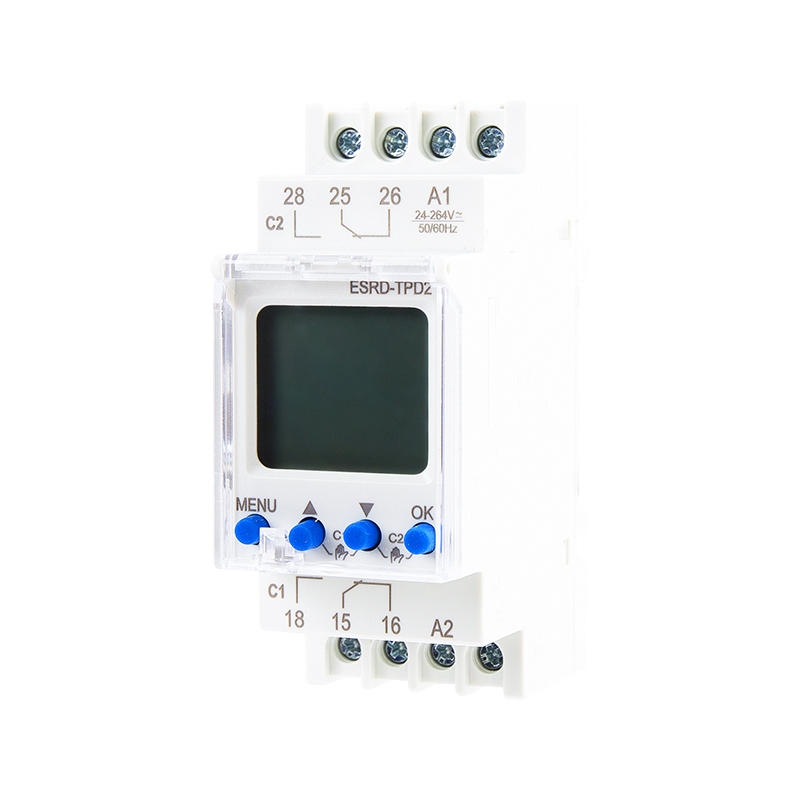
Pulse Program Double Channels Digital Weekly Time Switch
Aug 15,2022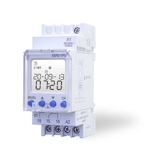
Pulse Program Single Channel Digital Weekly Time Switch
Aug 15,2022
Double Channels Din Rail DC Energy Meter 5-1000V DC RS485 Modbus
Aug 02,2022
Digital Input RS485 Modbus CT Operated Three Phase Multi-function Energy Meter
Nov 24,2022
Digital Input RS485 Modbus Din Rail Three Phase Multi-function Energy Meter
Nov 24,2022
Pulse Output Din Rail Three Phase Multi-function Energy Meter
Nov 24,2022Content
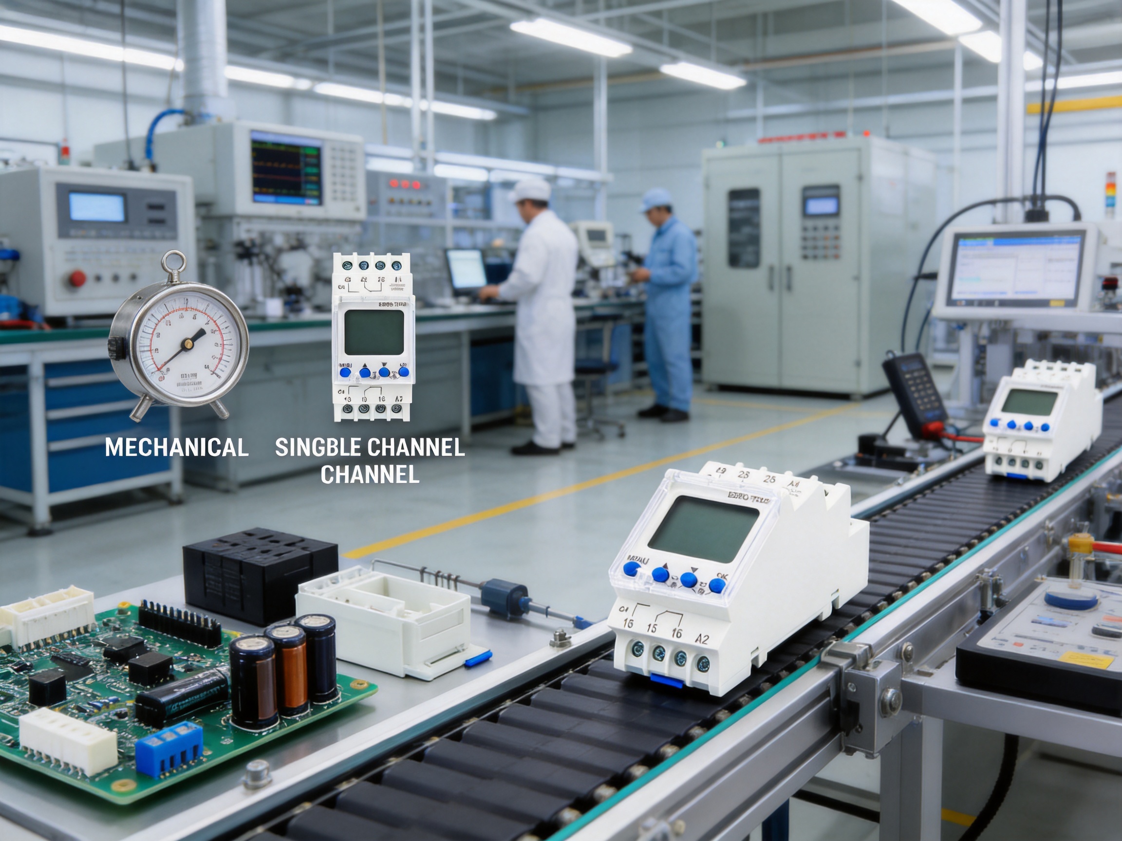
Modern electrical installations increasingly depend on precise, repeatable, and energy-conscious control of lighting, heating, ventilation, pumps, signage, access systems, and other scheduled loads. A reliable time switch provides a practical way to automate these functions without requiring a complex building-management system. The Pulse Program Double Channels Digital Weekly Time Switch, model ESRD-TPD2, is designed for this purpose. It combines weekly scheduling, pulse operation, holiday control, automatic seasonal time adjustment, a back-lighted LCD display, and two independently programmable channels in a compact DIN-rail device.
The unit is intended for control systems and automation applications in which electrical loads must operate according to a timetable defined by the user. Its internal lithium battery maintains the real-time clock and stored settings when the external supply is interrupted. With a rated supply range of 24–264 V AC/DC, the time switch can be integrated into a wide variety of control panels and distribution boards.
Compared with basic mechanical timers and simpler single-channel digital switches, this product offers greater programming flexibility, better visibility, longer data retention, and more adaptable operating modes. It is also supported by the engineering, testing, and manufacturing capabilities of Eastron Electronic Co., Ltd., a specialist producer of electricity products and energy measurement solutions. These capabilities include in-house laboratory testing, quality-system control, embedded-software development, hardware engineering, and production experience across international markets.
This article examines the product’s operating concept, key features, technical performance, installation value, application range, manufacturing strengths, and advantages over competing approaches. It also addresses practical selection questions so that system designers, electrical contractors, distributors, and end users can evaluate whether the ESRD-TPD2 is appropriate for a particular project.
Pulse Program Double Channels Digital Weekly Time Switch
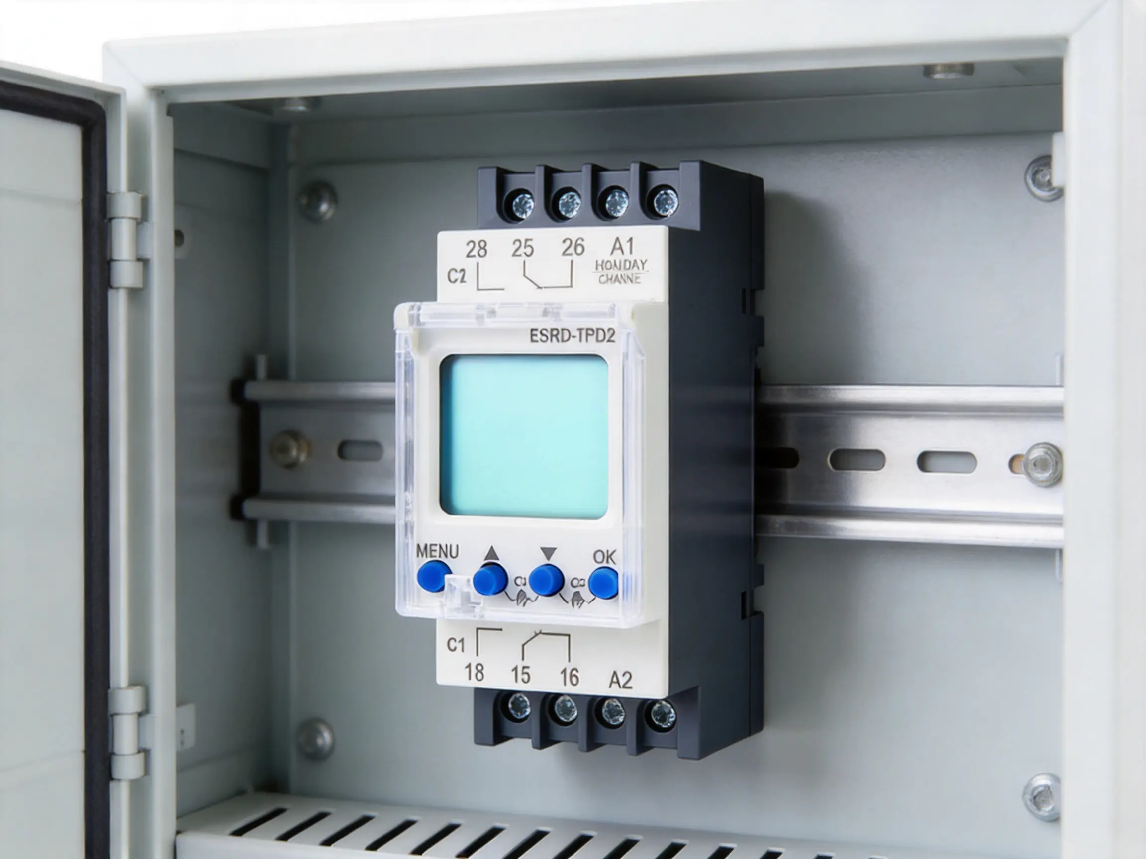
The ESRD-TPD2 is a programmable digital time switch for weekly and daily scheduling. It is installed on a standard DIN rail and occupies two modules, making it suitable for compact control cabinets and distribution boards. The front panel includes a back-lighted LCD display and four setting keys. A sealable front cover helps protect the control interface and can reduce the risk of accidental or unauthorized changes after commissioning.
The product is identified as a double-channel time switch. Each channel can be assigned an individual program, allowing two separate circuits or control functions to be managed from one device. For example, one channel may control exterior lighting while the second channel operates an advertising sign, ventilation fan, circulation pump, or security-related load. Independent channel programming reduces the need for multiple timers and can simplify both panel wiring and maintenance.
In addition to conventional on-and-off scheduling, the time switch supports pulse programs. A pulse program can generate a brief switching action at a specified time rather than maintaining an output for an extended period. This function is valuable for bell systems, door-control interfaces, signal relays, lighting triggers, dosing systems, and other applications that require a timed impulse instead of continuous energization.
The device supports manual, automatic, and holiday operating modes. Automatic mode follows the programmed schedule. Manual mode allows the operator to override the programmed state when immediate intervention is required. Holiday mode enables temporary changes to normal operation during a defined absence period, helping avoid unnecessary switching and energy use while maintaining a predictable return to the standard schedule.
The time switch provides a broad range of functions for a product in its compact class. These include a weekly program, daily programming capability, pulse operation, automatic summer/winter time change, manual override, holiday mode, automatic transfer of weekdays, and a battery-backed real-time clock. The combination is particularly useful where operating schedules vary by day or where equipment must respond differently on weekdays, weekends, and holidays.
The internal lithium battery provides a stated power reserve of up to ten years. This reserve protects the clock and stored settings when the main electrical supply is unavailable. As a result, a temporary outage does not necessarily require the installer or operator to re-enter the schedule. Long-term power reserve also reduces routine service requirements and improves confidence in unattended installations.
The display is back-lighted to improve readability in control rooms, plant areas, electrical cabinets, and other locations where ambient lighting may be limited. The four-key interface is intended to make programming accessible without a separate programming tool. Once the time switch has been configured, the sealable cover can help preserve the settings and provide a visible indication of controlled access.
A digital weekly time switch stores a set of instructions defining when an output should change state. These instructions generally contain a day or group of days, a time, an action, and, where relevant, a pulse duration. The internal clock compares the current time with the stored schedule and activates the associated relay contact at the programmed moment.
Weekly scheduling allows a user to create different routines for different days. A lighting circuit may switch on before business opens from Monday through Friday, operate for shorter periods on Saturday, and remain off on Sunday. A heating or ventilation system may use an entirely different timetable. Because each channel can be assigned an individual program, the two outputs do not have to follow the same operating pattern.
Daily programming is useful when a schedule must be repeated across selected days. The user can apply a switching event to a single day, a group of weekdays, weekends, or another required combination. Automatic transfer of weekdays supports faster setup and helps reduce repetitive data entry during commissioning.
Pulse programming changes the nature of the output action. Instead of switching a circuit on at one time and off at a later time, the time switch can provide a brief output pulse. The exact use depends on the connected control circuit and the programmed parameters. When the controlled load requires a longer or higher-current operation, the time switch can be used to drive an external contactor or relay rather than switching the load directly.
Seasonal time adjustment is another important scheduling feature. The automatic summer/winter time switchover can prevent a complete schedule from becoming offset when local time changes. Where a site does not use seasonal adjustment, the function can be switched off. This flexibility is helpful for international installations and for applications that require a fixed time reference throughout the year.
The two-channel design is one of the product’s clearest advantages over a conventional single-channel timer. A single device can coordinate two related but different systems. For instance, a retail facility may use Channel 1 for interior lighting and Channel 2 for exterior signage. A residential or commercial building may use one channel for heating and another for ventilation. An industrial panel may use one output for a pump schedule and the other for an alarm or auxiliary control function.
Independent programming also supports staggered starting. Large installations often benefit from starting loads at different times rather than energizing every load simultaneously. Staggered schedules can reduce peak demand, limit inrush-related disturbances, and provide a smoother startup sequence. The time switch should still be applied within the ratings of its relay contacts and the requirements of the connected equipment.
Although the product data identifies the device as a double-channel model, one technical-data entry lists the number of channels as one. This apparent inconsistency should be resolved by confirming the exact ordering configuration, terminal arrangement, and current datasheet with the supplier before purchase. The product title, description, and feature list consistently identify a double-channel version, while the detailed table may reflect a related configuration or a catalog-entry error. Careful verification is especially important when a project depends on two independent relay outputs.
The rated supply range is AC/DC 24–264 V. This broad range allows the device to be supplied from common control voltages and many distribution-system sources. It can therefore be used in panels where the available auxiliary voltage differs from one project to another. The rated frequency is 50/60 Hz, and the stated power consumption is approximately 1 W.
The switching contact rating is specified as 16 A at 250 V AC, with a stated AC-1 switching capacity of 4000 VA and a DC switching capacity of 384 W. These values should be interpreted in the context of the load category, inrush current, power factor, motor characteristics, lamp-driver behavior, and local installation standards. Resistive loads are generally easier to switch than motors, compressors, transformers, or electronic power supplies with high inrush currents.
For demanding loads, the time switch can operate an intermediate contactor. This approach protects the timer contacts from unsuitable electrical stress and permits the control of higher-power circuits through an appropriately selected switching device. The installer should consider contactor coil suppression, minimum switching current, short-circuit protection, conductor sizing, and separation between control and power wiring.
The rated insulation voltage is 250 V, and the stated protection degree is IP20. IP20 indicates protection against solid objects of specified size but not protection against water. The time switch should therefore be installed inside a suitable enclosure or distribution board where it is protected from moisture, condensation, dust beyond the specified level, and mechanical damage.
The specified pollution degree is 3. This classification is consistent with many industrial, commercial, and distribution-board environments where nonconductive pollution may occur and temporary conductivity can result from condensation. Installation conditions should remain within the intended environmental category, and the enclosure should provide the necessary protection for the complete assembly.
The operating temperature range is stated as -20°C to 55°C, while the storage range is -30°C to 70°C. These limits support use in many indoor electrical rooms, control panels, commercial buildings, and sheltered industrial locations. The installer should account for heat generated by adjacent equipment, direct sunlight, enclosure ventilation, and cold-start conditions.
The supported wire size is listed as 1 mm² to 4 mm². Actual conductor selection must follow the load current, protective-device rating, terminal requirements, national electrical codes, and the wiring method. Terminals should be tightened to the recommended torque, and conductors should be properly stripped and secured to prevent loose connections or overheating.
| Specification | Stated value | Practical significance |
|---|---|---|
| Supply voltage | 24–264 V AC/DC | Suitable for a broad range of control and auxiliary supplies |
| Rated frequency | 50/60 Hz | Compatible with common power-system frequencies |
| Power consumption | Approximately 1 W | Low operating demand for continuous installation |
| Channels | Double-channel product description | Two individually programmable outputs; verify final configuration |
| Programs | Up to 90 in technical data; product content also states 100 | Confirm the current model revision and software capacity |
| Program types | Weekly, daily, pulse | Supports recurring schedules and timed impulses |
| Operating modes | Manual, automatic, holiday | Provides normal scheduling and temporary override options |
| Power reserve | Up to 10 years | Protects clock and settings during supply interruption |
| Relay rating | 16 A/250 V AC | Suitable for appropriately rated loads within the application category |
| AC-1 capacity | 4000 VA | Useful reference for suitable resistive or low-inrush loads |
| DC capacity | 384 W | Requires careful review of DC voltage, current, and switching conditions |
| Mounting | Two-module DIN rail | Efficient use of panel space |
| Protection degree | IP20 | Requires installation in a suitable protective enclosure |
| Operating temperature | -20°C to 55°C | Supports many indoor and sheltered panel environments |
| Standards | IEC/EN 60730-1 and IEC/EN 60730-2-7 | Relevant safety and automatic-control reference standards |
The supplied information also contains two different program-count references: the product content mentions 100 programs, while the technical data lists 90 programs. This should be treated as a configuration or documentation point requiring confirmation. In either case, the product is positioned as a high-capacity programmable timer rather than a basic device with only a few daily events.
Mechanical timers are familiar, inexpensive, and simple, but they often provide limited resolution and restricted scheduling options. Their rotating dials or small mechanical segments may not support pulse operation, holiday mode, independent channels, or automatic seasonal adjustment. Mechanical components can also be affected by wear, vibration, dust, and changes in mechanical accuracy over time.
The ESRD-TPD2 replaces the mechanical programming interface with a digital system that can store multiple events and display the operating state clearly. Digital programming is more suitable for sites where schedules change by weekday or where operators need to make temporary adjustments without physically moving a dial. The real-time clock and battery reserve also maintain the programmed logic during an outage.
Many entry-level digital timers control only one output. A second timer may be needed for a separate load, increasing panel occupancy, wiring complexity, installation time, and maintenance effort. A double-channel product can coordinate two functions in one enclosure location while allowing each channel to follow its own program.
This does not mean that two independent timers are never appropriate. Separate devices may be preferable when circuits require different supply arrangements, different physical locations, or independent service isolation. However, when two scheduled functions are located in the same panel, the double-channel architecture can provide a more compact and integrated solution.
Without a power reserve, a timer may lose its clock or require reprogramming after a prolonged outage. That can lead to incorrect lighting schedules, disrupted process operations, missed ventilation periods, or unnecessary service visits. The stated ten-year lithium-battery reserve helps maintain the clock and stored parameters, improving resilience and reducing the administrative burden after power interruptions.
Automatic summer/winter time adjustment is particularly valuable for commercial buildings, public facilities, and distributed installations. It avoids the need to manually revise every scheduled event when local time changes. At the same time, the ability to disable automatic changes is important for applications that use a fixed operating reference or locations where seasonal time changes do not apply.
The back-lighted LCD display makes the current time, programmed events, operating mode, and channel status easier to inspect than an unmarked mechanical dial. The sealable front cover helps prevent accidental changes and supports controlled commissioning. In shared facilities, these features can improve accountability because authorized personnel can set or review the schedule while reducing casual interference.
Offices often need different schedules for interior lighting, exterior lighting, reception areas, ventilation, and signage. Weekday and weekend operation may differ substantially, and holiday periods may require a temporary shutdown. The time switch can control suitable circuits according to occupancy patterns, helping reduce operating hours and avoid equipment being left on unnecessarily.
A common arrangement is to use one channel for general-area lighting and another for exterior or security lighting. The two channels can operate at different times, and manual control can be used during special events, maintenance, or extended business hours.
Retail premises frequently operate signs, window lighting, display lighting, and auxiliary equipment according to opening hours and local conditions. Pulse programming can be useful for trigger-based advertising or control interfaces, while weekly scheduling supports different routines for shopping days and weekends. Holiday mode can suspend or modify normal operation during store closures.
Apartment blocks, housing developments, and residential facilities may use time-controlled lighting in common areas, car parks, entrance halls, staircases, and outdoor spaces. A pulse output can also be connected to a suitable control relay for door, gate, or access-related functions. Because the timer is installed in a panel, it can centralize scheduling for shared services while keeping the front interface accessible to authorized maintenance personnel.
Heating and ventilation equipment often benefits from scheduled operation based on occupancy. The time switch can provide a straightforward control signal for an appropriate contactor, relay, or control input. Separate channels may be used to coordinate heating and ventilation, or to operate a primary system and an auxiliary system with staggered start and stop times.
Designers must distinguish between scheduling and safety control. A time switch is not a replacement for thermostats, overload protection, emergency stops, frost protection, airflow monitoring, or other safeguards required by the equipment. It should function as one element in a properly engineered control circuit.
Industrial workshops, storage facilities, greenhouses, barns, and utility rooms may require scheduled lighting, ventilation, pumps, heating, or auxiliary machinery. The wide supply range and DIN-rail mounting make the device suitable for integration into many control panels. Its temperature range supports numerous indoor and sheltered environments, provided that the complete installation remains within the specified conditions.
Pulse operation can be used for controlled starting signals, valve actuators, dosing interfaces, and other equipment that accepts a short relay command. For inductive or high-inrush loads, an intermediate switching device should be selected and installed in accordance with the equipment manufacturer’s requirements.
Public buildings, small utility installations, parking areas, community centers, and service facilities often need predictable schedules without the cost or complexity of a networked automation system. The ESRD-TPD2 can provide local, self-contained scheduling for lighting and auxiliary services. Its battery-backed clock is useful in locations where power interruptions may occur and service access is not immediate.
Installation should be performed by a qualified electrical professional. Before mounting the device, the installer should verify the supply voltage, circuit design, load type, protective devices, required number of channels, and applicable regulations. The wiring diagram supplied with the actual product should be used because terminal assignments and contact arrangements must not be inferred solely from the product name.
The two-module DIN-rail format allows the time switch to be mounted alongside circuit breakers, contactors, relays, terminal blocks, and other control components. Adequate spacing and logical arrangement can improve serviceability. Heat-producing equipment should not be placed so close to the time switch that the ambient temperature exceeds the specified operating range.
The supply terminals are identified as A1–A2 in the technical information. Output terminals and contact arrangements should be checked against the current wiring diagram before connection. The control circuit should include appropriate overcurrent protection. Where the output operates a contactor, the coil voltage must match the control design, and suppression may be necessary to reduce electrical interference.
After installation, the technician should set the date and time, select the summer/winter time function, configure each channel, and verify the operating mode. Each programmed event should be checked against the intended day and time. Pulse duration and output response should be tested with the connected control circuit in a safe condition.
Manual control is useful during commissioning because it allows the installer to verify that each relay output, contactor, indicator, and connected load responds correctly. Once testing is complete, the device can be returned to automatic mode. The front cover may then be sealed if the application requires restricted access.
The published 16 A/250 V AC rating should not be treated as a universal rating for every load. Motors, pumps, compressors, fluorescent lighting, LED drivers, transformers, and capacitive power supplies may produce inrush currents that exceed the steady-state current. Contact welding, accelerated wear, or nuisance tripping can result if the switching device is incorrectly sized.
For such loads, a properly selected contactor or interface relay should carry the power current, while the time switch provides the scheduling signal. The interface device should be selected according to voltage, current, utilization category, inrush behavior, switching frequency, and mechanical life. The published mechanical life of the time switch relay is 106 operations under applicable test conditions, but the actual service life depends on the electrical load and switching environment.
Because the product is rated IP20, it should not be installed in a location exposed to water, oil spray, condensation, or uncontrolled dust. An appropriate enclosure should be used for industrial or outdoor applications. Where temperature varies significantly, designers should consider condensation prevention and enclosure ventilation.
The stated pollution degree of 3 provides a useful reference for installation planning, but it does not remove the need for a suitable cabinet. Cable entry points should be arranged to prevent moisture ingress, and unused openings should be sealed. Clear labeling of supply, output, and control conductors makes future maintenance safer and faster.
The four-key interface is designed for direct programming at the device. A typical setup sequence includes entering the clock-setting menu, selecting the time and date, choosing seasonal-time behavior, selecting a channel, defining the event type, and assigning days and times. The operator should consult the model-specific manual for the exact key sequence because menu labels and programming steps may vary by revision.
Automatic mode is the normal operating state for a scheduled installation. In this mode, the time switch follows stored events and changes the output according to the internal clock. Manual mode permits temporary or maintained output control, depending on the selected manual function. After manual intervention, the operator should confirm whether the device has returned to automatic operation or remains overridden.
Holiday mode is useful when a facility will operate differently for a planned period. Instead of deleting normal weekday and weekend programs, the user can activate a temporary holiday behavior. This reduces the risk of losing the regular schedule and makes it easier to restore ordinary operation after the holiday period.
The LCD display provides a local indication of the clock and programmed state. The backlight supports inspection in dim environments, although the panel should still be positioned where the operator can safely access it. A sealable cover can be used after setup to limit unauthorized changes while preserving visual access to the display, subject to the enclosure design.
The product is manufactured by Eastron Electronic Co., Ltd., a company focused on electricity products and energy measurement solutions. Its portfolio includes electricity meters, power analyzers, current sensors, communication modules, management systems, and related control products. This product breadth is relevant to the time switch because it reflects experience in electrical measurement, signal handling, embedded systems, and control-panel integration.
Advanced manufacturing is not limited to the final assembly of a plastic housing and circuit board. A dependable digital time switch requires coordinated design of the power supply, relay output stage, real-time clock, lithium-battery backup, display, keypad, enclosure, terminals, insulation system, and firmware. Each subsystem must operate reliably across the declared voltage and temperature ranges.
The company’s development teams in China and the United Kingdom support hardware, software, and embedded-software development. This combination is valuable for products that require both electrical engineering and user-oriented firmware. A time switch must interpret key inputs, store schedules, maintain clock accuracy, manage seasonal changes, handle power interruptions, and present understandable information on a small display.
Cooperation with universities and research institutions can further strengthen product development by providing access to specialist knowledge and testing resources. Patented technologies in software, embedded software, and hardware demonstrate an emphasis on proprietary engineering rather than dependence solely on off-the-shelf functionality.
Eastron reports that it operates a professional laboratory capable of EMC, low-voltage, accuracy, and environmental testing according to IEC, EN, GB, and UL-related requirements. For a programmable electrical control device, such testing is important. Electromagnetic compatibility testing helps evaluate whether the product can operate correctly in the presence of electrical disturbances and whether it creates unacceptable interference.
Low-voltage and insulation testing support electrical safety evaluation. Environmental testing helps assess operation under temperature and other physical conditions. Although a laboratory capability does not replace project-specific verification or certification review, it indicates that product development and production can be supported by controlled technical testing rather than visual inspection alone.
The company follows an ISO 9001 quality-management system. A structured quality system can support document control, supplier evaluation, process monitoring, corrective action, traceability, and continual improvement. These disciplines are important when producing electronic control devices in volume because small variations in components, soldering, calibration, relay assembly, or programming can affect field reliability.
Production approval by SGS according to MID standards, as stated in the company information, reflects experience with demanding verification environments associated with metering products. The ESRD-TPD2 is a time-control device rather than an energy meter, so the relevant compliance requirements should be confirmed for the specific model. Nevertheless, experience with regulated electrical products can contribute to disciplined design and manufacturing practices.
The company states that its products and services have been supplied to more than 50 countries across Europe, Asia-Pacific, America, the Middle East, and Africa. International supply experience requires attention to regional electrical systems, documentation, language needs, installation practices, environmental conditions, and conformity expectations. It can also improve the manufacturer’s ability to support distributors, system integrators, and technical users in different markets.
For buyers, this background may reduce the risk associated with selecting an unfamiliar supplier. It also supports the availability of related products when a project grows from a standalone timer into a broader measurement, control, or energy-management system.
A time switch does not generate energy savings by itself; savings result from the way it controls connected equipment. By preventing unnecessary operation, it can reduce the running time of lighting, ventilation, heating, signage, pumps, and auxiliary systems. The effect is strongest where equipment is regularly left on outside occupied or productive hours.
Weekly scheduling makes the control strategy more closely match actual use. A facility can use different schedules for weekdays, weekends, and holidays instead of applying one broad time period to every day. Pulse operation can reduce the duration of control signals and may prevent a device from remaining energized when only a momentary command is necessary.
Two independent channels can also support load coordination. For example, an exterior sign may be activated before a building opens, while interior lighting follows occupancy hours. Heating may start before occupancy, while ventilation begins later or continues after heating has stopped. These arrangements can improve comfort and functionality without requiring a large automation platform.
The low stated power consumption of approximately 1 W contributes to low overhead for the timer itself. More importantly, its scheduling functions can support a systematic review of connected loads. Operators should periodically compare programmed events with actual occupancy and operating requirements, especially after changes to business hours, tenancy, production shifts, or seasonal conditions.
The product’s lithium-battery reserve is a major lifecycle feature. When the main supply is removed, the internal battery protects the real-time clock and settings for up to ten years according to the stated specification. This is particularly valuable in facilities where a short outage should not cause a long-term schedule disruption.
Relay mechanical life is listed as 106 operations. The actual electrical life depends on the load and operating category. Using an external contactor for high-inrush or inductive loads can protect the timer relay and extend service life. It can also make future replacement easier because the time switch operates a standardized control interface rather than carrying the full power load.
Routine maintenance should include visual inspection of the enclosure, terminals, wiring, display, and operating mode. The operator should verify that the clock remains accurate and that seasonal-time settings match the site requirements. Programs should be reviewed whenever opening hours, shift patterns, or equipment functions change.
Because the front panel can be sealed, the device supports a controlled-maintenance approach. An authorized technician can document the programmed schedule, seal the cover, and record future changes. This is useful in facilities where a schedule is part of an operating procedure or where unapproved changes could affect safety, comfort, or energy performance.
Before selecting the ESRD-TPD2, the designer should identify the number of required outputs. If two circuits need independent schedules in the same panel, the double-channel configuration may provide a clear advantage. If the project requires more outputs, remote communications, astronomical scheduling, cloud access, or integration with a building-management network, a gateway or larger automation controller may be more appropriate.
The designer should also determine whether the required function is maintained switching or pulse control. A pulse program is useful when the connected equipment accepts a momentary command. It should not be used as a substitute for a maintained output when the load must remain continuously energized.
Supply compatibility should be checked against the available voltage. The broad 24–264 V AC/DC range is versatile, but the actual panel supply must remain within the permitted limits. Designers should also verify whether the supply is stable, whether the circuit requires galvanic isolation, and whether additional surge protection is appropriate.
Load analysis is essential. The nameplate current alone may not describe the switching stress. Inrush, power factor, motor starting current, lamp-driver behavior, and DC arc characteristics can materially affect contact performance. If there is uncertainty, use an intermediate relay or contactor with a rating appropriate to the load.
Finally, buyers should request the latest datasheet, wiring diagram, terminal layout, program capacity, conformity information, and operating manual. The supplied product information includes a channel-count discrepancy and a program-count discrepancy, so confirmation of the exact production version is recommended before issuing a purchase order.
Mechanical timers can be suitable for simple repeating schedules, but they generally offer lower flexibility. They may not provide a battery-backed clock, pulse programs, holiday mode, or independent channels. Their settings can also be difficult to interpret when precise times or irregular weekly patterns are required.
A single-channel electronic timer may provide a similar display and clock function but cannot independently control two circuits. Two separate single-channel devices could achieve the same output count, although they would usually occupy more space and require more individual settings. A double-channel model can centralize programming and simplify coordinated operation.
A programmable logic controller offers substantially greater functionality, including logic processing, input monitoring, communications, diagnostics, and advanced sequencing. However, it may require additional programming skills, software, engineering time, and hardware. For straightforward time-based control, a dedicated time switch can be faster to install and easier for local personnel to understand.
A networked system is advantageous when schedules must be managed centrally across many buildings or when data logging, remote access, alarms, and integration are required. A local digital time switch remains attractive for smaller or independent circuits where network infrastructure would add unnecessary cost and complexity. It can also serve as a local control layer or backup schedule in a larger installation, subject to the system design.
Use automatic mode for normal operation and reserve manual overrides for testing, maintenance, emergencies, or approved temporary changes. After a manual intervention, confirm that automatic scheduling has been restored if that is the intended operating condition.
Keep a written or electronic record of every programmed event. This record should identify the channel, day, time, action, pulse duration where applicable, and purpose of the event. Documentation makes troubleshooting easier and helps prevent unnecessary changes during maintenance.
Review holiday settings before extended closures and confirm the return date or end condition. A holiday function that is left active unintentionally can stop essential equipment from operating according to its normal schedule.
Use the automatic summer/winter function only when it matches the site’s timekeeping policy. If the installation uses a fixed reference time, disable automatic change and document the choice clearly.
Where the timer controls a safety-related or process-critical function, provide independent safeguards. The time switch should not be the only protection against overheating, flooding, frost, overload, or hazardous machinery operation. Its role is scheduled control, not comprehensive safety supervision.
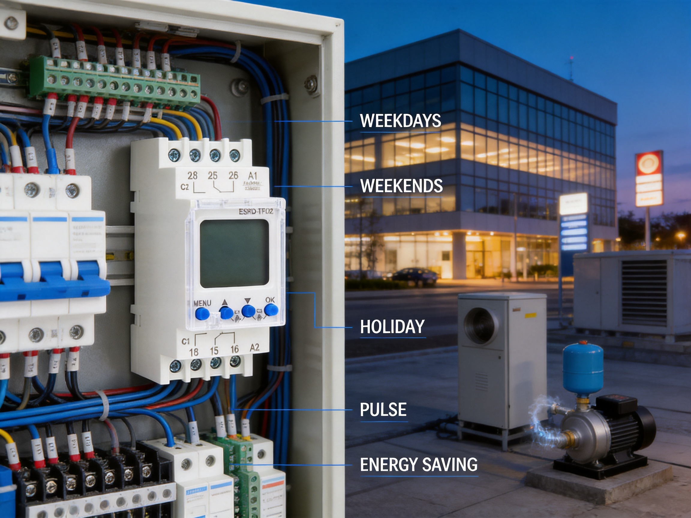
It is used to automate electrical control functions according to user-defined weekly, daily, or pulse schedules. Typical applications include lighting, ventilation, heating, pumps, signage, access interfaces, and other suitable control circuits.
The product title, description, and feature list identify it as a double-channel model, with an individual program assignable to each channel. However, one technical-data entry lists one channel. Buyers should confirm the exact model configuration, terminal arrangement, and current datasheet before ordering.
The information supplied includes two values: 90 programs in the technical table and 100 programs in the product content. This may reflect different revisions or a documentation inconsistency. The current program capacity should be confirmed with the manufacturer or distributor for the intended production version.
Yes. Pulse programming is listed as one of the supported program types. It can provide a timed impulse for suitable interfaces, relays, actuators, bells, or control inputs. The connected equipment must be compatible with the pulse behavior.
The internal lithium battery protects the real-time clock and stored settings when the external supply is interrupted. The stated power reserve is up to ten years. The output state during an outage depends on the device design and connected circuit, so the project manual should be consulted for the exact behavior.
It may control a suitable load within the applicable relay and utilization ratings, but motors and pumps can have high starting currents and inductive characteristics. In many cases, an intermediate contactor or relay is recommended. The installer must assess the load and follow the equipment manufacturer’s requirements.
The device has an IP20 protection degree and should therefore be installed inside a suitable protective enclosure. It should not be exposed directly to rain, water, or uncontrolled moisture. The enclosure must also maintain the required temperature and pollution conditions.
It is designed for two-module DIN-rail mounting. This allows installation in compatible distribution boards and control cabinets. The installer should confirm the available rail space and arrange wiring to maintain safe clearances and service access.
The stated operating modes are manual, automatic, and holiday. Automatic mode follows the stored schedule, manual mode allows operator control, and holiday mode provides temporary schedule behavior for planned absences or closures.
Yes. The product supports automatic summer/winter time switchover, and the function can also be turned off. The correct setting depends on the site’s local time policy.
Programming is performed using the four front-panel keys and the LCD display. The user sets the clock and date, selects the channel and program type, enters the required days and times, and chooses the desired operating mode. The exact menu sequence should be taken from the current operating manual.
The supplied technical information references IEC/EN 60730-1 and IEC/EN 60730-2-7. Buyers should request current conformity and certification documents for the exact model and market before installation.
The product is manufactured by Eastron Electronic Co., Ltd., an electrical-product and energy-measurement company headquartered in Jiaxing, Zhejiang, China. The company develops electricity meters, power analyzers, current sensors, communication modules, management systems, and related products.
The company reports research and development teams in China and the United Kingdom, cooperation with universities and institutions, an in-house laboratory for EMC, low-voltage, accuracy, and environmental tests, ISO 9001 quality management, patented hardware and software technologies, and experience supplying products to more than 50 countries.
The Pulse Program Double Channels Digital Weekly Time Switch is a compact and versatile solution for scheduled electrical control. Its combination of independent channel programming, weekly and daily schedules, pulse operation, holiday mode, automatic seasonal-time adjustment, manual override, LCD visibility, long battery reserve, and DIN-rail mounting gives it a broader capability than a basic mechanical timer or simple single-channel switch.
The device is particularly well suited to commercial buildings, retail facilities, residential common areas, agricultural installations, industrial control panels, public facilities, and other applications requiring dependable local scheduling. Its broad 24–264 V AC/DC supply range and 16 A/250 V AC relay rating increase application flexibility, while the compact two-module format helps conserve panel space.
Correct engineering remains essential. The specified load category must be respected, inductive and high-inrush loads may require an intermediate contactor, and the IP20 device must be installed in a suitable enclosure. The apparent discrepancies in the supplied channel and program-count information should also be confirmed before procurement.
From a manufacturing perspective, the product benefits from a company with experience in electrical measurement, embedded systems, control products, laboratory testing, international supply, and quality management. These strengths provide a useful foundation for consistent production and ongoing technical support. When applied within its ratings and configured carefully, the ESRD-TPD2 can provide a practical balance of scheduling flexibility, installation simplicity, operational continuity, and lifecycle value.
1. Product technical information for ESRD-TPD2 digital time switch, including electrical ratings, operating modes, mounting details, environmental limits, and referenced standards.
2. IEC/EN 60730-1, Automatic electrical controls for household and similar use—general requirements.
3. IEC/EN 60730-2-7, Particular requirements for timers and time switches.
4. Manufacturer-provided company information concerning research and development, laboratory testing, quality management, product scope, and international supply.
5. General electrical installation principles for DIN-rail control equipment, relay protection, contactor selection, enclosure protection, and load-compatibility assessment.
Your email address will not be published. Required fields are marked *

We develop and produce high performance electricity meters, power analyzers, current sensors, communication modules and management systems.
Address:NO. 52, Dongjin Road, Nanhu, Jiaxing, Zhejiang, China
Copyright @ Eastron Electronic Co., Ltd. All rights reserved
