

 English
 Español
 Deutsch
 中文简体


Product Consultation
Your email address will not be published. Required fields are marked *
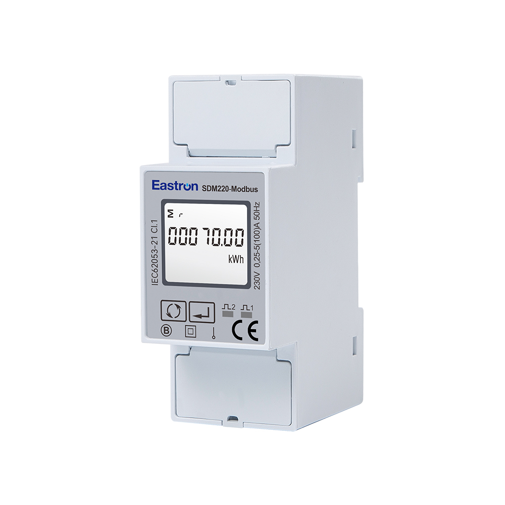
100A Single Phase Din Rail Multi-function Meter for EV Charging Metering
Aug 11,2022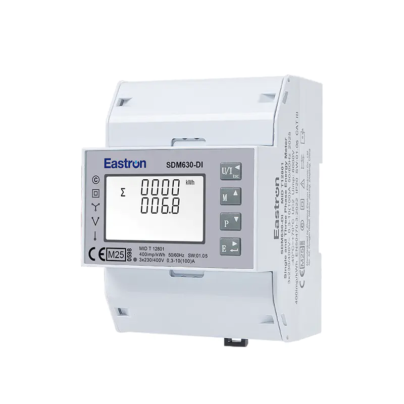
MID & UL Approved Three Phase Din Rail Type Multi-function Energy Meter for EV Charging Metering
Nov 24,2022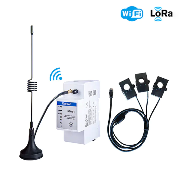
Wifi & LoRa Three Phase Din Rail Energy Meter for PV Metering
Sep 19,2025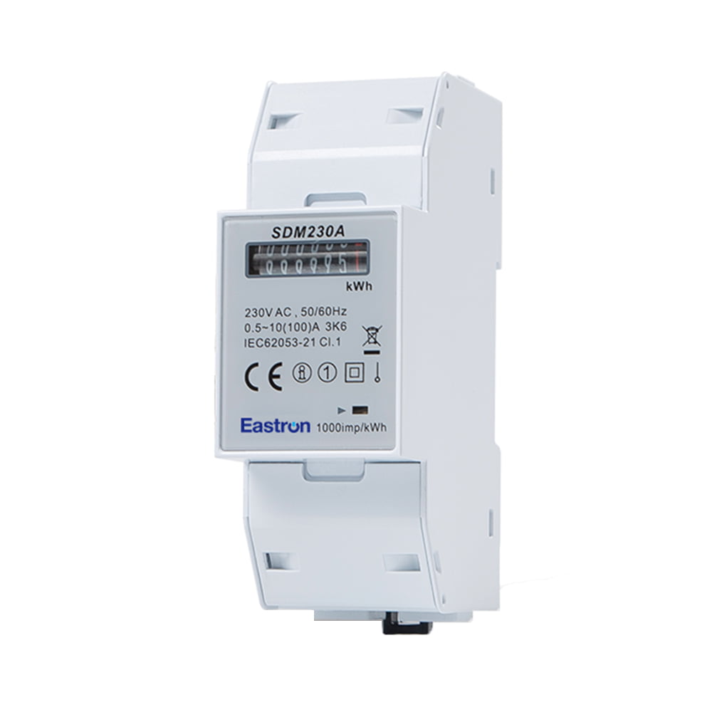
Analog Display 100A Din Rail Single Phase Electronic kWh meter with Pulse Output
Aug 11,2022
MID/RCM 100mA CT input Din Rail Single Phase Multi-function Solar PV /Zero Export Meter for PV Metering
Nov 24,2022
MID/UL CT Type Din Rail Three Phase Multi-function Energy Meter for EV Charging Metering
Nov 24,2022Content
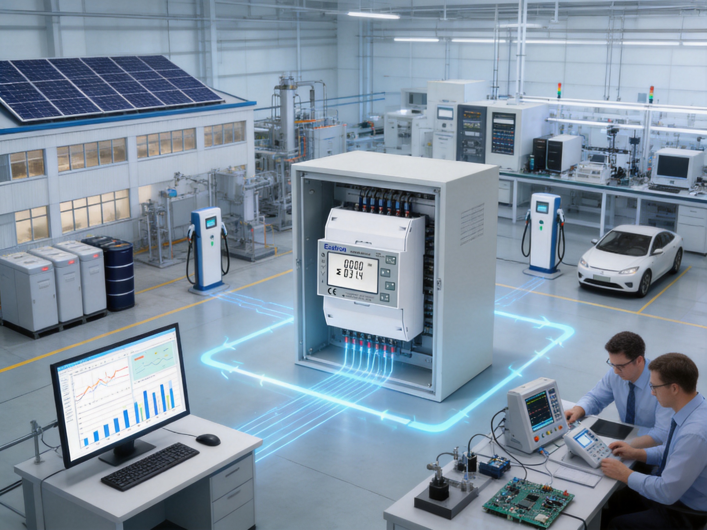
Modern electrical installations require more than a simple measurement of consumed kilowatt-hours. Commercial buildings, industrial facilities, renewable-energy systems, distribution panels, workshops, and infrastructure projects increasingly need accurate information about voltage, current, active power, reactive power, apparent power, power factor, frequency, demand, and imported or exported energy. They also need this information in a format that can be viewed locally and transferred to a building-management system, energy-management platform, or remote monitoring application.
The SDM630-Mbus V2 is designed for this role. It is a three-phase multifunction energy meter in a compact DIN rail enclosure, capable of directly measuring loads up to 100A without external current transformers in suitable installations. It supports 3P3W, 3P4W, and 1P2W electrical systems, provides two pulse outputs, and includes M-Bus communication according to EN13757. Its combination of direct-load capability, multifunction measurement, bidirectional energy recording, and communication functionality makes it a practical option for modern low-voltage distribution systems.
This article examines the meter’s operating concept, electrical capabilities, installation advantages, communication features, measurement functions, manufacturing strengths, and suitability for professional energy-management projects. It also explains how the product can compare favorably with more limited meters that provide only basic energy readings, require external CTs for ordinary loads, or lack a standard wired communication interface.
Energy monitoring is increasingly important because electricity costs, power-quality requirements, equipment reliability, and sustainability targets are closely connected. A basic electricity meter may indicate how much energy has been consumed, but it cannot always explain why consumption has changed or whether a system is operating efficiently.
A multifunction meter adds useful context to energy data. Voltage readings can reveal supply abnormalities. Current readings show loading on each phase. Active power indicates the rate of real energy consumption. Reactive power helps identify inductive or capacitive behavior. Apparent power shows the total electrical burden placed on the supply. Power factor indicates how effectively electrical current is being converted into useful work. Frequency confirms the stability of the supply waveform, while demand measurements can help users understand peak loading over a selected period.
These measurements are valuable in many applications. A factory may use them to monitor production machinery and identify overloaded circuits. A commercial building may use them to compare tenant consumption or improve the operation of HVAC systems. A data room may use current and power readings to balance loads across phases. A solar or storage installation may need to record energy flow in both directions. An electrical contractor may install the meter in a distribution board to provide a central view of system performance.
The SDM630-Mbus V2 combines these functions in one instrument. Instead of installing separate meters for voltage, current, power factor, active energy, and reactive energy, a single device can present a broad set of electrical parameters. This reduces panel complexity and simplifies the collection of data for energy-management systems.
The SDM630-Mbus V2 is a three-phase multifunction energy meter intended for DIN rail mounting. It is four modules wide, with an overall width of 72 mm. This format allows the meter to be installed in standard electrical distribution enclosures alongside circuit protection, switching, control, and communication equipment.
The meter can measure three-phase three-wire systems, three-phase four-wire systems, and single-phase two-wire systems. This flexibility allows one product family to serve multiple project requirements. In a three-phase four-wire installation, the meter can monitor phase-to-neutral systems. In a three-phase three-wire installation, it can be applied to systems without a neutral conductor. Its ability to work in a single-phase two-wire arrangement also makes it useful for smaller installations and standardized panel designs.
The meter is rated for direct connection to loads of up to 100A. The stated rated current is 10A, while the maximum current is 100A, the minimum current is 0.5A, and the starting current is 40mA. Direct connection can be especially useful where the load remains within the product’s specified operating range and local installation rules permit this arrangement.
Because external CTs are not required for suitable loads up to 100A, installation can be simpler than with transformer-operated meters. The installer does not need to select, mount, wire, and verify separate current transformers. This can reduce the number of components in the panel and help avoid CT-related polarity, ratio, and secondary-circuit errors.
In addition to its local display and measurement functions, the SDM630-Mbus V2 provides two pulse outputs and an M-Bus interface. The pulse outputs can be used for energy pulse collection, while M-Bus communication allows the meter to exchange data with compatible master devices and metering systems.
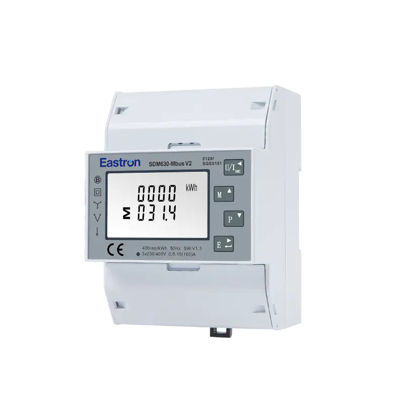
Mbus 100A Din Rail Three Phase Multi-function Energy Meter
Voltage and current are the foundation of electrical system monitoring. The meter supports a rated voltage of 230V line-to-neutral or 120V line-to-neutral, with an operational voltage range of 80% to 120% of the rated value. Current measurement is designed for direct-load applications, with a maximum current of 100A.
Accurate voltage and current information helps users evaluate the condition of each phase. Unequal phase currents may indicate unbalanced loads, poor distribution design, or changes in operating equipment. Voltage variation may point to upstream supply conditions, loose connections, long cable runs, or other system issues. By collecting these values continuously, an energy-management system can provide better information than periodic manual readings.
Active power, measured in watts, represents the power converted into useful work, heat, light, or mechanical output. Reactive power, measured in var, is associated with the energy exchange between the supply and reactive components such as motors, transformers, and capacitors. Apparent power, measured in VA, represents the combined electrical loading created by active and reactive components.
The meter provides measurement of W, Var, and VA. The stated accuracy for active power, reactive power, and apparent power is ±1%. These measurements allow engineers to investigate the relationship between useful output and total electrical demand.
For example, a motor installation may consume a moderate amount of active power but draw substantially more apparent power because of reactive behavior. This can increase current in cables and transformers even when useful production output has not changed. Monitoring all three power values can help users decide whether load balancing, equipment replacement, or power-factor correction should be considered.
Power factor is an important indicator of electrical efficiency. A lower power factor generally means that more current is required to deliver the same amount of active power. The meter measures power factor with a stated accuracy of ±1% and measures frequency with a stated accuracy of ±0.2%.
Frequency information can help verify that the supply remains within expected operating conditions. It can also assist in the analysis of generator systems, isolated networks, and power-conversion equipment. When voltage, current, power factor, and frequency are viewed together, maintenance personnel can obtain a more complete picture of system behavior.
The SDM630-Mbus V2 measures active energy in kilowatt-hours and reactive energy in kilovar-hours. Active energy accuracy is specified as Class 1.0 according to IEC 62053-21 and Class B according to EN50470-1/3. Reactive energy is specified as Class 2 according to IEC 62053-23.
The meter supports imported and exported energy measurement. This bidirectional capability is significant in installations where energy can flow in both directions, such as photovoltaic systems, battery-storage systems, microgrids, combined heat and power installations, and sites with on-site generation. A unidirectional meter may not provide a complete record in these applications, while bidirectional measurement can distinguish energy received from the network from energy delivered back to it.
Maximum demand can also be measured over preset periods of up to 60 minutes. Demand data is useful because electricity tariffs may be influenced by peak power rather than total energy alone. Facility operators can use demand information to identify high-load periods, coordinate equipment startup, and develop load-management strategies.
Measurement accuracy is one of the most important considerations when selecting an energy meter. The SDM630-Mbus V2 provides stated accuracy specifications for its primary electrical parameters. Voltage and current are specified at ±0.5%. Frequency is specified at ±0.2%. Power factor, active power, reactive power, and apparent power are each specified at ±1%.
Energy accuracy is expressed through recognized standards. The Class 1.0 designation under IEC 62053-21 indicates the stated active-energy performance class of the meter. The Class B designation under EN50470-1/3 provides another reference for active-energy measurement performance. Reactive energy is identified as Class 2 under IEC 62053-23.
Standards-based specifications help engineers compare products using a common technical language. They are especially important when meters are used for internal cost allocation, energy-performance analysis, equipment verification, or integration into a larger metering system. The appropriate meter class must always be evaluated against the project’s legal, billing, and regulatory requirements, but clearly stated performance information gives designers a reliable starting point.
| Measured Parameter | Stated Accuracy or Classification | Typical Application Value |
|---|---|---|
| Voltage | ±0.5% | Supply verification and phase-condition monitoring |
| Current | ±0.5% | Load monitoring and phase balancing |
| Frequency | ±0.2% | Supply and generator monitoring |
| Power factor | ±1% | Efficiency review and reactive-load analysis |
| Active power | ±1% | Real-time load and equipment monitoring |
| Reactive power | ±1% | Motor, transformer, and compensation analysis |
| Apparent power | ±1% | Assessment of total electrical loading |
| Active energy | Class 1.0 IEC 62053-21; Class B EN50470-1/3 | Energy accounting and consumption analysis |
| Reactive energy | Class 2 IEC 62053-23 | Reactive-energy monitoring |
One of the product’s main advantages is its ability to connect directly to loads up to 100A. Many multifunction meters designed for higher-current distribution systems use external current transformers. CTs are valuable for large installations, but they add hardware, wiring, configuration, and inspection requirements.
A direct-connected meter can be more efficient for small and medium-sized feeders. The installer can connect the current path through the meter according to the approved wiring diagram, without adding a separate CT assembly. This may reduce panel space requirements and simplify the bill of materials. It can also make commissioning more straightforward because the installer does not need to confirm CT ratios or correct CT secondary polarity.
Eliminating external CTs may also improve data consistency in applications where the load is comfortably within the 100A direct-measurement range. A CT-based system depends on the relationship between the meter configuration and the transformer ratio. If the ratio is entered incorrectly, energy and power readings can be scaled incorrectly. Direct measurement avoids this particular configuration step.
Direct connection does not mean that every 100A application is automatically suitable. The installation must comply with the meter’s electrical specifications, local wiring regulations, conductor requirements, protective-device ratings, isolation procedures, and environmental conditions. The installer must also verify that the expected continuous and peak current remains within the permitted range. Correct terminal tightening, overcurrent protection, and safe working practices remain essential.
Electrical networks are not all wired in the same way. Some installations use a neutral conductor, while others use three-wire systems. Some projects require three-phase monitoring, while others need a compact device that can also be used for single-phase circuits. Supporting 3P3W, 3P4W, and 1P2W arrangements gives the SDM630-Mbus V2 broader project compatibility.
Three-phase four-wire systems are common in commercial and industrial distribution, especially where line-to-neutral loads are present. Three-phase three-wire systems may be found in particular motor, industrial, and older distribution arrangements. Single-phase two-wire operation can support smaller applications or allow a common meter platform to be used across different panel types.
This flexibility can benefit equipment distributors and system integrators. Instead of maintaining separate product families for each wiring method, a multifunction meter with multiple system configurations can simplify product selection and inventory planning. It can also make replacement and expansion projects easier when the exact arrangement differs between sites.
Before installation, the wiring system must be identified correctly and the meter must be configured for the intended connection. The wiring diagram supplied for the product should be followed carefully. Incorrect phase sequence, neutral connection, or current-path wiring can lead to inaccurate readings or unsafe operation.
M-Bus is a communication technology developed for meter reading and building services. The SDM630-Mbus V2 provides an M-Bus interface according to EN13757-3. This allows measured data to be transferred to a compatible M-Bus master, data concentrator, automation controller, or energy-management platform.
The M-Bus communication address range is 1 to 250. The supported baud rates range from 300bps to 9600bps. Parity can be configured as none, odd, or even, with none specified as the default. One or two stop bits are supported. The stated maximum transmission distance is 1000 meters, although the actual usable distance depends on cable type, network topology, master capability, electrical loading, installation conditions, and applicable M-Bus design rules.
M-Bus is particularly useful when multiple meters must be collected in one location. A building may contain meters for separate floors, tenant areas, heat pumps, lighting systems, electric-vehicle chargers, and renewable-energy equipment. Instead of reading each device manually, a central system can retrieve the measurements over the communication network.
Data collection improves the value of the meter. Local display readings are useful for commissioning and maintenance, but automated communication supports trend analysis, alarm generation, reporting, tenant allocation, and energy benchmarking. It also reduces the need for personnel to access electrical cabinets repeatedly.
The use of a standard metering communication interface is an advantage over basic meters that provide only a display or a pulse output. A pulse output can communicate accumulated energy, but it generally does not provide the same breadth of instantaneous electrical information as a digital data interface. M-Bus can therefore support a more complete monitoring solution.
The meter includes two pulse outputs for imported and exported energy. Pulse outputs are widely used in energy-monitoring systems because they provide a simple way to transmit accumulated energy information to external equipment.
One output can be assigned to imported energy and another to exported energy, depending on system configuration and project requirements. These outputs can be connected to a pulse counter, controller, data logger, or building-management system that accepts the appropriate pulse signal. They may be useful when an existing installation already uses pulse-based data collection or when a simple backup measurement channel is required.
The combination of pulse outputs and M-Bus communication provides design flexibility. M-Bus can deliver a larger set of measurements to a central system, while pulses can provide a straightforward energy-total signal to another device. This can support layered monitoring architectures in which a primary energy-management system and a secondary control or verification system use the same meter.
Pulse wiring and pulse-value configuration must be checked during commissioning. The receiving device must be compatible with the output characteristics, and the installer should verify that the pulse weighting, energy direction, and accumulated totals are interpreted correctly.
Space is often limited inside distribution boards. Protection devices, contactors, terminal blocks, surge protection, communication modules, and control equipment all compete for available DIN rail space. At four modules or 72 mm wide, the meter offers a compact footprint for the number of functions it provides.
A compact design can offer several practical benefits. It may reduce the size of a new panel, allow additional circuits to be added to an existing enclosure, and simplify the layout of retrofit projects. It can also improve accessibility when the meter is positioned next to the circuit it monitors.
The front-panel arrangement allows users to view electrical parameters and operate configuration controls locally. The product information states that electronic parameters can be set using the buttons and that configuration is password protected. Password protection helps prevent accidental or unauthorized changes to important settings such as system type, communication address, and other operating parameters.
Local configuration is valuable during commissioning because technicians can verify settings without requiring a separate programming interface. At the same time, password protection provides a basic control layer for installations where multiple people may have access to the panel.
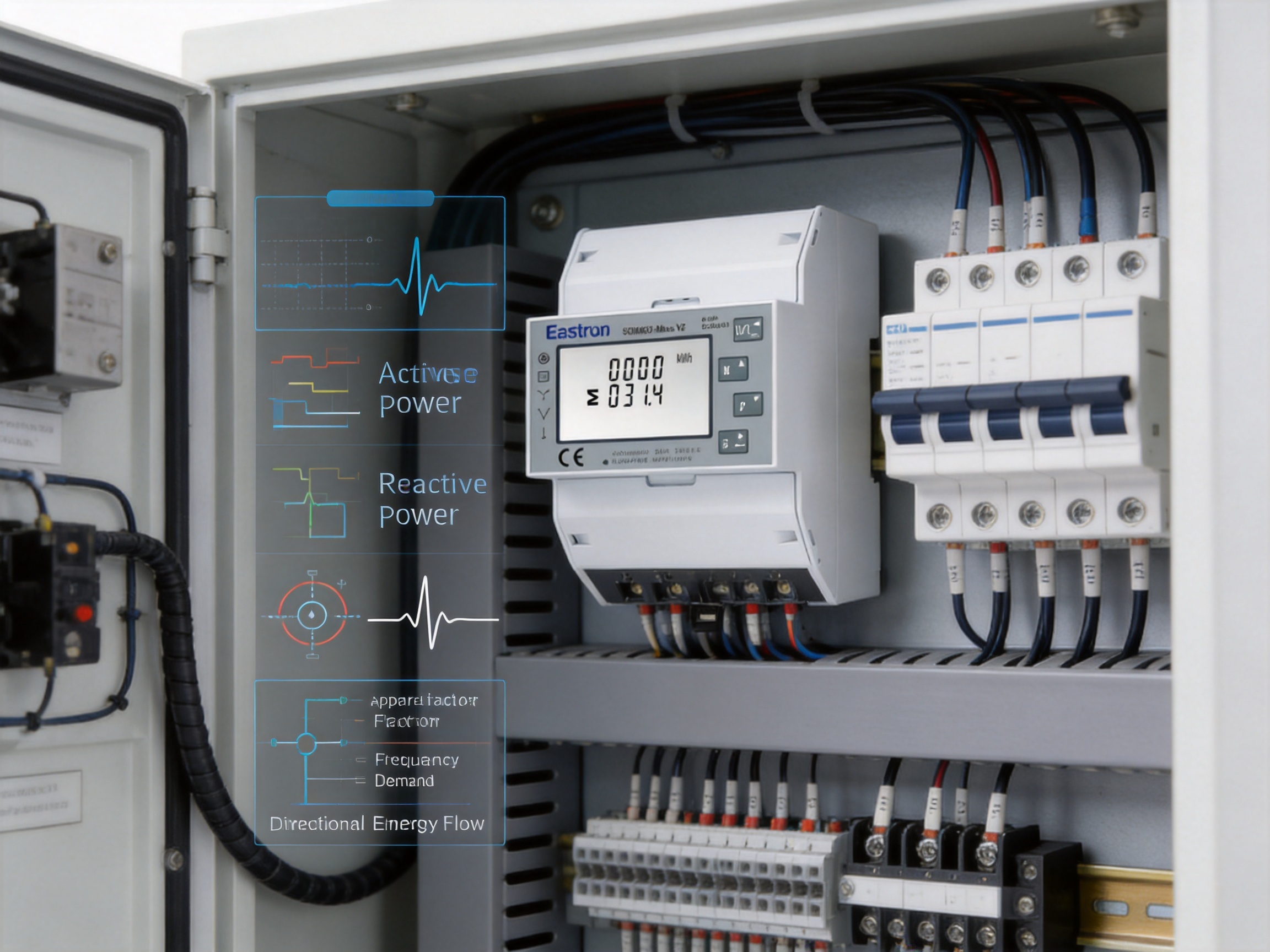
Energy is no longer consumed only in one direction. Rooftop photovoltaic systems, battery storage, electric-vehicle charging infrastructure, backup generators, and microgrids can all change the direction and timing of power flow. A meter installed at a grid connection or sub-distribution point may need to record energy imported from the network as well as energy exported to it.
The SDM630-Mbus V2 supports bidirectional measurement of active and reactive energy. This makes it suitable for monitoring sites where generation and consumption coexist. A facility operator can compare energy purchased from the grid with energy returned to the grid. A solar installer can review on-site production behavior and export periods. An energy manager can evaluate whether storage is reducing peak imports or shifting energy use to more favorable periods.
Bidirectional measurement is also useful for commissioning. If the expected direction of energy flow does not match the meter reading, the installer can investigate phase wiring, polarity, system configuration, or generation behavior. Clear import and export information can reduce uncertainty during system testing.
Bidirectional functionality should not be confused with legal settlement approval for every possible application. If a meter is intended for regulated billing, revenue settlement, or a jurisdiction-specific approval, the project designer must confirm that the exact model and installation meet the applicable requirements. For technical monitoring and internal energy management, however, bidirectional measurement provides substantial value.
Energy meters differ significantly in their measurement depth, installation method, communication options, and physical format. A basic single-function meter may provide only total active energy. A current meter may display amperes but not energy. A power monitor may provide instantaneous readings without storing or communicating accumulated totals. A CT-operated meter may support high currents but require additional components even for moderate loads.
The SDM630-Mbus V2 is differentiated by combining multiple functions in one DIN rail instrument. Its key benefits include:
Direct measurement up to 100A for suitable applications, reducing the need for external CTs.
Compatibility with 3P3W, 3P4W, and 1P2W systems.
Measurement of voltage, current, active power, reactive power, apparent power, power factor, frequency, demand, active energy, and reactive energy.
Bidirectional monitoring of imported and exported energy.
Two pulse outputs for energy pulse collection.
M-Bus communication according to EN13757-3.
A compact four-module, 72 mm DIN rail enclosure.
Local button-based configuration protected by a password.
These features can reduce the need to combine several separate devices. Fewer components may simplify panel design, wiring, ordering, testing, and maintenance. The best choice still depends on project requirements, but a multifunction meter can offer a better balance between capability and installation effort than a basic energy counter.
| Design Consideration | Limited Basic Meter | SDM630-Mbus V2 Approach |
|---|---|---|
| Energy direction | Often focused on one direction | Bidirectional imported and exported energy measurement |
| Measured parameters | May provide energy only | Energy, power, voltage, current, frequency, power factor, demand, and more |
| Current connection | May require external CTs | Direct connection up to 100A for suitable installations |
| Wiring compatibility | May support one system type | 3P3W, 3P4W, and 1P2W operation |
| Communication | Display or pulse only | Two pulse outputs plus M-Bus interface |
| Panel integration | Varies by product | Four-module, 72 mm DIN rail form factor |
Product performance depends not only on the specification sheet but also on the manufacturing system behind the product. Eastron Electronic Co., Ltd. develops and produces electricity meters, power analyzers, current sensors, communication modules, and energy-management products. Its broader product portfolio indicates experience across measurement hardware, embedded electronics, communications, and energy applications.
The company maintains development teams in China and the United Kingdom. This combination supports product development across different technical and market environments. Cooperation with universities and institutions is also identified as part of the company’s approach to advancing electricity-measurement technologies.
Research and development is especially important for multifunction meters because the product must combine analog measurement, signal processing, embedded firmware, display operation, communication protocols, memory management, protective design, and mechanical integration. A weakness in any one of these areas can affect the overall user experience. Stable measurement requires carefully designed sensing circuits and calibration processes, while reliable communication requires robust firmware and protocol implementation.
The company states that it has established a professional laboratory capable of performing electromagnetic compatibility, low-voltage directive, accuracy, and environmental tests. These test areas are directly relevant to DIN rail energy meters. EMC testing helps assess resistance to interference and unwanted emissions. Low-voltage testing supports electrical safety evaluation. Accuracy testing verifies measurement performance. Environmental testing examines operation under specified temperature, humidity, and related conditions.
Testing against IEC, EN, GB, and UL standards provides a framework for evaluating products for different markets and applications. The exact certification requirements remain dependent on the model, destination market, and intended use, but an in-house professional laboratory can help the manufacturer identify design issues earlier and maintain more consistent production controls.
Energy meters rely on precise relationships between voltage, current, phase angle, and time. Manufacturing must therefore control component tolerances, sensing paths, circuit-board assembly, firmware algorithms, and calibration data. Accuracy testing is not limited to checking a single value; it generally requires evaluation across relevant operating points and conditions.
A professional laboratory allows the manufacturer to conduct repeatable verification during product development and production support. This can improve the consistency of meters supplied for larger projects, where differences between individual units must remain within the specified performance range.
Distribution boards can contain contactors, variable-frequency drives, switching power supplies, relays, and other sources of electrical noise. A meter used in such an environment must be designed with suitable circuit protection, filtering, grounding strategy, enclosure considerations, and firmware behavior.
Environmental testing is also significant. Energy meters may be installed in plant rooms, service cabinets, commercial electrical rooms, or outdoor-rated enclosures where temperature and humidity vary. Testing helps evaluate whether the product continues to operate as intended under specified conditions. Installation must still follow the product’s environmental limits and applicable enclosure requirements.
Eastron operates under an ISO 9001 quality management system, according to the supplied company information. A quality-management system provides a structured framework for design control, purchasing, production, inspection, corrective action, and continuous improvement.
For an energy meter, production control can include component verification, automated or semi-automated assembly, solder-joint inspection, firmware loading, functional testing, display verification, communication testing, terminal inspection, and final measurement checks. These controls help reduce variation and support traceability through the manufacturing process.
The company also reports production approval by SGS according to MID standards. Project teams should verify the exact approval status of the specific product variant and intended application, but this manufacturing background demonstrates attention to formal quality and metrology requirements.
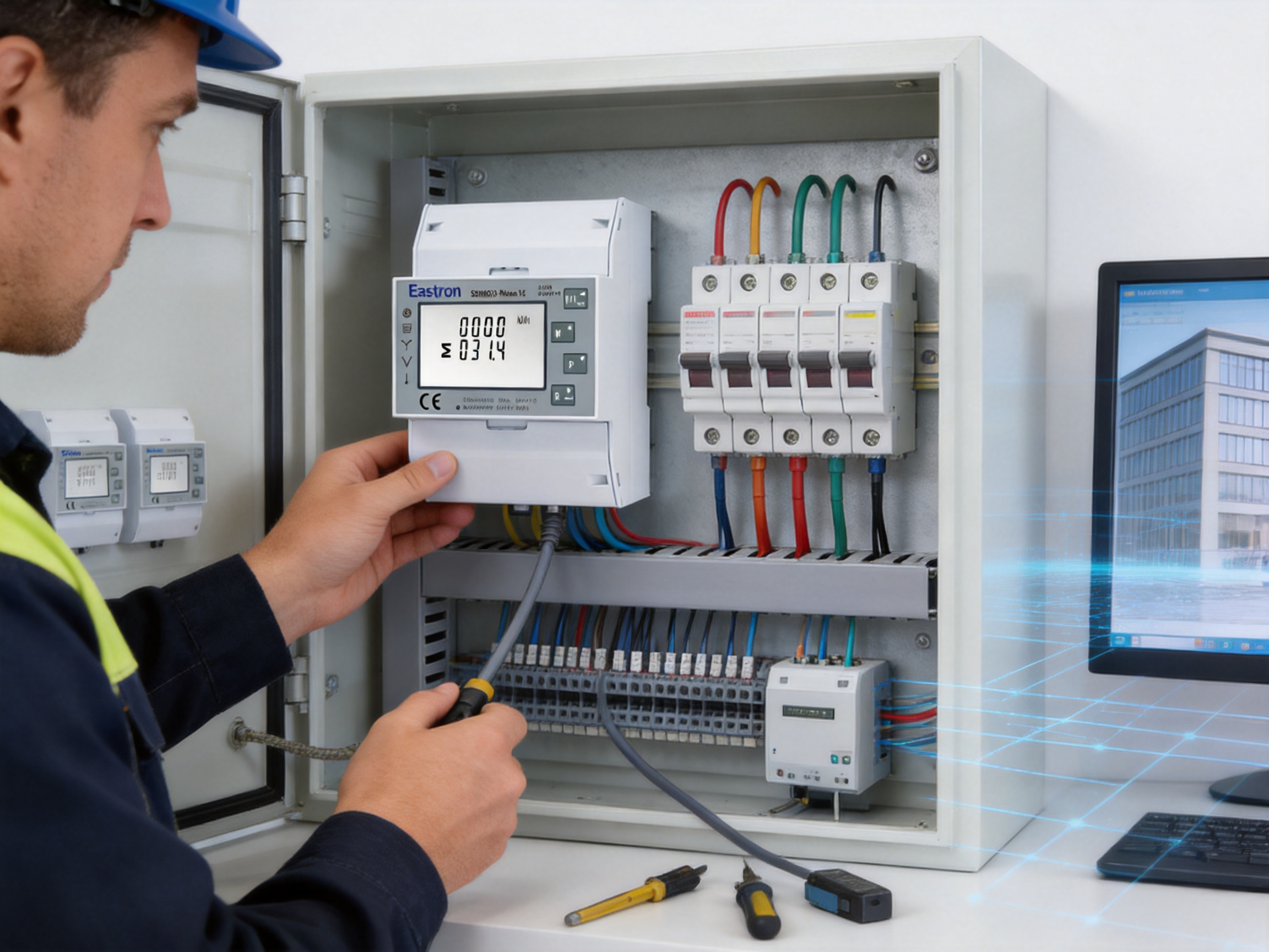
Commercial buildings often contain multiple tenants, departments, or services that need separate energy visibility. A meter can be installed at distribution levels serving offices, retail areas, common facilities, lighting systems, HVAC equipment, or parking infrastructure.
By collecting active and reactive energy data through M-Bus, a building-management system can compare consumption over time. Voltage, current, power factor, and demand readings can help facility operators identify abnormal conditions or inefficient operating schedules.
Industrial facilities need to understand both energy consumption and electrical loading. Motors, pumps, compressors, heaters, welding equipment, and production lines may have very different operating profiles. A multifunction meter can monitor feeders or equipment groups without requiring a separate instrument for each parameter.
Reactive-power and power-factor information may be useful in facilities with large motor loads. Demand readings can help identify production periods that create high peak loading. Phase-current information can support load balancing and maintenance planning.
Photovoltaic systems and battery-storage installations can import energy from the grid and export energy to it. Bidirectional measurement provides a way to observe these flows at a selected point in the electrical system.
When combined with M-Bus data collection, the meter can contribute to a broader energy-management strategy. Data from the meter may be compared with inverter output, battery state of charge, building demand, and grid import records. This can help users evaluate self-consumption, export periods, and peak-reduction performance.
Electric-vehicle charging loads can be substantial and may vary significantly throughout the day. A meter installed on a charging feeder can measure current, active power, energy, power factor, and demand. This information can help operators understand the effect of charging on the building supply and assess whether load management is needed.
For charging systems with energy flowing only from the building to the vehicle, unidirectional readings may be sufficient. However, sites that combine charging, solar generation, or battery storage can benefit from bidirectional measurement at the main connection or energy-management point.
Submetering divides a larger electricity supply into measurable areas or loads. This can support internal cost allocation, operational benchmarking, tenant reporting, and energy-efficiency programs. Because the SDM630-Mbus V2 measures multiple electrical parameters and communicates through M-Bus, it can serve as a submetering device in suitable technical and regulatory contexts.
For formal billing or legal metrology, the project owner must confirm all applicable requirements. For internal allocation and performance monitoring, the meter’s energy accuracy and communication functions can provide a practical foundation.
Installation should be performed by qualified personnel who understand the electrical system and local safety requirements. Before work begins, the circuit must be isolated and verified as de-energized where required. Suitable protective equipment, conductor sizes, terminal accessories, and overcurrent protection must be selected for the application.
The installer should identify the system type: 3P3W, 3P4W, or 1P2W. The voltage level must be checked against the rated and operational voltage specifications. The expected current must be confirmed to remain within the direct-measurement range. Phase conductors, neutral conductors where applicable, and output wiring must be connected according to the approved wiring diagram.
After installation, the following checks are recommended:
Verify that the meter is securely mounted on the DIN rail.
Confirm that conductors are connected to the correct terminals.
Check phase sequence and polarity.
Confirm that the selected system configuration matches the actual wiring.
Verify voltage readings before applying significant load.
Compare current readings with an independent reference instrument where appropriate.
Check active-power direction and confirm imported or exported energy behavior.
Configure the communication address and baud rate if M-Bus integration requires adjustment.
Test both pulse outputs with the receiving equipment.
Record the initial energy readings and configuration settings.
Confirm that password protection is enabled according to the project’s access-control procedure.
These steps help identify wiring and configuration errors before the system is placed into regular operation. They also create useful commissioning records for future maintenance.
The meter can function as part of a larger energy-management architecture. A typical system may include multiple field meters, an M-Bus master, a gateway, a data server, visualization software, alarms, and reporting tools. The SDM630-Mbus V2 provides field-level measurements, while the higher-level system organizes and interprets the information.
When several meters are connected to one M-Bus network, each device should have a unique address. Network design must consider cable length, master capacity, signal quality, installation topology, and the total number of connected devices. Communication settings should be documented and tested during commissioning.
Data can be used for daily, weekly, monthly, or annual comparisons. A facility may establish a baseline for normal consumption and then create alarms for unexpected current, power, voltage, or demand conditions. Historical trends can reveal seasonal changes, equipment degradation, production anomalies, and the results of energy-efficiency measures.
The meter’s broad measurement range can make the data more useful than a simple kWh total. For example, an energy increase accompanied by a lower power factor may indicate a change in motor operation. A current imbalance may suggest an unevenly loaded distribution system. A rise in apparent power without a similar rise in active power may indicate an increase in reactive demand.
System designers benefit from products that combine technical capability with straightforward integration. The SDM630-Mbus V2 provides several design advantages.
First, the direct 100A connection can reduce the need for external components in many low-voltage applications. This can simplify single-line diagrams, panel layouts, procurement, and installation labor.
Second, the support for several wiring configurations gives designers more flexibility when creating standardized panel designs. One product can be considered for single-phase and different three-phase arrangements, subject to correct configuration and application verification.
Third, the combination of local display, pulse outputs, and M-Bus communication supports different levels of system complexity. A small installation may use the display and pulse output, while a larger building may connect the same product to a centralized M-Bus network.
Fourth, the compact DIN rail format makes the meter easier to incorporate into crowded electrical panels. Space savings can be particularly important in retrofit projects where the existing enclosure cannot be enlarged.
Fifth, a broad measurement set allows one device to support energy accounting, operational monitoring, maintenance analysis, and demand review. This can reduce the number of instruments required for a complete monitoring point.
A technical specification has value only when the product can deliver consistent performance in real installations. Energy meters operate continuously, often for many years, and may be connected to systems where incorrect data can affect operational decisions. Manufacturing quality therefore influences measurement reliability, communication stability, safety, and service life.
Eastron’s reported laboratory capabilities in EMC, LVD, accuracy, and environmental testing are aligned with the main technical risks of electronic energy meters. Its product development experience across electricity meters, power analyzers, sensors, communications, and management systems supports a wider understanding of energy-measurement applications.
Research and development resources in China and the United Kingdom can contribute to product refinement and market adaptation. Cooperation with universities and institutions may also support new measurement technologies and improved embedded designs. Patented software, embedded-software, and hardware technologies, as reported by the company, indicate a focus on developing proprietary technical capabilities rather than relying only on standard assembly.
International supply experience is another practical strength. The company states that its products and services have been supplied to more than 50 countries across Europe, Asia-Pacific, America, the Middle East, and Africa. This type of market exposure can help a manufacturer understand different installation practices, communication requirements, standards environments, and customer expectations.
The SDM630-Mbus V2 is a strong candidate when the application requires direct measurement up to 100A, three-phase multifunction measurement, bidirectional energy monitoring, and M-Bus communication in a compact DIN rail format.
It is particularly appropriate when:
The monitored load is within the direct-current specification.
The system may be 3P3W, 3P4W, or 1P2W.
Users need more than a simple energy total.
Imported and exported energy must be distinguished.
The installation uses or plans to use an M-Bus network.
Two energy pulse outputs are useful for control or backup data collection.
Panel space is limited.
Local display and password-protected configuration are desired.
A project requires a manufacturer with experience in energy measurement, communications, testing, and international supply.
The product may not be the correct choice for every application. Systems with currents above 100A may require CT-operated equipment. Projects requiring specialized revenue-metering approvals, advanced power-quality analysis, harmonic recording, Ethernet communication, or particular protection functions may need another model or an additional device. Careful review of the complete project specification is essential.
Routine maintenance should include visual inspection, terminal-condition checks, communication verification, and comparison of readings with expected operating conditions. The meter itself has no need for mechanical adjustment during normal operation, but the surrounding electrical installation should be inspected according to site procedures.
Unexpected changes in current, power factor, demand, or energy direction should be investigated rather than ignored. A sudden change may result from new equipment, a wiring modification, a failed sensor in another system, a communication issue, or an actual change in electrical behavior.
Communication records should include the meter address, network location, baud rate, connected master, pulse assignments, and configuration date. If a meter is replaced, these details can speed up recommissioning and reduce downtime.
Energy data should also be backed up or transferred to a central system where possible. Local display readings are useful, but historical information is more valuable when it is preserved and analyzed over time. Trends can support maintenance planning and provide evidence of energy-saving improvements.
It is a DIN rail three-phase multifunction energy meter with direct-load measurement up to 100A for suitable applications. It measures electrical quantities including voltage, current, active power, reactive power, apparent power, power factor, frequency, demand, active energy, and reactive energy.
Yes. The product information identifies support for 1P2W as well as 3P3W and 3P4W systems. The meter must be wired and configured correctly for the selected system type.
For suitable direct-connected installations within the product’s specified current range, external CTs are not required. The maximum current is stated as 100A. The installer must verify that the actual continuous and peak load, conductors, protection, and local regulations are appropriate for direct connection.
The stated rated current is 10A, while the maximum current is 100A, the minimum current is 0.5A, and the starting current is 40mA.
The stated rated voltage is 230V line-to-neutral or 120V line-to-neutral. The operational voltage range is 80% to 120% of the rated voltage.
Yes. The meter supports bidirectional measurement and can measure active and reactive energy imported or exported by the installation.
The SDM630-Mbus V2 provides M-Bus communication according to EN13757-3. It also provides two pulse outputs. Other versions in the wider product family may use RS485 Modbus, Ethernet Modbus TCP, tariffs, or digital inputs, so the exact model designation should be verified before ordering.
Two pulse outputs are available. They can be used for imported and exported energy pulse collection according to the selected configuration and project requirements.
The stated M-Bus communication address range is 1 to 250. The specified baud-rate range is 300bps to 9600bps.
The stated maximum transmission distance is 1000 meters. Actual performance depends on the network master, cable, topology, number of devices, electrical loading, and installation conditions.
The meter is four modules wide, equivalent to 72 mm, and is designed for DIN rail installation.
Yes. The product information states that electronic parameters can be configured using the buttons and that configuration is password protected.
Active energy is specified as Class 1.0 under IEC 62053-21 and Class B under EN50470-1/3. Reactive energy is specified as Class 2 under IEC 62053-23.
Suitability depends on the jurisdiction, application, approval status of the exact model, installation method, and applicable legal-metrology requirements. The project owner should verify these conditions before using the meter for regulated billing or revenue settlement.
It measures a broader set of electrical parameters, supports bidirectional energy measurement, works with several wiring systems, provides two pulse outputs, includes M-Bus communication, and can directly measure up to 100A in suitable installations. These functions support more detailed energy and electrical-system analysis.
The SDM630-Mbus V2 is designed for projects that need more complete electrical information than a basic energy counter can provide. Its direct 100A measurement capability can simplify suitable installations by avoiding external CTs. Its support for 3P3W, 3P4W, and 1P2W systems gives designers flexibility. Its measurements cover voltage, current, power, power factor, frequency, demand, active energy, and reactive energy, while bidirectional measurement supports systems with on-site generation or storage.
The product’s communication design is equally important. Two pulse outputs provide a simple energy-data channel, and M-Bus EN13757-3 communication allows the meter to become part of a larger metering network. The compact four-module DIN rail form factor helps conserve panel space, and password-protected local configuration supports controlled commissioning.
Behind the product is a manufacturer with experience in electricity meters, power analyzers, sensors, communications, and energy-management solutions. Its reported research and development resources, professional testing laboratory, ISO 9001 quality-management system, standards-oriented testing capabilities, and international supply experience provide important support for product reliability and project deployment.
For commercial, industrial, renewable-energy, submetering, and infrastructure applications within its specified electrical range, this meter offers a balanced combination of measurement depth, installation efficiency, communication flexibility, and compact mechanical design. Proper system selection, wiring, commissioning, and regulatory verification remain essential, but the product provides a strong technical foundation for modern energy monitoring.
IEC 62053-21, Electricity Metering Equipment: Particular Requirements for Static Meters for Active Energy.
IEC 62053-23, Electricity Metering Equipment: Particular Requirements for Static Meters for Reactive Energy.
EN50470-1, Electricity Metering Equipment: General Requirements, Tests, and Test Conditions.
EN50470-3, Electricity Metering Equipment: Particular Requirements for Static Meters for Active Energy.
EN13757-3, Communication Systems for Meters and Remote Reading of Meters: Application Protocols.
ISO 9001, Quality Management Systems: Requirements.
SDM630-Mbus V2 Product Technical Information, electrical characteristics, communication specifications, and installation data.
Manufacturer-provided information regarding product development, laboratory testing, quality management, research and development, and international supply capability.
Your email address will not be published. Required fields are marked *

We develop and produce high performance electricity meters, power analyzers, current sensors, communication modules and management systems.
Address:NO. 52, Dongjin Road, Nanhu, Jiaxing, Zhejiang, China
Copyright @ Eastron Electronic Co., Ltd. All rights reserved
