

 English
 Español
 Deutsch
 中文简体


Product Consultation
Your email address will not be published. Required fields are marked *
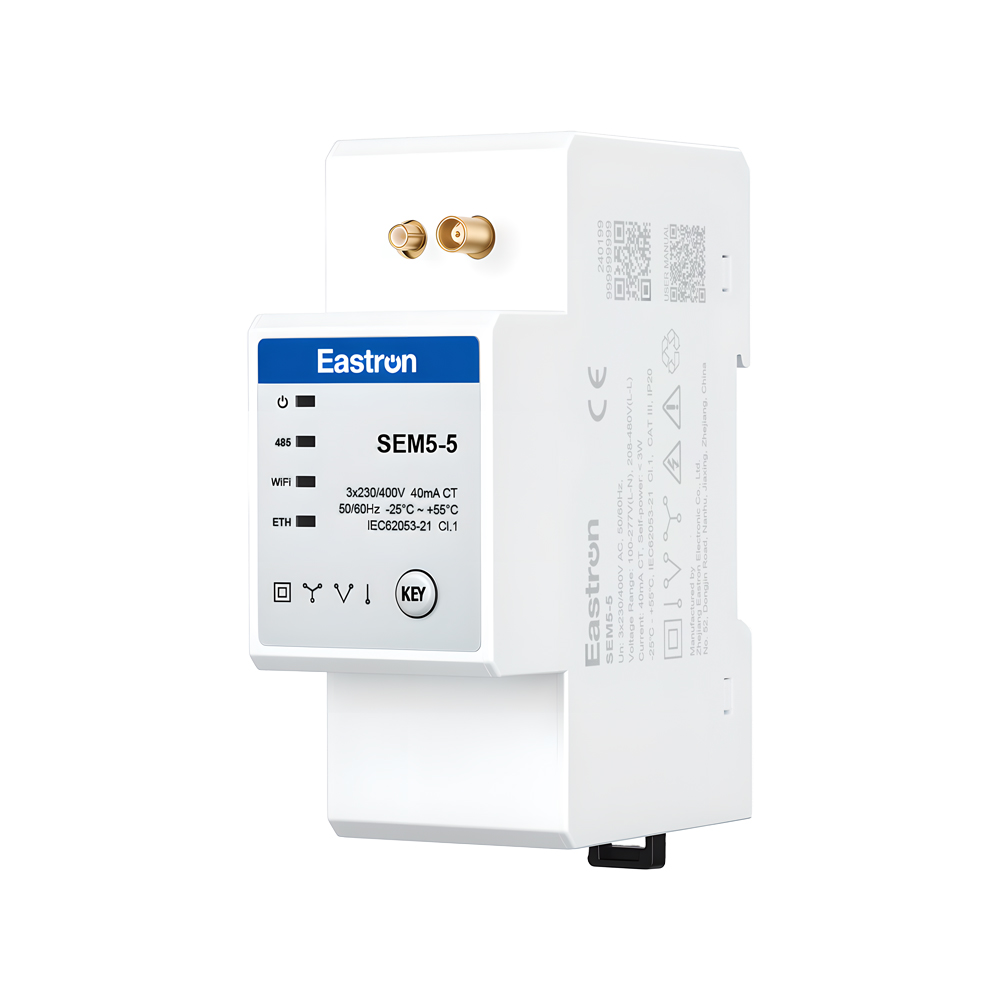
CT Operated Wireless Three Phase Energy Meter for PV Metering
May 30,2025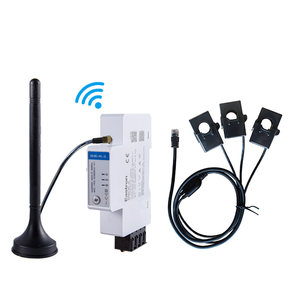
CT Type Three Phase Din Rail Wifi Energy Meter for PV Metering
May 30,2025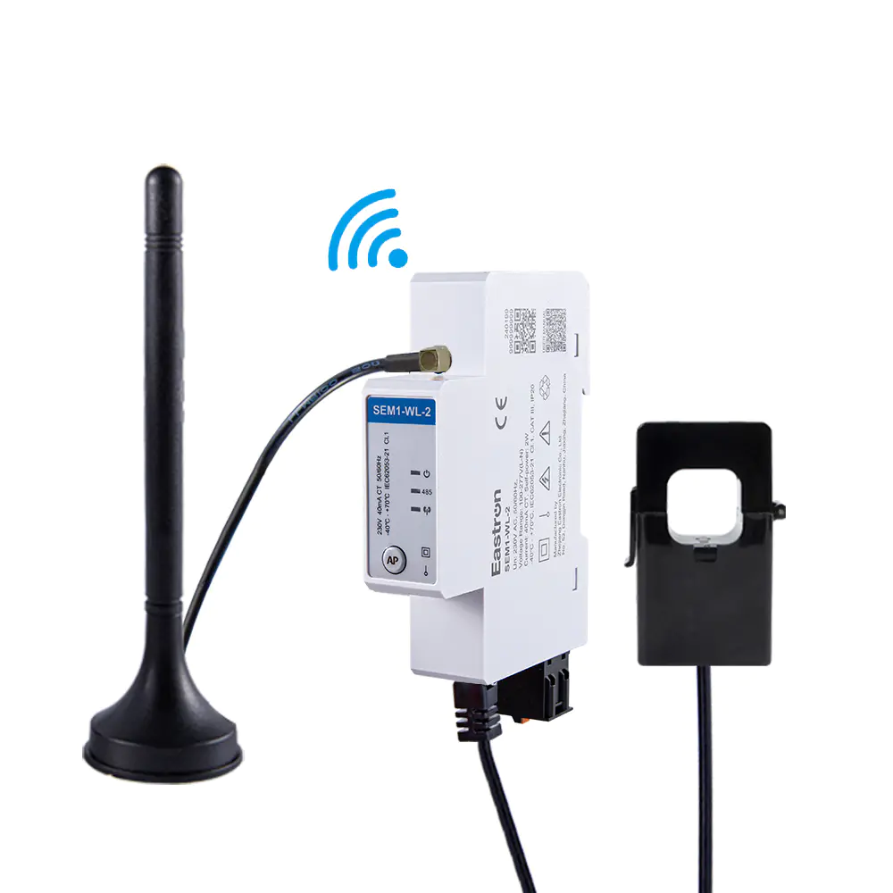
CT Connection Single Phase Din Rail Wifi Energy Meter for PV Metering
May 30,2025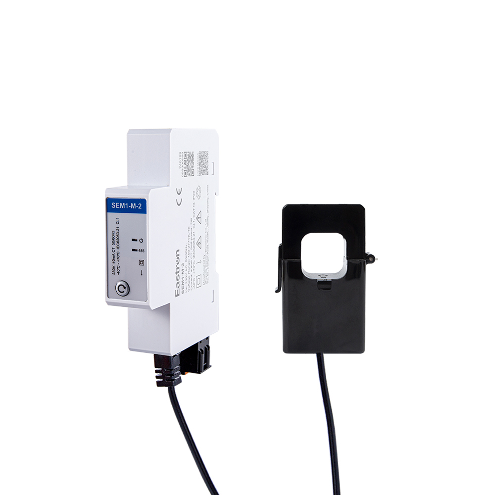
CT Type RS485 Modbus Single Phase Din Rail Energy Meter for PV Metering
May 30,2025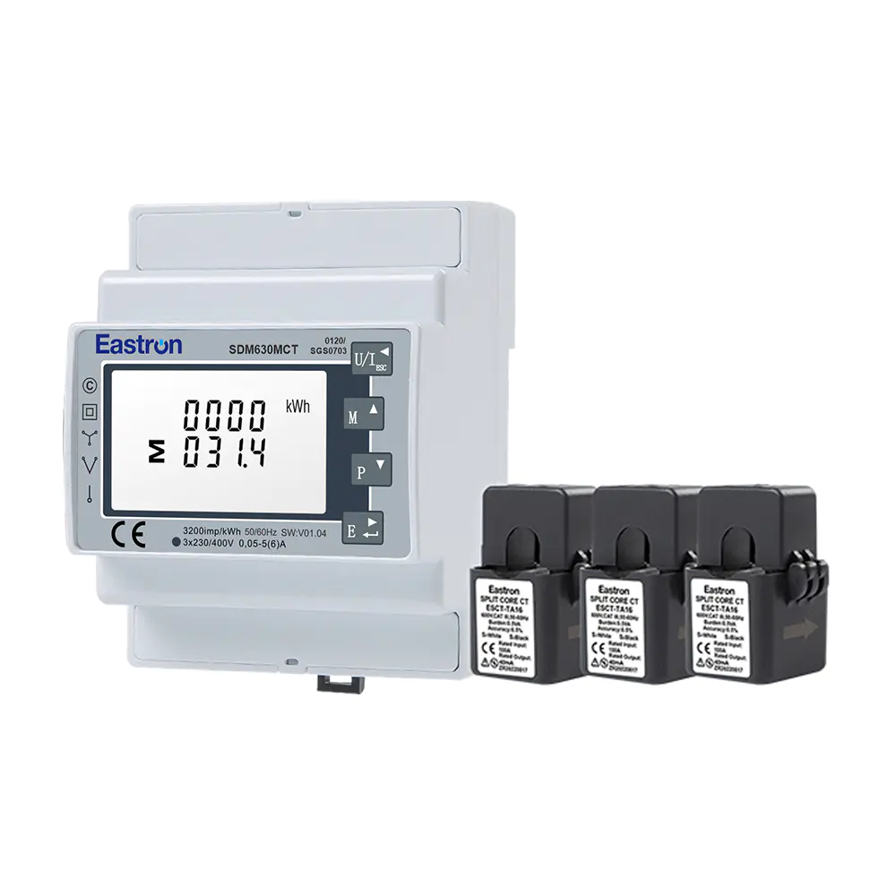
MID/UL CT Type Din Rail Three Phase Multi-function Energy Meter for EV Charging Metering
Nov 24,2022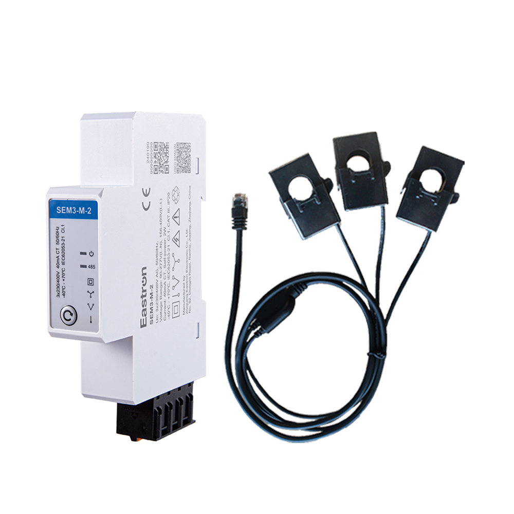
RS485 CT Connection Three Phase Din Rail Energy Meter for PV Metering
May 30,2025Content

Modern electrical installations increasingly require more than a simple indication of voltage or current. Building owners, industrial operators, renewable-energy developers, facility managers, and electrical contractors need reliable information about energy consumption, power quality, operating costs, and the performance of multiple power sources. A suitable meter must therefore combine measurement accuracy, communication capability, flexible wiring, dependable construction, and practical installation.
The SDM630MCT-2T is designed for these requirements. It is a DIN-rail-mounted, three-phase, current-transformer-operated energy meter with dual-tariff functionality, pulse outputs, RS485 Modbus communication, and MID certification. It can be used in 3P3W, 3P4W, and selected single-phase configurations, while its 1 A or 5 A CT input makes it suitable for installations where the measured current is too high for direct connection.
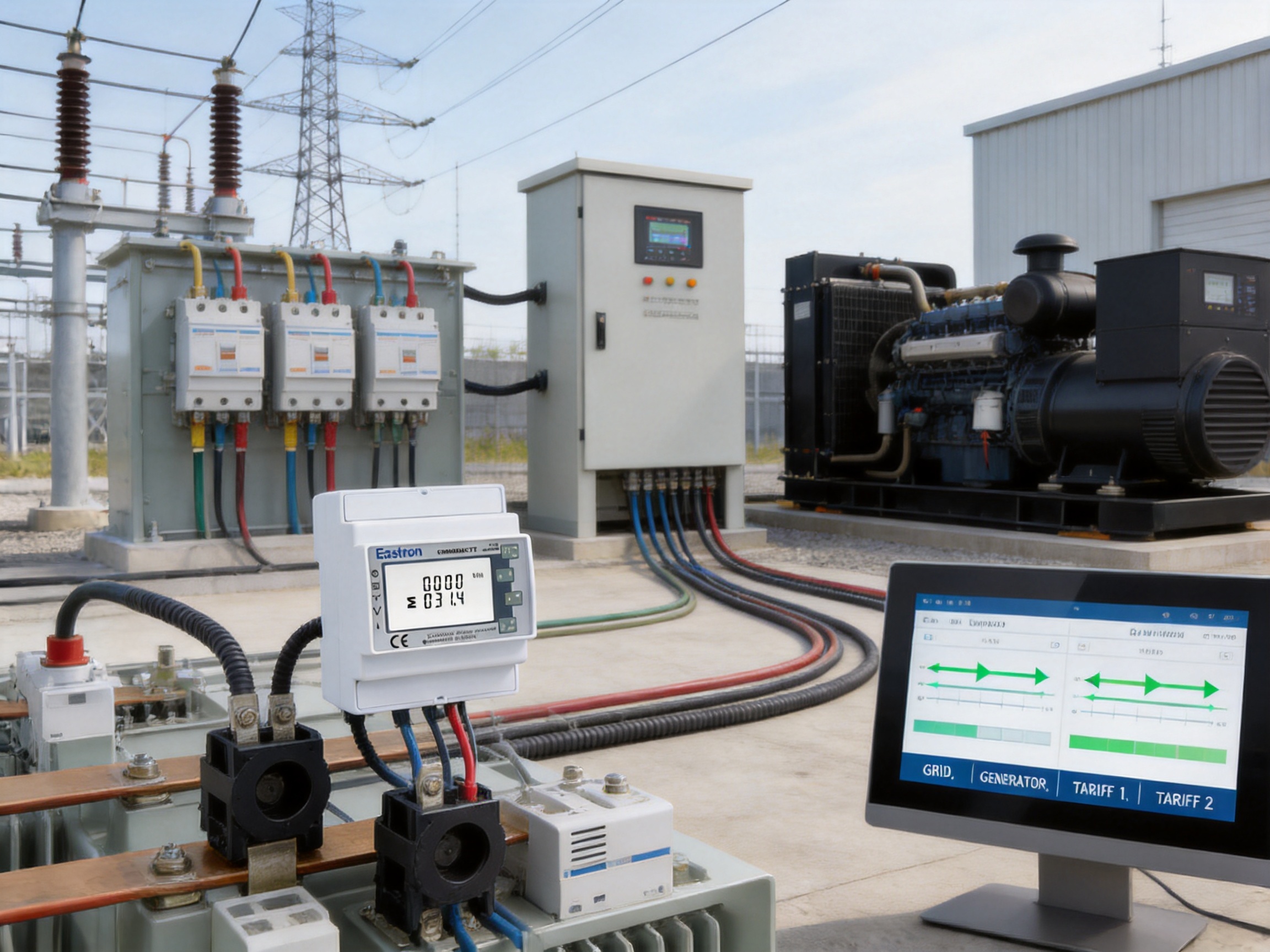
Its dual-source measurement function is particularly useful where energy may be supplied by both the utility grid and a generator. By supporting two tariffs or power-source channels, the meter can distinguish energy associated with different operating conditions. This provides a practical basis for energy allocation, sub-metering, cost analysis, and generator-versus-grid monitoring.
Manufactured by Eastron Electronic Co., Ltd., the meter reflects a product-development approach centered on electrical measurement, embedded software, communication technology, and compliance testing. The company operates professional laboratories for electromagnetic compatibility, low-voltage safety, accuracy, and environmental testing. These capabilities support the development of meters intended for demanding commercial, industrial, and energy-management applications.
The SDM630MCT-2T is a multifunction energy meter for three-phase AC systems. It measures electrical energy and a broad selection of instantaneous and calculated parameters, including active power, reactive power, apparent power, power factor, frequency, voltage, current, demand, active energy, and reactive energy.
Unlike a basic kWh counter, a multifunction meter provides a more complete picture of an electrical installation. A facility manager can use voltage and current readings to identify abnormal conditions, power values to understand loading, power factor to evaluate the efficiency of electrical consumption, and energy registers to support billing or internal cost allocation.
The meter uses external current transformers. The CTs reduce the primary current to a standardized secondary signal, normally 1 A or 5 A, which is then measured by the meter. The primary CT ratio can be configured over a broad range from 1 A to 9999 A. This allows one meter design to serve small commercial panels, larger distribution boards, generator outputs, and industrial feeder circuits.
Because the meter is CT-operated, the main circuit current does not pass directly through the meter body. This can simplify installation in high-current applications and reduce the physical size of the metering device. Proper CT selection, polarity, phase matching, and wiring remain essential for accurate measurement.
The four-module, 72 mm DIN-rail format provides a compact solution for switchboards and control cabinets. Compared with larger panel instruments or separate meters for each electrical parameter, a single multifunction unit can reduce panel space, wiring complexity, and commissioning time.
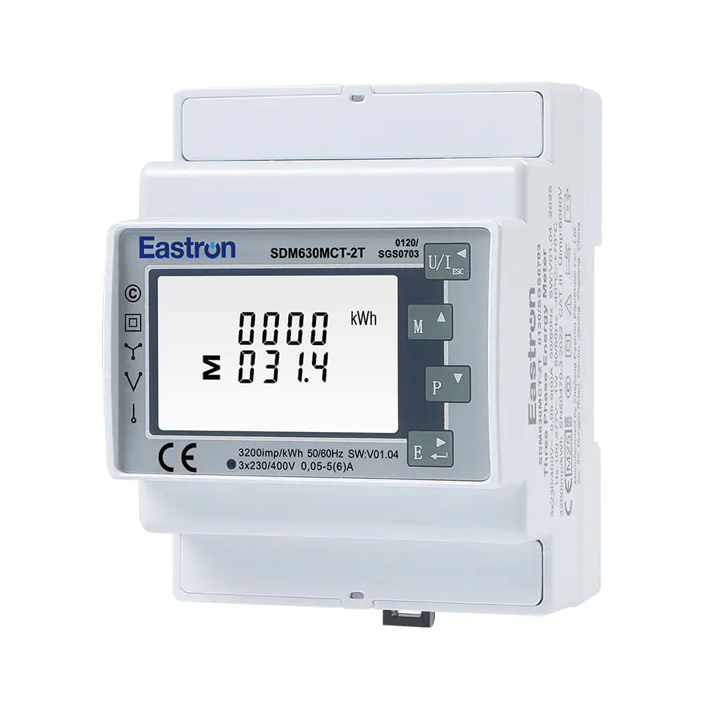
Dual Tariff RS485 Modbus CT Operated Din Rail Three Phase MID Energy Meter
One of the defining characteristics of the SDM630MCT-2T is its support for two tariffs associated with dual power sources. In practical terms, the meter can be used where electrical energy comes from two different sources, such as a utility grid and a standby generator.
Many facilities operate with more than one source of electricity. A commercial building may use the public grid during normal operation and transfer to a generator during an outage or peak-demand period. A factory may combine utility power with on-site generation. A telecommunications site may have grid and backup generation. A microgrid may use several supply paths, each requiring separate energy accounting.
When energy from these sources is measured without distinction, it can be difficult to determine how much energy was supplied by each source. Separate metering may require multiple devices, additional panel space, and more complicated data integration. The dual-tariff function provides an alternative by allowing the installation to identify energy associated with two defined operating channels.
This capability can support:
• Grid and generator energy comparison.
• Internal energy allocation between operating modes.
• Verification of generator runtime consumption.
• Analysis of energy purchased under different tariff conditions.
• Monitoring of normal and backup supply arrangements.
• Sub-metering for tenants, departments, production lines, or equipment groups.
• Data collection for energy-management systems.
Dual-tariff measurement is especially valuable when the cost or environmental impact of energy differs according to source or operating period. The meter can provide energy data that is easier to interpret than a single cumulative register covering all supply conditions.
The dual-source function does not eliminate the need for correct electrical system design. The installer must follow the wiring diagram, verify the source-selection arrangement, and ensure that the meter’s tariff terminals are connected to the intended control signals. The function should be commissioned together with the facility’s transfer-switching or source-control strategy.
The meter is intended for use with 3P3W and 3P4W systems. A 3P3W system is commonly used in three-phase installations without a neutral conductor, while a 3P4W system includes a neutral conductor and supports phase-to-neutral voltage measurement. The ability to work with both arrangements makes the device suitable for a wider selection of switchboards and distribution systems.
The product information also identifies support for 1P2W applications. This gives contractors additional flexibility when the same meter platform is required across different panels or when a project includes a mixture of three-phase and single-phase measurement points. The exact application should always be checked against the wiring instructions and the intended measurement configuration.
The rated voltage options include 230 V line-to-neutral and 120 V line-to-neutral. The operational voltage range is specified as 80% to 120% of the rated voltage. These values allow the meter to accommodate common low-voltage distribution environments, provided the installation remains within the specified electrical limits.
The CT input supports both 1 A and 5 A secondary currents. This is important because CT secondary standards vary between countries, industries, and existing installations. A facility may already use 5 A CTs in its switchgear, while a newer installation may select 1 A CTs to reduce secondary-circuit losses over longer cable runs.
The configured CT primary range of 1 A to 9999 A enables the meter to be matched to a wide range of current transformers. The selected ratio must correspond to the actual CT installed. Incorrect ratio programming can produce readings that are consistently too high or too low, even when the meter itself is functioning correctly.
The SDM630MCT-2T measures RMS values, including harmonics, on three-phase AC systems. RMS measurement is important because electrical loads are not always perfectly sinusoidal. Variable-speed drives, switch-mode power supplies, LED drivers, UPS systems, computers, and other electronic equipment can introduce waveform distortion.
By considering RMS values and harmonics, the meter provides a more representative indication of the electrical conditions experienced by equipment. This can help users identify overloaded circuits, unbalanced conditions, unexpected current demand, and changes in the behavior of nonlinear loads.
The primary measured and calculated parameters include:
• Voltage for each relevant phase and the associated system values.
• Current for the measured phase conductors.
• Active power, which represents useful real energy transfer.
• Reactive power, associated with inductive and capacitive behavior.
• Apparent power, combining active and reactive components.
• Power factor, indicating the relationship between active and apparent power.
• Frequency of the AC supply.
• Maximum demand or demand-related values.
• Active energy in both import and export directions.
• Reactive energy.
These measurements support both operational monitoring and long-term analysis. For example, a facility may use power factor data to evaluate compensation equipment, demand values to understand peak loading, and active-energy registers to compare consumption between production shifts.
Bi-directional measurement is another important feature. The meter can distinguish energy flowing into a load from energy flowing back toward the source. This is useful for installations with photovoltaic generation, battery storage, regenerative drives, combined heat and power, or other distributed-energy resources.
In a solar installation, for example, the meter can help identify imported energy when local generation is insufficient and exported energy when generation exceeds local demand. In a generator application, bi-directional measurement can support a clearer understanding of energy flow during synchronization, transfer, or unusual operating conditions.
Accuracy is central to any energy-metering application. The product specifications state voltage accuracy of ±0.5%, current accuracy of ±0.5%, frequency accuracy of ±0.2%, and power-factor accuracy of ±1%. Active, reactive, and apparent power are specified at ±1%.
For active energy, the meter is specified as Class 0.5S under IEC 62053-22 and Class 1.0 under IEC 62053-21. It is also identified with Class B and Class C performance under EN 50470-3:2022. Reactive energy is specified as Class 2 under IEC 62053-23.
These classifications help users evaluate whether the meter is appropriate for a particular project. A monitoring application may only require general operational information, while sub-billing, tenant allocation, cost recovery, or regulated metering may require more demanding performance. The applicable certification and installation requirements should be confirmed for the intended jurisdiction and use case.
The product has been assessed and certified as meeting the requirements of EU Directive 2014/32/EU. The supplied information identifies a traceable assessment number and also states that the meter is ETL listed by Intertek. These certifications and listings can simplify product evaluation for projects requiring documented compliance with recognized standards.
Certification is more than a label on the product. It reflects a process involving design review, testing, production controls, documentation, and traceability. For organizations purchasing meters for large projects, evidence of compliance can reduce approval time and provide greater confidence during audits or inspections.
The built-in RS485 interface uses Modbus RTU, one of the most widely adopted communication protocols in industrial automation and building-management systems. This allows the meter to exchange data with programmable logic controllers, energy-management platforms, supervisory control and data acquisition systems, data concentrators, gateways, and industrial computers.
Communication addresses from 1 to 247 are supported. Transmission speeds range from 1200 bps to 38400 bps, with selectable parity and stop-bit settings. The specified maximum transmission distance is up to 1000 meters under suitable installation conditions, and the response time is less than 100 milliseconds.
These settings make the product adaptable to both small and large RS485 networks. A single meter can be connected to a local controller, or multiple meters can be linked along a bus for centralized monitoring. Proper cable selection, shielding, grounding, termination, and network topology are important for reliable communication, especially over long distances or in electrically noisy environments.
Through Modbus, users can retrieve electrical parameters and energy registers without manually reading the display. Data can be logged at regular intervals, presented on dashboards, compared across departments, or used to generate alarms. A power-management system may trigger an alert if voltage leaves a defined range, current exceeds a threshold, power factor falls below a target, or energy demand reaches a preset level.
Communication also improves maintenance. A technician can review operating data remotely before visiting a site. Historical trends can reveal gradual changes that might not be visible during a brief inspection. Abnormal energy consumption may indicate equipment degradation, incorrect operating schedules, compressed-air leakage, refrigeration problems, or unauthorized loads.
The meter provides two pulse outputs in addition to its RS485 Modbus interface. Pulse outputs are useful for systems that count energy pulses through a building controller, programmable relay, remote terminal, or dedicated data logger.
Pulse-based integration is often selected when the receiving system does not support Modbus or when a simple electrical-energy signal is required. It can also provide an independent way to compare local data with values received through the communication interface during commissioning.
The two pulse outputs expand the possibilities for separating energy channels or connecting different monitoring functions. Their use depends on the configuration and the receiving equipment. The pulse constant, output characteristics, and wiring should be confirmed from the product documentation before commissioning.
RS485 and pulse outputs can be used together. For example, pulse outputs may feed a basic building-management input while Modbus provides detailed voltage, current, power, demand, and power-quality information to a central energy platform. This combination allows the same meter to serve both legacy and modern control systems.
At 72 mm wide, or four DIN modules, the meter is compact for the number of functions it provides. DIN-rail mounting allows it to be installed in standard distribution boards, metering compartments, control panels, generator panels, renewable-energy cabinets, and automation enclosures.
A compact form factor offers several practical advantages over larger or more fragmented metering arrangements. It can preserve cabinet space for protective devices and communication equipment. It can reduce the length of internal wiring. It can also make it easier to install multiple meters in a row for circuit-level sub-metering.
External CTs provide additional installation flexibility. The meter can be mounted near the control equipment while the CTs are installed around the relevant conductors. This arrangement is particularly convenient in retrofit projects where the main conductors cannot be disconnected or routed through a direct-connected meter.
Installation must be performed by qualified personnel. The CT secondary circuit should never be treated casually, and appropriate shorting or isolation procedures must be followed when a CT may become disconnected while primary current is flowing. Phase identification and polarity are also essential. Reversed CT polarity can produce incorrect power direction or energy readings.
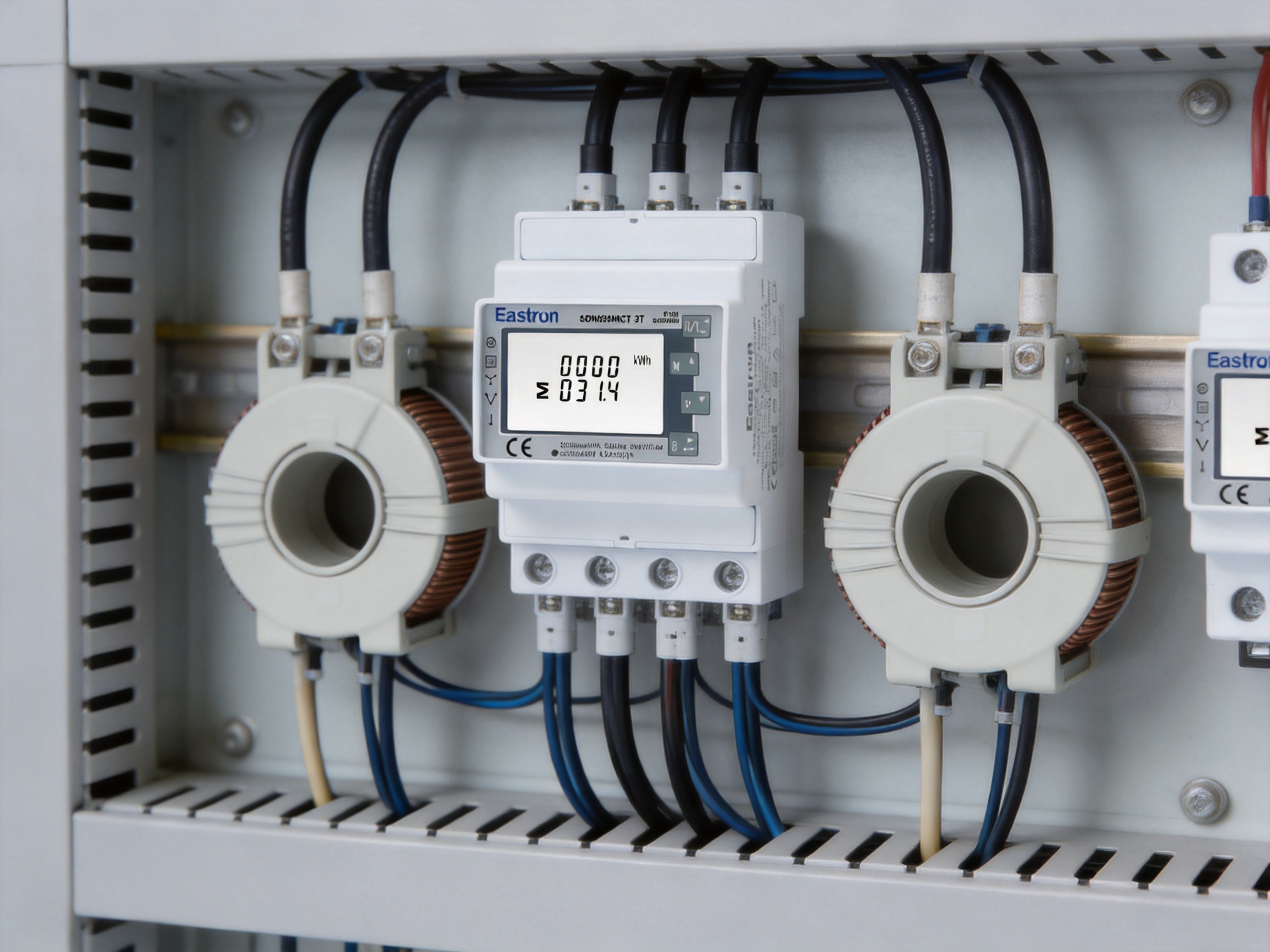
The SDM630MCT-2T offers several advantages over simple single-function meters and less flexible competing designs.
A basic kWh meter generally focuses on cumulative active energy. That may be sufficient for simple consumption recording, but it provides limited information for troubleshooting or optimization. The SDM630MCT-2T combines energy measurement with voltage, current, power, power factor, frequency, demand, and reactive-energy functions. This reduces the need for separate instruments.
Direct-connected meters are limited by their maximum current rating and may require large terminals or specialized construction. A CT-operated meter can be applied to higher-current circuits by selecting suitable external transformers. This makes the product more adaptable to industrial feeders, generator outputs, large commercial buildings, and distribution equipment.
Many conventional meters measure one energy channel only. The dual-tariff function allows the SDM630MCT-2T to support two defined source or tariff conditions. This can reduce the need for two independent meters where the electrical arrangement and project requirements permit combined measurement.
Some basic meters are designed mainly for one-way energy flow. Bi-directional measurement is more suitable for modern systems involving on-site generation, storage, or regenerative equipment. It provides a better foundation for understanding both imported and exported energy.
The standard model combines two pulse outputs with RS485 Modbus. Related versions in the same product family are available with M-Bus or LoRaWAN communication options. This family approach can help system integrators select a suitable communication method while maintaining a familiar meter format and measurement concept across different projects.
Documented accuracy classes and certification provide a stronger basis for project approval than an unclassified monitoring device. Where regulatory or contractual requirements apply, compliance documentation can be an important differentiator.
A four-module DIN-rail enclosure provides considerable functionality within a relatively small footprint. This is valuable in retrofit installations, where available panel space is often limited and expanding the enclosure can be costly.
The quality of an energy meter depends not only on its visible specifications but also on the engineering and manufacturing systems behind it. Eastron Electronic Co., Ltd. develops electricity meters, power analyzers, current sensors, communication modules, and energy-management products. This product concentration creates a technical foundation in electrical measurement, embedded electronics, communications, and power-system applications.
The company is headquartered in Jiaxing, China, in a region with strong electronics and electrical-manufacturing capabilities. Its development activities involve teams in China and the United Kingdom, supporting product innovation and international application knowledge. Cooperation with universities and technical institutions contributes to research, testing, and the adoption of newer technologies.
A significant strength is the company’s professional laboratory capability. The laboratory is equipped to perform EMC, low-voltage directive, accuracy, and environmental tests according to IEC, EN, GB, and UL requirements. In-house testing enables engineers to identify design issues earlier and to evaluate product behavior under controlled conditions before production release.
EMC testing is particularly important for meters with communication interfaces and pulse outputs. A meter installed in a switchboard may operate near contactors, variable-frequency drives, power converters, relays, and high-current conductors. Immunity testing helps evaluate whether the meter can continue operating when exposed to electrical disturbances, while emissions testing helps control the interference generated by the product itself.
Low-voltage safety testing evaluates aspects such as insulation, dielectric strength, clearances, creepage distances, and protection against hazardous electrical conditions. Accuracy testing verifies the measurement performance across defined voltage, current, power-factor, and frequency conditions. Environmental testing can assess the effects of temperature, humidity, vibration, and other conditions relevant to field service.
The company operates under an ISO 9001 quality-management system. A structured quality system supports controlled design changes, documented production procedures, supplier management, inspection, corrective action, and traceability. These processes are especially important for energy meters because measurement consistency must be maintained across large production quantities.
The company also reports patented technologies in software, embedded software, and hardware. For a connected meter, firmware is as important as the circuit design. Firmware manages measurement calculations, display functions, energy registers, communication behavior, tariff logic, pulse generation, and configuration settings. Software development and validation therefore form a major part of overall product reliability.
An advanced energy-meter manufacturing process typically begins with requirements definition. Engineers identify the intended electrical systems, accuracy targets, communication standards, mechanical constraints, certification requirements, and environmental conditions. These requirements are translated into hardware, firmware, enclosure, and testing specifications.
Electronic design follows with attention to measurement channels, isolation, power supply stability, current-transformer inputs, voltage sensing, signal conditioning, microcontroller functions, communication interfaces, and output circuits. Designs must balance accuracy, thermal performance, manufacturability, service life, and cost.
Prototype testing is used to verify the design under controlled conditions. Engineers can compare the meter with reference equipment, evaluate phase relationships, test different CT ratios, inspect communication reliability, and confirm behavior during voltage variation or abnormal conditions.
Production then depends on controlled assembly and inspection. Printed circuit boards require accurate component placement, solder-quality control, visual inspection, and functional testing. Firmware must be correctly loaded and associated with the appropriate product version. The enclosure, terminals, display, labels, and communication ports must be checked before final packaging.
Final testing may include power-up checks, display verification, input simulation, output verification, communication tests, accuracy tests, and safety inspections. Serial-number or batch-level records can support traceability and after-sales service. These controls help reduce the risk that a product with a hidden assembly or configuration issue will reach the customer.
The SDM630MCT platform includes versions with different communication technologies and functions. Besides the dual-tariff Modbus model, the product information identifies variants with standard Modbus, M-Bus EN 13757-3, and LoRaWAN communication.
This product-family strategy benefits engineering companies that manage several types of projects. A common measurement concept and enclosure style can reduce training requirements and simplify panel design. At the same time, communication options can be selected according to the building-management system, metering infrastructure, or wireless-network strategy.
Eastron’s stated focus on energy-measurement solutions also supports cooperation with distributors, system integrators, panel builders, and original-equipment manufacturers. Projects may require technical documentation, parameter configuration, communication mapping, batch supply, or application guidance. A manufacturer with expertise across meters, sensors, analyzers, gateways, and management systems can provide more coherent support than a supplier focused on a single isolated device.
Office buildings, retail centers, hotels, and mixed-use properties often need sub-metering for tenants, floors, HVAC systems, lighting, elevators, and common areas. The meter can provide energy data through Modbus while its CT configuration accommodates different feeder sizes.
Factories can use the device to monitor production lines, workshops, motors, compressors, furnaces, and auxiliary systems. Voltage, current, power factor, and demand information can help identify inefficient equipment or unexpected operating conditions.
The dual-source function is suitable for installations that alternate between utility power and generator power. It can support energy accounting for each source and help operators review generator-related consumption.
Bi-directional measurement supports systems with photovoltaic generation, battery storage, or other distributed-energy resources. Import and export registers can be integrated into an energy-management platform for performance analysis.
Data centers, telecommunications rooms, and critical infrastructure require continuous information about power conditions. The meter can provide data for branch-level monitoring, capacity planning, and alarm generation when integrated with a suitable supervisory system.
Energy contractors and service providers can use the meter in projects involving internal allocation, tenant billing, performance verification, or energy-saving programs. The applicable certification and local regulatory requirements should be reviewed before using any meter for legally regulated billing.
Successful metering begins with selecting the correct electrical configuration. The installer should identify whether the system is 3P3W, 3P4W, or another supported arrangement. The nominal voltage, frequency, phase sequence, CT secondary current, CT primary ratio, and power-source arrangement should be recorded before wiring.
CTs must be selected according to the expected primary current and the required accuracy. A CT that is too large for the normal operating current may provide poor resolution at low load, while a CT that is too small may saturate during high current. The CT class, burden, insulation level, window size, and installation method should match the application.
Each CT must be associated with the correct phase voltage and current input. Phase mismatch can cause incorrect power readings even when the individual current and voltage values appear reasonable. CT polarity also affects the direction of active power and energy. The primary and secondary markings should be followed carefully.
The CT secondary circuit should be handled according to established electrical safety procedures. If the primary conductor is energized, opening a CT secondary circuit can create a dangerous high voltage. Appropriate shorting terminals, test blocks, or approved isolation methods should be used when required.
The meter’s auxiliary supply must be connected within the specified range and according to the relevant wiring diagram. The device requires auxiliary power to operate. Power-supply selection, protective devices, conductor sizing, and isolation should comply with local electrical regulations.
For RS485 communication, installers should establish a clear bus topology and avoid unnecessary star connections. Shielded twisted-pair cable is often preferred in industrial environments. Termination and biasing should be considered according to the number of devices and the design of the connected master. The communication address, baud rate, parity, and stop bits must be consistent with the host system.
Commissioning should include a comparison with a trusted reference or a known load. The installer should verify voltage, current, active power, power factor, frequency, energy direction, tariff behavior, pulse outputs, and Modbus registers. A documented commissioning record can help identify wiring errors and provide a baseline for future maintenance.
| Category | Specification |
|---|---|
| Measurement system | RMS measurement including harmonics on three-phase AC systems |
| Supported wiring | 3P3W, 3P4W, and 1P2W applications as specified |
| Current input | External CT, 1 A or 5 A secondary |
| CT primary range | 1 A to 9999 A |
| Minimum current | 0.05 A |
| Starting current | 5 mA |
| Rated voltage | 230 V L-N or 120 V L-N |
| Operating voltage | 80% to 120% of rated voltage |
| Voltage accuracy | ±0.5% |
| Current accuracy | ±0.5% |
| Frequency accuracy | ±0.2% |
| Power-factor accuracy | ±1% |
| Active, reactive, and apparent power | ±1% |
| Active-energy accuracy | Class 0.5S IEC 62053-22; Class 1.0 IEC 62053-21; Class B and C EN 50470-3:2022 |
| Reactive-energy accuracy | Class 2 IEC 62053-23 |
| Outputs | Two pulse outputs and RS485 Modbus |
| Communication address | 1 to 247 |
| RS485 transmission distance | Up to 1000 m under suitable conditions |
| RS485 transmission speed | 1200 bps to 38400 bps |
| Parity | None, odd, or even |
| Stop bits | One or two |
| Response time | Less than 100 ms |
| Mounting | DIN rail |
| Width | Four modules, 72 mm |
| Tariff function | Two tariffs or dual power-source measurement |
For facility owners, the main benefit is visibility. Energy that was previously represented by a single monthly bill or a basic cumulative register can be divided into measurable operating categories. Owners can compare grid consumption with generator consumption, review energy use by tenant, and identify demand patterns over time.
The meter can also support more informed capital decisions. If power-factor measurements show persistent reactive demand, the owner may evaluate compensation equipment. If demand readings reveal high peaks, load scheduling or peak-shaving strategies may be considered. If current levels are consistently low on a feeder, the installation may have opportunities for circuit consolidation or equipment optimization.
Remote data access reduces dependence on manual readings. When the meter is connected to a suitable software platform, operators can view trends, export reports, and configure alarms. This is valuable for facilities with multiple buildings or geographically distributed assets.
Accurate records can also improve accountability. Departments or tenants can be charged according to measured consumption rather than estimated allocation. Maintenance teams can use historical readings to assess whether corrective work produced the expected improvement.
System integrators benefit from the combination of standard industrial communication and flexible electrical inputs. Modbus RTU is supported by a wide range of controllers and software platforms, reducing the need for proprietary interfaces. The 1 A and 5 A CT options make the meter suitable for various switchboard designs.
Panel builders can use the compact DIN-rail format to create standardized metering sections. The same family can be applied to multiple projects, with communication variants selected according to the customer’s infrastructure. This reduces design repetition and simplifies spare-parts planning.
The meter’s multifunction capability can reduce the number of panel instruments. Instead of installing separate voltage meters, ammeters, power meters, frequency meters, and energy counters, a single integrated device can provide the required information. Fewer devices may also mean fewer terminal connections and less internal wiring.
For contractors working on retrofit projects, CT operation can be easier to accommodate than direct connection. The CTs can be selected and installed around existing conductors, subject to safe working procedures and sufficient physical access.
Good energy management depends on consistent data. The meter’s accuracy specifications establish a measurement basis, but data quality also depends on correct installation, stable CT performance, appropriate configuration, and reliable communication.
Users should periodically review readings for plausibility. Sudden changes in power factor, energy direction, phase current, or voltage may indicate a real system event, but they may also indicate a loose connection, incorrect CT orientation, a changed CT ratio, or a communication-register error.
Long-term monitoring is most useful when data is collected at an appropriate interval. Short intervals can reveal demand peaks and switching events, while longer intervals are suitable for monthly energy comparisons. The monitoring platform should preserve timestamps, tariff status, source identity, and relevant meter configuration information.
When meters are replaced or reconfigured, the change should be documented. Energy registers, CT ratios, communication addresses, and tariff assignments should be recorded. This protects the continuity of historical analysis and helps prevent errors in billing or energy reporting.
Energy meters are often installed in systems where measured values influence financial decisions, operating procedures, or regulatory records. Certification provides an independent framework for evaluating performance and suitability.
The stated MID assessment demonstrates that the product has been evaluated against requirements associated with measuring instruments in the European market. The traceable assessment identification supports product documentation and inspection processes. ETL listing provides an additional recognized compliance reference for projects requiring North American certification pathways.
Users should distinguish between a meter used for general monitoring and one used for legally controlled billing. A certified product may be technically capable of a billing-related application, but the complete installation, sealing, configuration, verification, and local approval process may also be regulated.
Traceability is valuable throughout the product life cycle. It helps connect the meter to its test records, production batch, firmware version, and documentation. For large projects, traceability can simplify quality audits and support efficient investigation if a field issue occurs.
The meter is designed for fixed installation and continuous monitoring, but periodic inspection remains advisable. Maintenance personnel should check terminal tightness, CT wiring, communication status, enclosure condition, and the plausibility of measured values.
RS485 networks should be reviewed if communication faults appear. Common causes include duplicate addresses, mismatched baud rates, incorrect parity, reversed A and B conductors, missing termination, excessive network branches, electrical interference, and damaged cables.
Energy readings should be compared with expected load behavior. If all power values are negative when the installation should be importing energy, CT polarity or phase association may need to be checked. If one phase differs significantly from the others, the cause may be an actual load imbalance or an installation issue.
Where a generator or second source is monitored, tariff assignments should be checked after transfer-switch maintenance or control-system changes. A change in auxiliary contacts or source-selection logic could cause energy to be assigned to the wrong channel even though the electrical measurement remains functional.
Replacement planning should take into account the CT ratio, communication settings, tariff configuration, pulse-output requirements, and historical register treatment. Keeping this information in the maintenance record can reduce downtime during future service work.
It is a multifunction, three-phase, CT-operated energy meter for DIN-rail installation. It measures active and reactive energy as well as voltage, current, power, power factor, frequency, demand, and other electrical parameters.
Yes. Its two-tariff function supports dual power-source measurement, making it suitable for distinguishing energy associated with a utility grid and a generator when the installation is wired and configured correctly.
Yes. It accepts 1 A or 5 A CT secondary inputs. The CT primary ratio can be configured from 1 A to 9999 A, allowing the meter to be matched to a wide range of primary currents.
The product is specified for 3P3W and 3P4W systems and also supports 1P2W applications as identified in the product information. The installer should use the correct wiring diagram for the selected configuration.
Yes. The meter provides bi-directional measurement, which is useful for solar-generation systems, battery storage, regenerative loads, and other installations where energy can flow in both directions.
The SDM630MCT-2T includes an RS485 interface using Modbus RTU. It supports communication addresses from 1 to 247, transmission speeds from 1200 bps to 38400 bps, selectable parity, and one or two stop bits.
They can transmit energy pulses to compatible controllers, data loggers, building-management systems, or other equipment that accepts pulse inputs. Pulse outputs may be used alongside Modbus communication.
The meter is four DIN modules wide, corresponding to approximately 72 mm. It is intended for standard DIN-rail mounting in distribution and control panels.
The specifications identify Class 0.5S under IEC 62053-22, Class 1.0 under IEC 62053-21, and Class B and C under EN 50470-3:2022. The relevant class for a project should be confirmed according to the intended application and local requirements.
It has MID-related certification and recognized accuracy classifications, but whether it can be used for legal billing depends on the jurisdiction, installation method, verification process, sealing requirements, and applicable regulations. Project authorities should confirm the complete compliance requirement.
The rated voltage options include 230 V line-to-neutral and 120 V line-to-neutral. The specified operational range is 80% to 120% of the rated voltage.
The installer should verify the wiring system, phase sequence, CT ratio, CT polarity, source or tariff assignment, auxiliary supply, communication settings, pulse-output connections, and agreement between the meter readings and a trusted reference.
It combines energy measurement with multifunction electrical monitoring, dual-source capability, bi-directional measurement, CT flexibility, pulse outputs, RS485 Modbus, and a compact DIN-rail format. This provides more information and integration potential than a basic single-register energy counter.
The SDM630MCT-2T is a practical solution for installations that require accurate three-phase energy measurement, flexible CT operation, dual-source accounting, and digital communication. Its support for 3P3W and 3P4W systems, 1 A or 5 A CT inputs, bi-directional measurement, two pulse outputs, and RS485 Modbus makes it suitable for a broad range of commercial, industrial, infrastructure, and energy-management applications.
Its dual-tariff function provides a clear advantage in facilities that use both grid and generator power or need to separate energy according to operating conditions. Its measurement of voltage, current, power, demand, power factor, frequency, and energy supports more informed decisions than a basic kWh meter can provide.
The compact four-module DIN-rail housing helps conserve panel space, while the CT-operated design allows the meter to serve higher-current circuits without direct primary-current connection through the meter body. Recognized accuracy classifications, MID assessment, and ETL listing provide useful compliance references for projects requiring documented performance.
Behind the product is a manufacturer focused on electricity meters, power analyzers, sensors, communication modules, and energy-management solutions. Professional laboratory testing, ISO 9001 quality management, international engineering resources, embedded-software development, and experience with IEC, EN, GB, and UL requirements strengthen the product-development and manufacturing foundation.
For facility owners, the meter improves energy visibility. For integrators, it provides a standard Modbus interface and flexible measurement architecture. For panel builders, it combines multiple functions in a compact DIN-rail package. For operators of mixed-source systems, it provides a practical method of distinguishing energy from two supply conditions. These combined characteristics make it a strong choice for connected electrical measurement and modern energy-management projects.
IEC 62053-21, Electricity Metering Equipment: Particular Requirements for Static Meters for AC Active Energy.
IEC 62053-22, Electricity Metering Equipment: Particular Requirements for Static Meters for AC Active Energy, Classes 0.1S and 0.2S.
IEC 62053-23, Electricity Metering Equipment: Particular Requirements for Static Meters for Reactive Energy.
EN 50470-3:2022, Electricity Metering Equipment: Particular Requirements for Static Meters for AC Active Energy.
EN 13757-3, Communication Systems for Meters and Remote Reading of Meters: Dedicated Application Layer.
Directive 2014/32/EU of the European Parliament and of the Council on Measuring Instruments.
Modbus Application Protocol Specification and Serial Line Implementation Guide.
SDM630MCT-2T Product Information and Technical Specifications.
Eastron Electronic Co., Ltd. Quality, Manufacturing, and Company Information.
Your email address will not be published. Required fields are marked *

We develop and produce high performance electricity meters, power analyzers, current sensors, communication modules and management systems.
Address:NO. 52, Dongjin Road, Nanhu, Jiaxing, Zhejiang, China
Copyright @ Eastron Electronic Co., Ltd. All rights reserved
