

 English
 Español
 Deutsch
 中文简体


Product Consultation
Your email address will not be published. Required fields are marked *
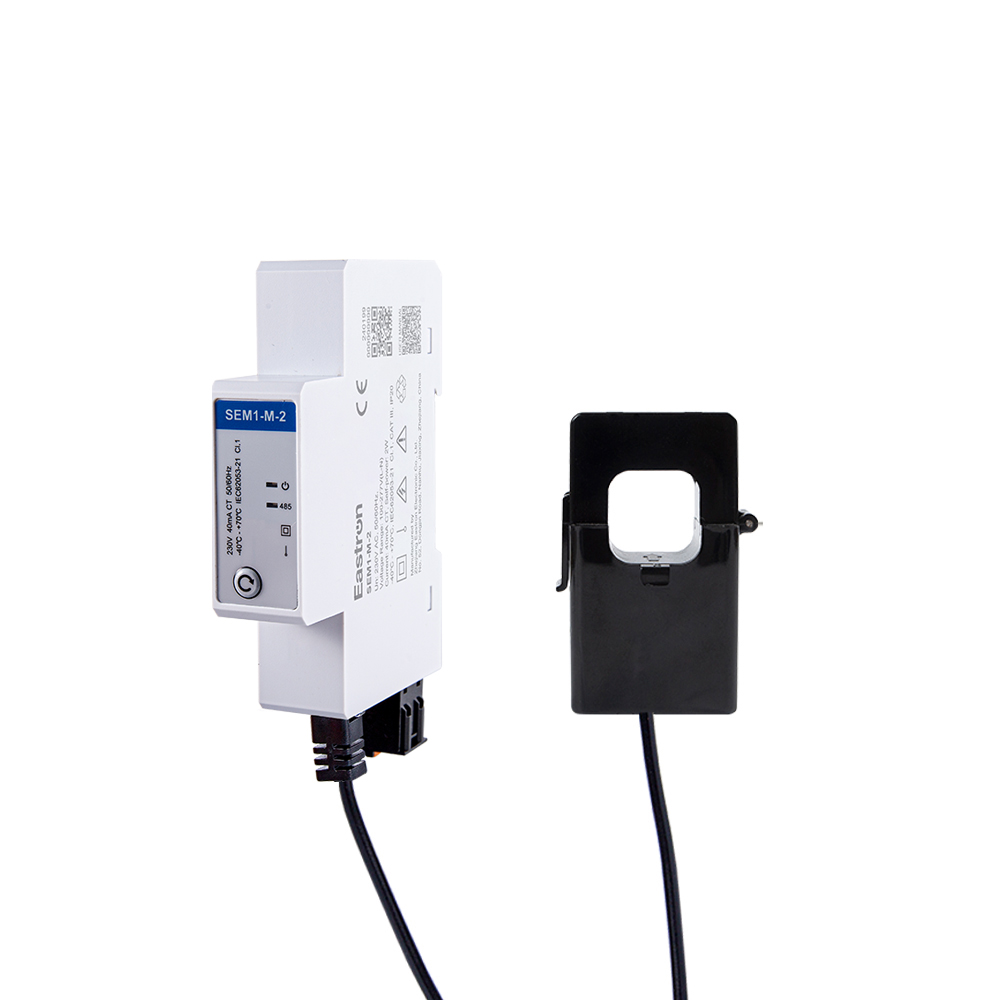
CT Type RS485 Modbus Single Phase Din Rail Energy Meter for PV Metering
May 30,2025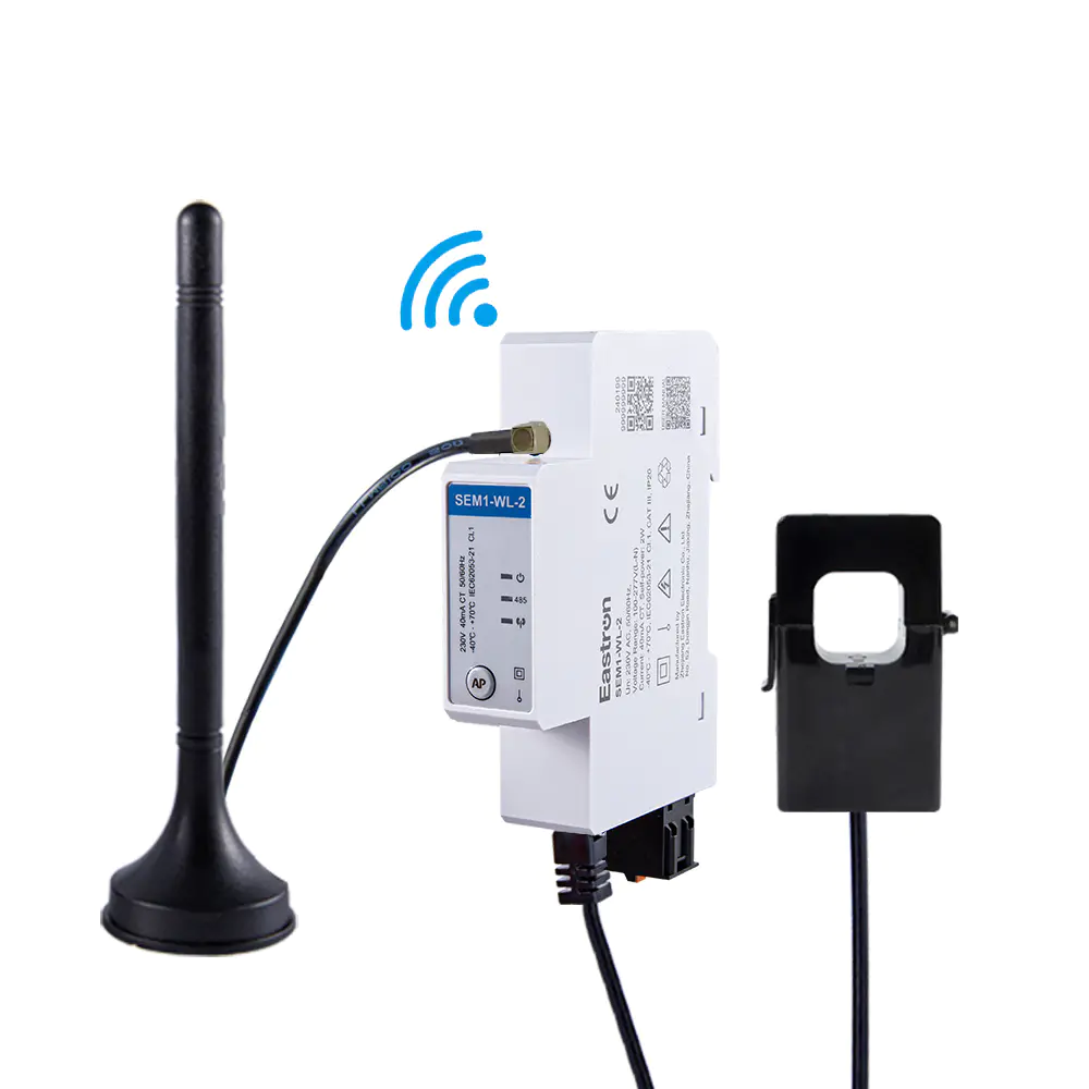
CT Connection Single Phase Din Rail Wifi Energy Meter for PV Metering
May 30,2025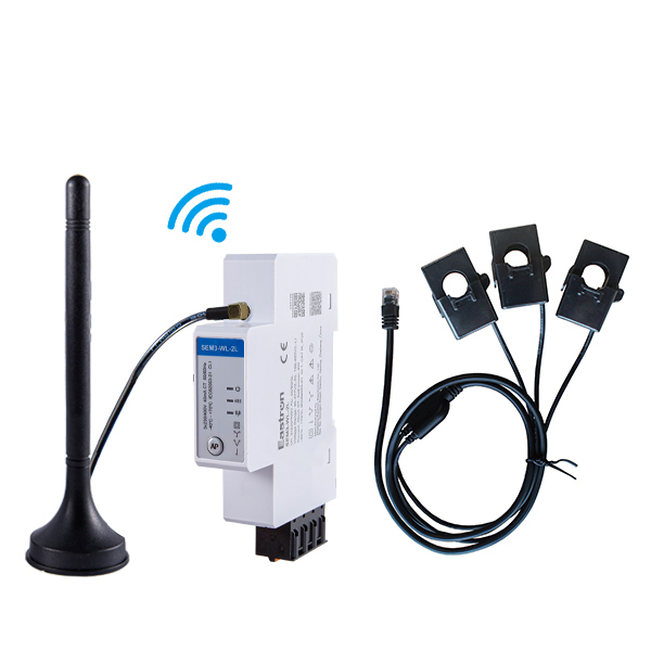
CT Type Three Phase Din Rail Wifi Energy Meter for PV Metering
May 30,2025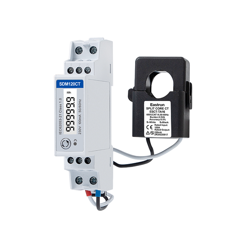
MID Certifed CT Operated Din Rail Single Phase Multi-function EV Meter for Load Balancing Solution
Oct 26,2026
CT Operated Wireless Three Phase Energy Meter for PV Metering
May 30,2025
MID/UL CT Type Din Rail Three Phase Multi-function Energy Meter for EV Charging Metering
Nov 24,2022Content
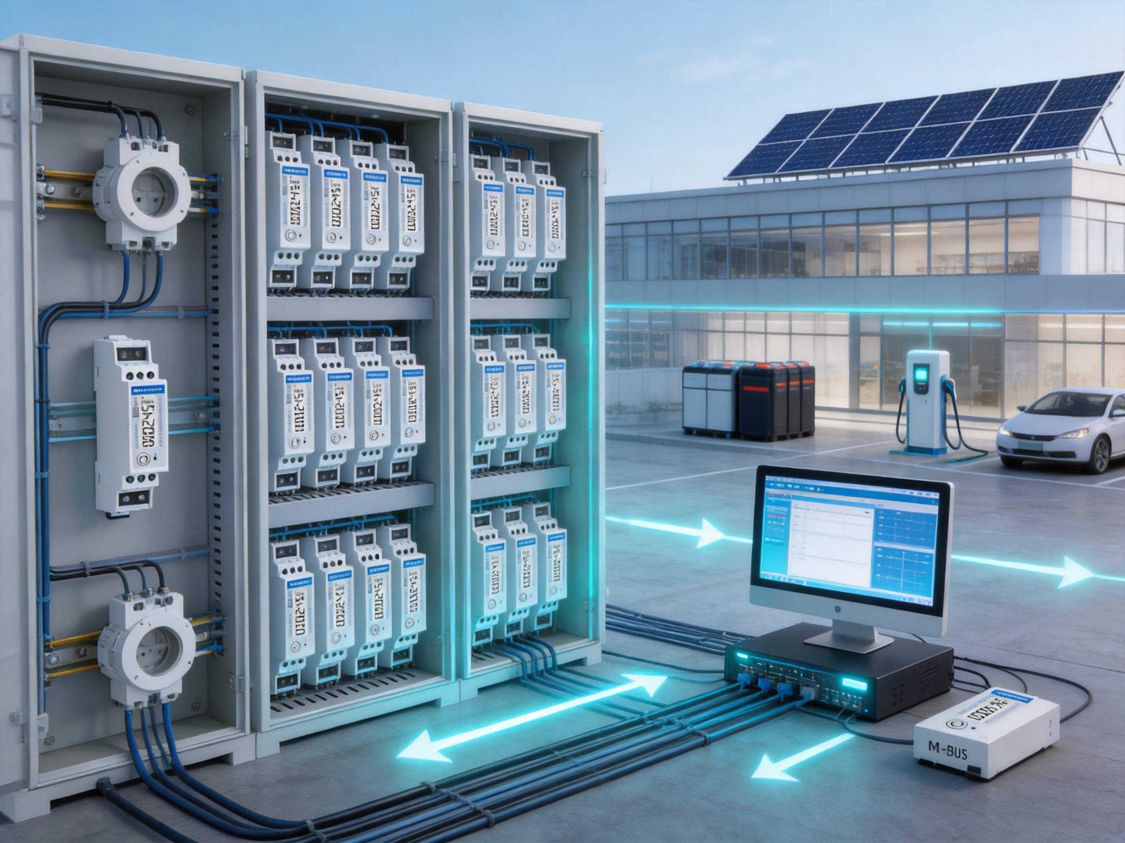
Modern electrical installations require more than a simple total-energy reading. Facility operators, building managers, equipment manufacturers, landlords, and system integrators increasingly need to understand how electricity is being used, when consumption occurs, and how electrical loads behave over time. A compact meter must therefore combine accurate measurement, practical installation, communication capability, and dependable long-term operation.
The SDM120CTMB is a single-phase, multi-function energy meter designed for applications in which current transformers are preferred or required. It is a 1P2W meter for single-phase AC systems, with a rated voltage of 230 V and a configurable CT primary range from 1 A to 9999 A. Its CT-operated architecture allows the meter to monitor current without routing the full load current directly through the meter body. This makes it suitable for a broad range of residential, commercial, industrial, and utility-related monitoring applications.
Installed on a DIN rail and occupying only one 18 mm module, the meter is designed to provide extensive measurement functions in a very small enclosure. It can measure active energy, reactive energy, voltage, current, power, power factor, frequency, and demand-related values. Depending on the selected communication version, the meter can also provide pulse outputs, Modbus communication, or M-Bus communication.
This combination of compact construction, CT flexibility, bidirectional measurement, communication support, and MID approval gives the product a strong position among single-phase energy meters intended for sub-metering and energy management systems.
The meter is a CT-type DIN rail single-phase multi-function energy meter for a 1P2W electrical system. In a typical installation, the meter measures the line voltage directly while receiving the load-current signal from a current transformer. The CT separates the measurement circuit from the higher-current conductor and enables the same meter design to be used with different current capacities.
The product is identified as the SDM120CTMB in its M-Bus configuration. This version provides two pulse outputs and M-Bus communication according to EN 13757-3. The wider SDM120CT product family also includes versions with pulse output only and versions with pulse output plus RS485 Modbus communication. This family approach gives panel builders and energy-management designers a practical way to select the required interface while retaining a consistent meter format.
The main functions include:
By combining these functions in one compact instrument, the meter can reduce the need for separate indicating instruments, pulse converters, and communication devices. It is particularly useful where the available panel space is limited but the installation still requires detailed electrical data.
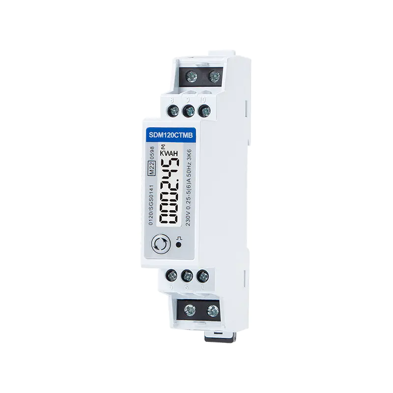
Mbus CT Type Din Rail Single Phase Multi-function Energy Meter
Direct-connected meters are appropriate for many low-current applications, but they are not always the best solution for circuits carrying higher current. A CT-operated meter uses a current transformer to reduce the primary current to a standardized secondary signal, commonly 1 A or 5 A. The meter then calculates the primary current and corresponding power and energy values according to the configured CT ratio.
The SDM120CTMB supports CT primary values from 1 A to 9999 A and CT secondary values of 1 A or 5 A. This range gives system designers considerable flexibility. A small installation may use a low-current CT, while a larger feeder can use a CT with a much higher primary rating without changing the basic meter format.
CT operation provides several practical advantages:
Correct CT selection and installation remain essential. The CT primary rating should be suitable for the monitored circuit, while the secondary rating must match the meter configuration. The CT polarity must also be observed, especially when measuring bidirectional power or export energy. A reversed CT can cause incorrect power direction or inaccurate energy accumulation.
Because the meter supports bidirectional measurement, it can be applied to installations where energy flows in both directions. Examples include solar photovoltaic systems, battery storage systems, microgrids, and facilities that both consume and generate electricity. Import and export energy can be monitored without installing separate meters for each direction.
A principal advantage of a multi-function meter is that it provides context around energy consumption. A basic kWh meter shows accumulated energy, but it cannot by itself explain why consumption has changed. The SDM120CTMB provides a broader group of electrical parameters that can assist with operation, maintenance, load analysis, and system optimization.
Active energy is the energy used to perform useful work and is commonly expressed in kilowatt-hours. The meter measures active energy in both directions, allowing users to distinguish between imported energy and exported energy where the application requires it. Active-energy accuracy is specified according to IEC 62053-21 Class 1.0 and EN 50470-1/3 Class B.
Class 1.0 and Class B performance makes the meter appropriate for many sub-metering, allocation, monitoring, and energy-management duties. The exact suitability for a regulated billing application depends on the installation, local regulations, certification scope, and the way the meter is commissioned.
Reactive energy is associated with inductive and capacitive loads. Motors, transformers, fluorescent lighting systems, power supplies, and other electrical equipment can contribute reactive demand. Monitoring reactive energy can help users understand power-factor behavior and identify conditions that may increase losses or utility charges.
The meter provides reactive-energy measurement to IEC 62053-23 Class 2 and IEC 61557-12 Class 2 performance specifications. This makes it useful for diagnostic monitoring and energy-management systems that need more information than active-energy data alone.
Voltage and current readings help users verify whether an electrical circuit is operating within its expected range. A change in current may indicate altered equipment loading, a process change, or a developing fault. A change in voltage can affect motors, heating systems, power supplies, and other connected loads.
The specified accuracy is 0.5% of range maximum for both current and voltage. Current measurement is based on the selected CT, while voltage is measured on the single-phase supply. These readings can be shown locally on the LCD or integrated into a supervisory energy-management platform through the communication interface.
Power measurement provides an immediate view of the rate at which a load is consuming or delivering electrical energy. It can be used to identify peak loading, compare equipment performance, and support capacity planning. The meter specifies power accuracy at 1% of range maximum.
Power factor indicates how effectively current is being converted into useful power in an AC system. A low power factor may cause higher current for the same useful power, increasing conductor losses and reducing available system capacity. The meter measures power factor with an accuracy of 1% of unity, or 0.01.
Frequency measurement helps verify the quality and stability of the supply. The meter specifies frequency accuracy at 0.2% of mid-frequency. Frequency information can be useful in generator systems, isolated networks, industrial facilities, and installations where supply conditions must be monitored continuously.
Demand data can help users understand the highest or changing electrical loading over a defined period. This is valuable for tariff analysis, equipment scheduling, transformer utilization, and load management. By combining energy, power, and demand information, operators can make better decisions about when to run high-consumption equipment or where to reduce simultaneous loads.
| Measured or Supported Function | Application Value |
|---|---|
| Active energy | Consumption and generation accounting |
| Reactive energy | Power-factor and reactive-load analysis |
| Voltage | Supply verification and voltage monitoring |
| Current | Load monitoring and circuit utilization analysis |
| Power | Instantaneous load assessment |
| Power factor | Efficiency and electrical-load evaluation |
| Frequency | Supply stability monitoring |
| Demand-related values | Peak-load analysis and energy planning |
| Bidirectional energy | Import and export monitoring |
Space is a major consideration in modern distribution boards, control panels, metering cabinets, and retrofit projects. The SDM120CTMB is designed to occupy one 18 mm DIN rail module. This narrow format allows multiple meters to be installed side by side, making it possible to monitor several circuits without requiring a large enclosure.
A compact meter can reduce panel size, simplify wiring routes, and leave more room for protective devices, communication equipment, and control components. It is also suitable for applications in which the meter must be added to an existing panel without extensive modification.
DIN rail installation provides a standardized mechanical mounting method. Once the rail is prepared and the wiring is correctly identified, the meter can be positioned consistently with other modular devices. This supports efficient production-panel assembly and helps installers maintain a clear, organized layout.
The compact enclosure does not mean that the meter is limited to one simple reading. The front-mounted LCD provides local access to measurement data, while the communication and pulse interfaces allow the information to be transferred to a larger monitoring system. This combination supports both stand-alone and networked operation.
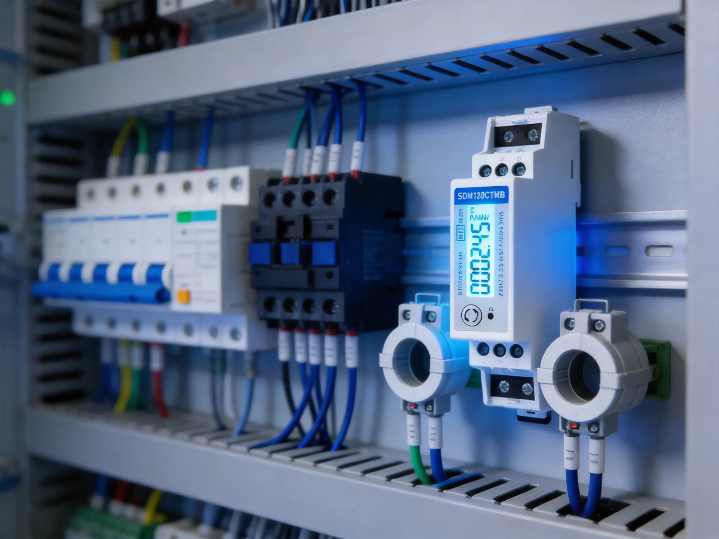
The backlit LCD improves visibility in distribution boards, plant rooms, equipment cabinets, and other areas where lighting may be limited. A local display is valuable during commissioning because installers can check basic readings without connecting a laptop or accessing the central energy-management system.
Local visibility also supports maintenance. A technician can inspect voltage, current, power, energy, or power factor at the meter location and compare the result with the expected operating condition. This can shorten troubleshooting time and provide an immediate indication of whether a circuit is energized and behaving normally.
In applications where the meter is connected to a remote system, the LCD remains useful as a verification tool. It allows the user to compare a locally displayed value with the value received by the monitoring software. This can help identify incorrect CT ratios, wiring errors, communication configuration problems, or unexpected scaling factors.
Pulse outputs offer a simple and widely supported method for transferring energy data to external equipment. A pulse can represent a defined amount of imported or exported energy. Building controllers, data loggers, programmable controllers, and energy-management systems can count these pulses and calculate consumption over time.
The meter provides two pulse outputs for import and export energy. This is particularly useful for installations that need to distinguish between energy received from the grid and energy delivered to the grid. Pulse interfaces can also be used when the control system does not support a digital meter protocol or when a simple independent verification channel is preferred.
Pulse outputs are often valued for their straightforward architecture. They can be used with existing pulse-counting inputs and do not require a complex software driver. They also provide a practical backup or comparison channel alongside M-Bus communication.
When planning a pulse-based system, the integrator should confirm the pulse constant, input requirements of the receiving device, cable length, signal type, and required isolation. The pulse-counting system should also be configured to distinguish between import and export channels where both are being monitored.
The SDM120CTMB supports M-Bus communication according to EN 13757-3. M-Bus is widely used in utility and building-metering networks because it is designed for communication with meters and other distributed measuring devices.
An M-Bus network can connect multiple meters to a central master, gateway, or data-collection system. Rather than requiring a separate local display for every circuit, facility operators can collect readings in a central software platform. This supports dashboards, historical records, alarms, reports, and allocation calculations.
The meter provides a communication address range from 1 to 250. Its specified transmission distance is up to 1000 m, subject to the cable type, network design, load conditions, topology, and installation environment. Transmission speeds range from 300 bps to 9600 bps. Parity can be configured as none, odd, or even, and one or two stop bits are supported. The specified response time is less than 100 ms.
| M-Bus Parameter | Specification |
|---|---|
| Communication standard | EN 13757-3 |
| Address range | 1–250 |
| Maximum stated transmission distance | 1000 m |
| Transmission speed | 300 bps–9600 bps |
| Parity | None, odd, or even |
| Stop bits | 1 or 2 |
| Response time | Less than 100 ms |
M-Bus capability gives the product an advantage over basic meters that only provide a local display. It allows the meter to become part of a coordinated energy-monitoring architecture. In a building with many tenants or separately monitored circuits, data can be collected centrally and used for consumption analysis, internal allocation, maintenance planning, and energy-efficiency programs.
The product’s advantages are most apparent when it is compared with simpler meter types. A basic direct-connected kWh meter may provide an economical solution for a single low-current circuit, but it may not offer CT flexibility, reactive-energy data, power-factor information, bidirectional measurement, or network communication.
By contrast, the SDM120CTMB is intended for more demanding monitoring requirements. Its CT input allows it to measure circuits with a wide range of primary currents. Its multi-function measurement capability gives users more information about circuit performance. Its two pulse outputs and M-Bus interface support integration with control and data-collection systems. Its one-module width helps retain a compact installation footprint.
Compared with a larger multifunction power analyzer, the product offers a simpler and more space-efficient option for single-phase circuits. A high-end power analyzer may be appropriate where advanced waveform analysis, harmonics, transient capture, or extensive power-quality functions are required. However, those additional capabilities may involve higher cost, larger dimensions, and greater configuration complexity. For routine energy measurement and electrical-parameter monitoring, a focused single-phase meter can be more practical.
Compared with meters that only measure consumption in one direction, bidirectional operation makes the product more suitable for distributed-generation and storage applications. Users can monitor both energy imported from the supply and energy exported from local generation.
| Feature | Basic Direct-Connected Meter | CT-Type Multi-Function Meter |
|---|---|---|
| Current measurement method | Direct connection | External current transformer |
| Current range flexibility | Usually limited by direct input rating | Broad range through CT selection |
| Active energy | Commonly available | Available with import and export measurement |
| Reactive energy | May not be available | Available |
| Voltage, current, power, and PF | Limited or unavailable | Available |
| Communication | May be unavailable | M-Bus and pulse outputs |
| Panel footprint | Varies | One 18 mm module |
| Typical use | Simple local energy indication | Sub-metering and connected energy management |
Measurement accuracy is one of the most important factors when selecting an energy meter. The SDM120CTMB specifications identify performance classes and standards for active energy, reactive energy, voltage, current, frequency, power, and power factor.
Active-energy measurement is specified to IEC 62053-21 Class 1.0 and EN 50470-1/3 Class B. Reactive-energy measurement is specified to IEC 62053-23 Class 2 and IEC 61557-12 Class 2. These references provide a structured basis for evaluating meter performance rather than relying only on general marketing descriptions.
Accuracy is affected by the complete installation, not only the meter electronics. The selected CT, CT accuracy class, burden, wiring, polarity, operating temperature, supply quality, and commissioning settings can all influence the final result. For this reason, the meter should be installed according to the technical instructions, with particular attention to CT ratio configuration and conductor routing.
MID approval is another important product strength. MID is a European measurement-instrument framework that defines requirements for certain regulated measuring instruments. The presence of MID approval can support projects that require an approved meter for specific measurement or allocation purposes. Project engineers should always verify that the exact model, application, installation method, and local legal requirements match the intended use.
The meter can be used to monitor individual apartments, outbuildings, heat pumps, electric vehicle charging circuits, or other major loads. Its compact size is useful in residential distribution boards where enclosure space is limited. M-Bus communication can transfer readings to a central building-management or billing platform.
Offices, retail premises, hotels, schools, and mixed-use buildings often need to measure different areas or systems separately. The meter can monitor lighting distribution boards, tenant circuits, HVAC equipment, kitchens, server-room supplies, and other single-phase loads. Centralized communication enables facility managers to compare consumption across zones and identify abnormal patterns.
Many industrial machines include single-phase auxiliary circuits, control panels, pumps, fans, heaters, and service outlets. The meter can provide a dedicated view of these circuits without occupying much panel space. Voltage, current, power, and power-factor data can help maintenance teams understand operating conditions.
Bidirectional measurement makes the meter suitable for circuits in which electricity can flow toward or away from the monitored point. It can be used to observe energy imported from the grid and energy exported from photovoltaic generation or battery equipment. Correct CT orientation and system configuration are especially important in these applications.
Energy-service companies and system integrators can use networked meters to collect data from multiple end points. The compact format supports high-density installations, while M-Bus communication provides a standardized method for connecting the devices to a master or gateway. This can support tenant allocation, operational reporting, and energy-performance verification.
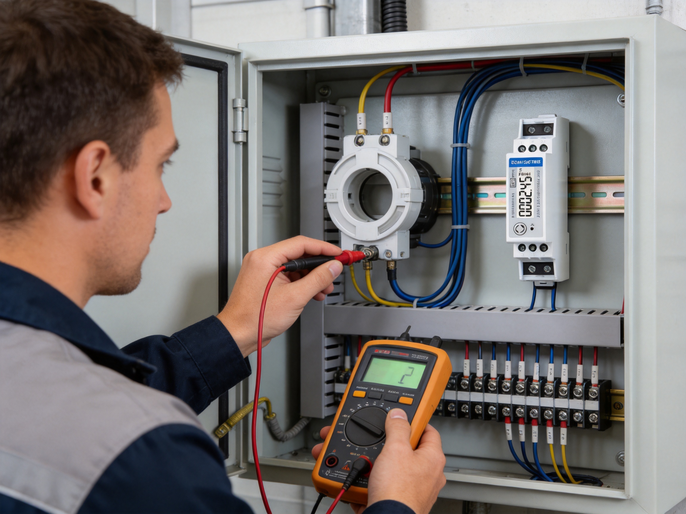
A reliable energy meter depends not only on its published specifications but also on the manufacturing systems used to produce and verify it. The manufacturer has developed capabilities in electricity meters, power analyzers, current sensors, communication modules, and energy-management systems. This product focus supports knowledge across measurement electronics, embedded software, communications, enclosure design, and production testing.
The company operates professional laboratory capabilities for electromagnetic compatibility, low-voltage safety, accuracy, and environmental testing. These testing areas are important because a meter must perform reliably in real electrical environments rather than only under ideal laboratory conditions.
Accuracy testing verifies whether the meter measures voltage, current, power, energy, frequency, and power factor within the specified limits. Such testing is essential for production consistency. It helps identify component variation, calibration errors, wiring issues, firmware problems, and performance drift during product development and manufacturing.
Electrical distribution environments can contain switching transients, electromagnetic fields, variable-frequency drives, contactors, power supplies, and other sources of interference. EMC testing evaluates the meter’s resistance to disturbances and its emissions under defined test conditions. Strong EMC practices help support stable measurement and communication in practical installations.
Low-voltage safety testing helps verify insulation, dielectric strength, protective clearances, and other safety-related characteristics. These checks are particularly important for equipment connected to electrical distribution systems. A systematic safety-testing process reduces the risk of insulation failure and supports conformity with applicable product standards.
Energy meters may be installed in indoor distribution boards, plant rooms, utility cabinets, and areas exposed to temperature variation, humidity, vibration, or dust. Environmental testing helps evaluate performance under defined conditions and contributes to long-term reliability. It also assists engineers in identifying the appropriate installation limitations and operating conditions.
The manufacturer maintains development teams in China and the United Kingdom and cooperates with universities and technical institutions. This international and collaborative approach supports continuous development in embedded software, hardware, communication systems, and electrical measurement technology.
Patented technologies in software, embedded software, and hardware indicate an emphasis on in-house engineering rather than dependence solely on generic third-party solutions. This can provide advantages in product customization, firmware maintenance, interface development, and technical support.
The company follows an ISO 9001 quality-management system. A structured quality system helps connect design control, supplier management, production inspection, calibration, documentation, nonconformance handling, and customer feedback. For a measurement product, this systematic approach is especially valuable because repeatability and traceability are central to customer confidence.
The company’s manufacturing and production processes are also associated with SGS approval according to MID requirements. Such external assessment can strengthen confidence that the relevant production and quality procedures are suitable for approved metering products.
Installation should be carried out by qualified personnel in accordance with applicable electrical regulations and the product documentation. Before installation, the installer should confirm the system voltage, phase arrangement, CT secondary rating, CT primary rating, communication method, pulse requirements, and available DIN rail space.
The voltage connection should be made to the correct terminals for the single-phase supply. The CT should be installed around the appropriate conductor, with polarity oriented according to the wiring diagram. The current transformer secondary must be connected to the corresponding meter inputs and should not be left open while the primary circuit is energized if the CT design and safety instructions prohibit open-circuit operation.
The configured CT ratio must match the installed transformer. If the primary current is 500 A and the CT secondary is 5 A, the meter must be configured with the corresponding ratio. An incorrect ratio will produce proportionally incorrect current, power, and energy readings even if the wiring is otherwise correct.
Communication wiring should be separated from sources of excessive electrical noise where practical. Network addresses must be unique within the M-Bus system, and the master device should be configured with compatible communication parameters. Pulse outputs should be connected only to compatible receiving inputs and should be tested during commissioning.
After installation, the commissioning process should include:
The meter can form part of a larger measurement architecture. A typical system may include multiple SDM120CTMB meters, an M-Bus master or gateway, a building-management platform, a database, and a dashboard. Each meter can be assigned to a defined circuit, zone, tenant, machine, or energy category.
For small systems, a local M-Bus master may be sufficient. For larger projects, the M-Bus network may connect to a gateway that converts meter data into another protocol used by the building-management or industrial-control system. The system designer should consider the number of devices, cable length, network topology, master capacity, polling interval, and required data retention.
Energy data becomes more useful when it is organized consistently. Each meter should have a clear asset name, location, circuit description, CT ratio, commissioning date, and responsible maintenance contact. A meter database can help prevent confusion when devices are added, replaced, or reassigned.
Historical data can reveal consumption trends that are not obvious from a single instantaneous reading. For example, a facility may discover that a ventilation system operates outside occupied hours, that a refrigeration circuit is becoming less efficient, or that a tenant’s load profile differs significantly from expectations. These findings can support targeted efficiency measures rather than general recommendations based on assumptions.
Panel builders benefit from a product that combines compact dimensions with multiple functions. One 18 mm module can provide a local display, energy measurement, electrical-parameter monitoring, pulse outputs, and M-Bus communication. This can simplify the bill of materials and reduce the space required for separate instruments.
System integrators benefit from the standardized communication interface and the availability of a product family. A project may require pulse-only meters in one area, Modbus meters in another, and M-Bus meters elsewhere. A related range of products can make engineering, documentation, training, and service more consistent.
Maintenance teams benefit from the backlit display and the broad measurement set. Instead of relying solely on a remote software platform, technicians can check the meter directly. The local display can be particularly useful during outages, communication failures, and initial commissioning.
Building owners benefit from improved visibility into energy use. Accurate sub-metering can support energy-saving programs, tenant communication, equipment scheduling, and verification of improvement projects. The meter’s bidirectional capability also supports buildings that incorporate renewable generation or storage.
It is designed for a single-phase, two-wire AC system, identified as 1P2W. The rated voltage is 230 V, with an operational range of 80% to 120% of the rated voltage.
No. It is a CT-operated meter. The load current is measured through an external current transformer, with supported CT secondary values of 1 A or 5 A.
The specified CT primary range is 1 A to 9999 A. The installed CT ratio must be configured correctly in the meter so that the displayed current, power, and energy values are accurate.
Yes. The meter supports bidirectional measurement and provides pulse outputs for imported and exported energy. This makes it suitable for applications involving solar generation, storage, or other systems with reverse energy flow.
The SDM120CTMB provides M-Bus communication according to EN 13757-3. It also provides two pulse outputs. Other versions in the same product family are available with pulse-only or RS485 Modbus configurations.
The meter occupies one 18 mm module. Its narrow format is suitable for compact distribution boards and high-density metering panels.
The meter measures active energy, reactive energy, voltage, current, power, power factor, frequency, and demand-related values. Data can be viewed locally on the backlit LCD or collected through the M-Bus interface.
Yes. Its active-energy accuracy specification, CT flexibility, compact design, communication interface, and MID approval make it suitable for many sub-metering and energy-management applications. The project designer must confirm the precise legal and technical requirements for any regulated billing use.
The stated maximum transmission distance is 1000 m. Actual performance depends on cable selection, network design, number of devices, topology, electrical noise, and the capabilities of the M-Bus master.
Installers should verify voltage wiring, CT polarity, CT ratio, current direction, meter settings, pulse operation, M-Bus addressing, communication parameters, and agreement between local readings and the supervisory system.
The meter measures power factor and reactive energy so that the electrical behavior of the load can be evaluated. The accuracy of the complete measurement depends on correct installation, appropriate CT selection, and operation within the specified conditions.
It is designed for single-phase multifunction energy measurement, not for every advanced power-quality application. Where waveform capture, harmonic analysis, transient recording, or other specialized functions are required, a dedicated power-quality analyzer may be more appropriate.
M-Bus allows multiple meters to communicate with a central master or gateway. This supports centralized data collection, consumption comparison, historical reporting, tenant allocation, and energy-management functions without requiring every meter to be read manually.
The SDM120CTMB is a compact and versatile solution for single-phase electrical measurement. Its CT-operated architecture supports a wide current range, while its one-module DIN rail format helps conserve valuable panel space. The meter combines active and reactive energy measurement with voltage, current, power, power factor, frequency, and demand-related information.
Its backlit LCD supports local inspection, and its two pulse outputs provide a simple integration method for external devices. M-Bus communication according to EN 13757-3 enables the meter to participate in centralized energy-monitoring networks. Bidirectional measurement extends its usefulness to systems with energy generation, storage, or export.
Compared with basic energy meters, the product provides broader measurement coverage and better system connectivity. Compared with larger and more complex analyzers, it offers a focused, space-efficient solution for routine single-phase monitoring. Its MID approval, standards-based accuracy specifications, and support for professional testing and quality processes further strengthen its suitability for demanding metering projects.
Behind the product is a manufacturer with experience in electricity meters, power analyzers, current sensors, communication modules, and energy-management systems. Its laboratory capabilities in EMC, low-voltage safety, accuracy, and environmental testing, together with ISO 9001 quality management and ongoing research and development, support the reliability and consistency expected from modern energy-measurement equipment.
For panel builders, integrators, facility managers, and energy-service providers, the meter offers a practical balance of measurement capability, installation flexibility, communication support, and compact construction. When correctly selected, installed, configured, and commissioned, it can provide dependable electrical data for monitoring, allocation, maintenance, and long-term energy improvement.
IEC 62053-21, Electricity Metering Equipment—Particular Requirements—Static Meters for Active Energy.
IEC 62053-23, Electricity Metering Equipment—Particular Requirements—Static Meters for Reactive Energy.
IEC 61557-12, Electrical Safety in Low-Voltage Distribution Systems—Power Metering and Monitoring Devices.
EN 50470-1 and EN 50470-3, Electricity Metering Equipment—General Requirements and Particular Requirements for Static Meters.
EN 13757-3, Communication Systems for Meters and Remote Reading of Meters—Application Protocols.
ISO 9001, Quality Management Systems—Requirements.
Manufacturer product specifications for the SDM120CT series, including electrical characteristics, communication parameters, installation requirements, and accuracy classifications.
Your email address will not be published. Required fields are marked *

We develop and produce high performance electricity meters, power analyzers, current sensors, communication modules and management systems.
Address:NO. 52, Dongjin Road, Nanhu, Jiaxing, Zhejiang, China
Copyright @ Eastron Electronic Co., Ltd. All rights reserved
