

 English
 Español
 Deutsch
 中文简体


Product Consultation
Your email address will not be published. Required fields are marked *
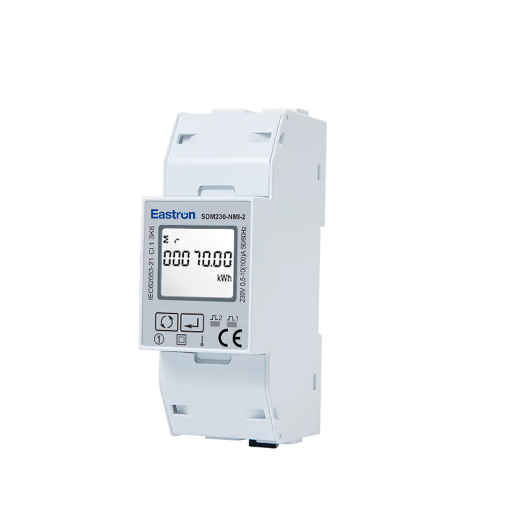
Dual RS485 Din Rail Single Phase Multi-function Solar PV/Zero Export Meter with 50mS Data Update for VPP Solution
Nov 24,2022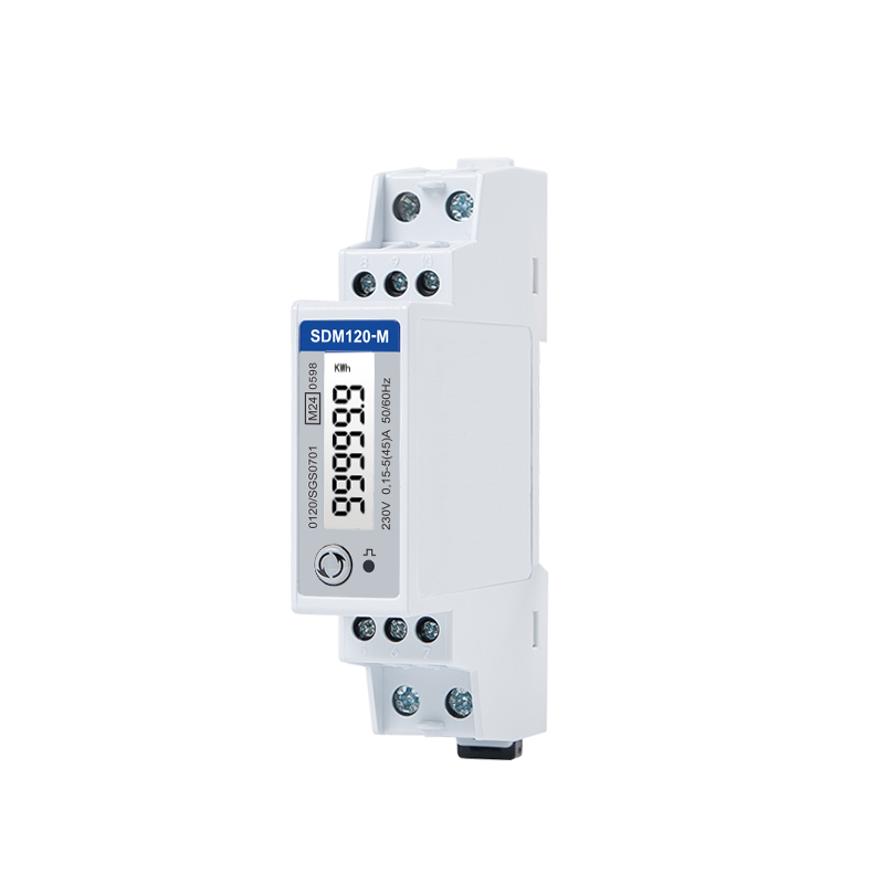
MID Din Rail Type Single Phase Multi-function Energy Meter for EV Charging Metering
Jul 26,2022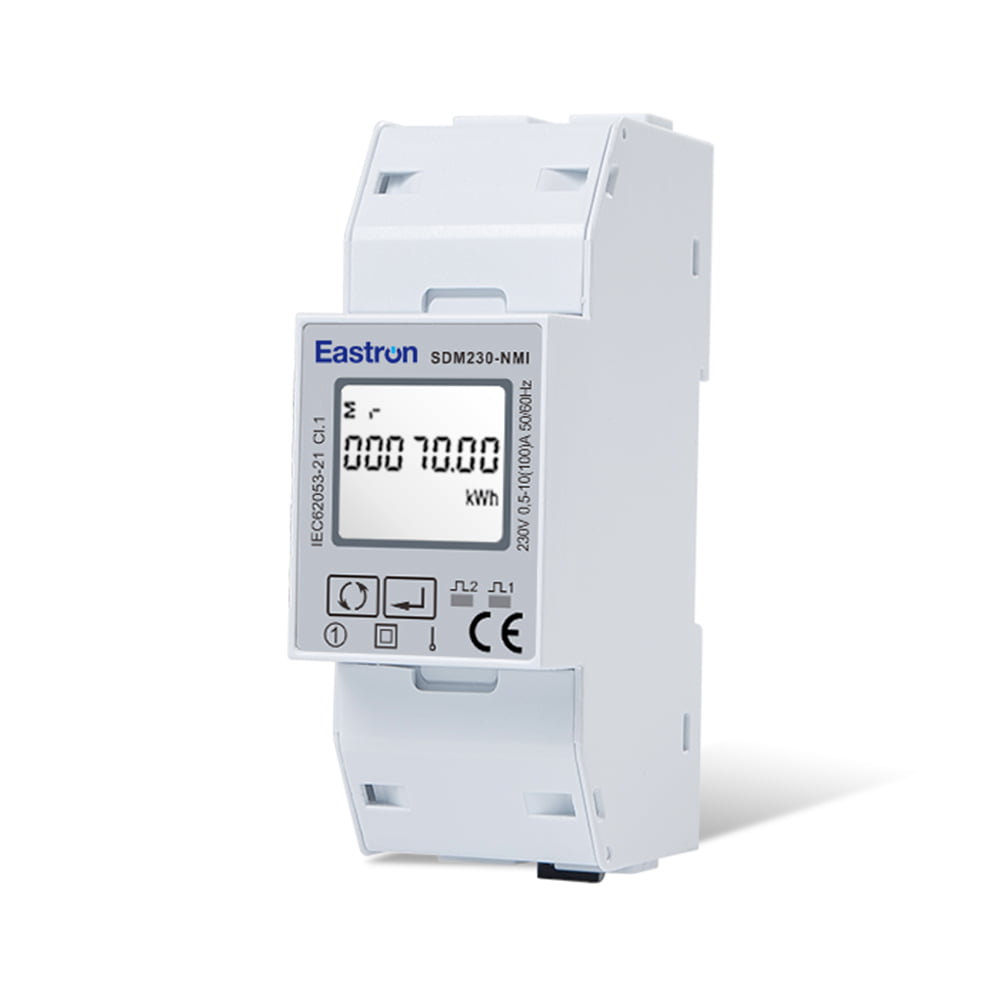
Din Rail Single Phase Multi-function Solar PV/Zero Export Meter with 50mS Data Update
Nov 24,2022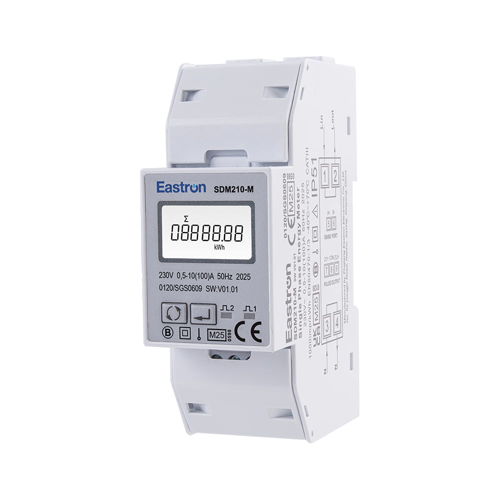
MID Approved Single Phase Energy Meter for EV Charging Metering
Nov 24,2022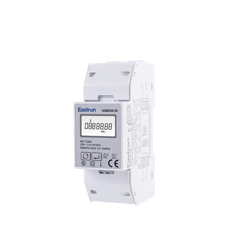
MID/ UL Approved Single Phase Din Rail Type Multi-function Energy Meter for EV Charging Metering
Nov 24,2022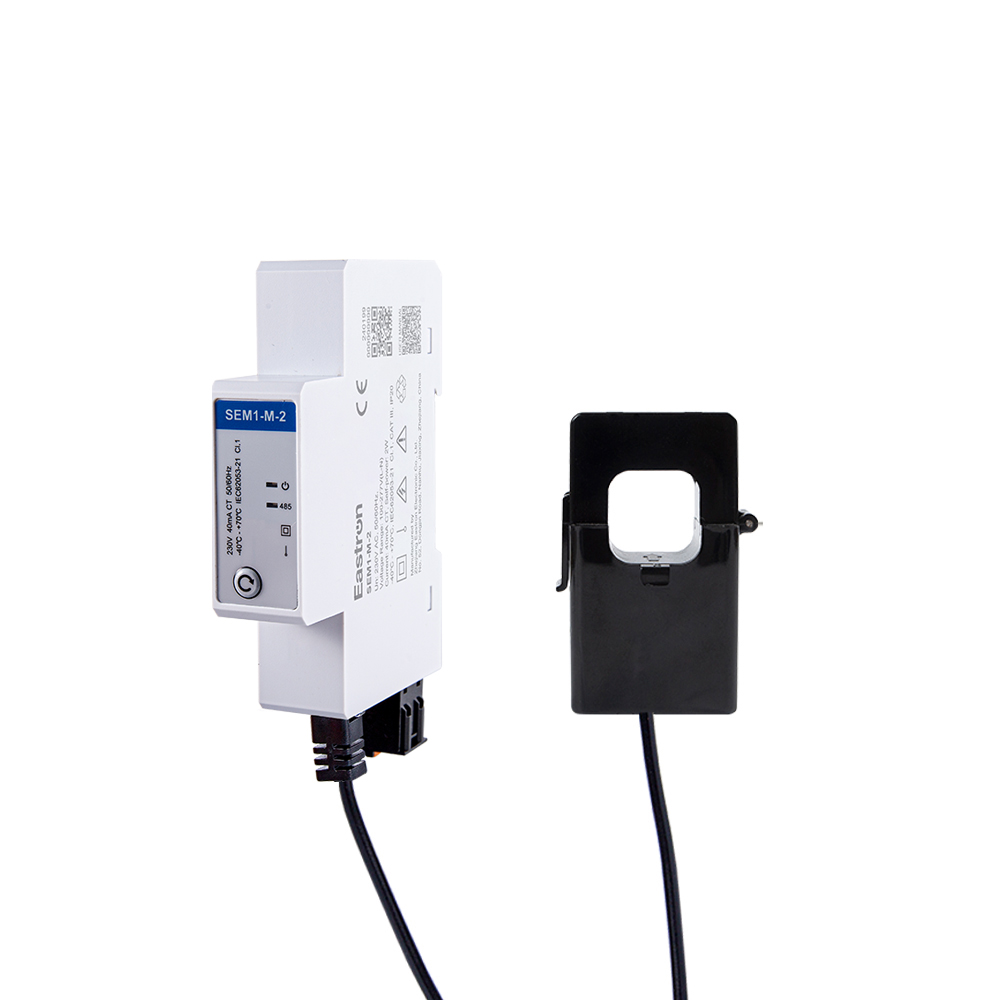
CT Type RS485 Modbus Single Phase Din Rail Energy Meter for PV Metering
May 30,2025Content
Modern electrical installations require more than a simple measurement of accumulated kilowatt-hours. Facility managers, solar system operators, equipment manufacturers, building owners, and energy service providers increasingly need a compact instrument that can measure multiple electrical parameters, communicate with supervisory systems, and provide dependable data at a practical installation cost. The 50 ms update single-phase multifunction energy meter is designed for this role.
Built for single-phase, two-wire applications, the meter combines direct current measurement up to 100 A, multifunction electrical monitoring, a backlit LCD, pulse outputs, and RS485 Modbus communication in one compact device. It measures active energy, reactive energy, voltage, current, active power, power factor, frequency, demand, and related values. Its fast 50 ms sampling and update capability makes it suitable for applications where a conventional energy counter cannot provide sufficient information or responsiveness.
The product is particularly well suited to residential distribution boards, small commercial buildings, photovoltaic systems, equipment panels, electric vehicle charging installations, energy management projects, and sub-metering applications. Bidirectional measurement also supports systems in which energy may flow both from the grid to the load and from a local generation source back toward the grid.
Manufactured by Eastron Electronic Co., Ltd., the meter reflects the company’s experience in electricity measurement, power analysis, communications, and energy management. Eastron combines product development in China and the United Kingdom with dedicated laboratory testing, standards-based quality control, and international production experience. This combination allows the meter to serve both straightforward local monitoring requirements and larger energy management architectures.
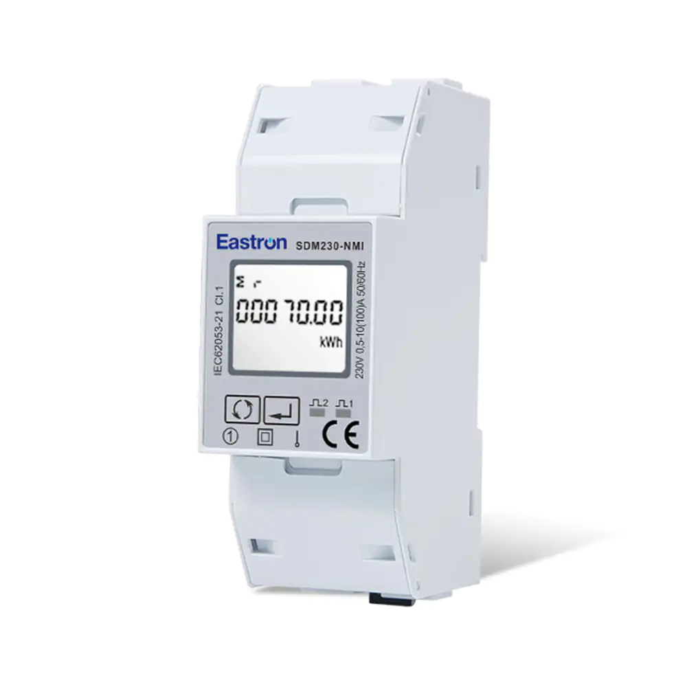
50mS Update Single Phase Multi-function Energy Meter
Single-phase circuits are common in homes, offices, retail premises, workshops, service facilities, and small industrial installations. Although the electrical arrangement is simpler than a three-phase system, the need for reliable information is not necessarily lower. A single circuit may supply lighting, HVAC equipment, pumps, server equipment, machinery, or charging equipment, and each load can contribute to energy costs and power-quality concerns.
A basic energy meter normally displays accumulated active energy. That information is useful for billing or periodic consumption analysis, but it does not explain why consumption changes or how the circuit is operating at a particular moment. Operators may also need to know whether voltage is within the expected range, whether a load is drawing excessive current, whether the power factor is deteriorating, or whether energy is being exported from a photovoltaic installation.
A multifunction energy meter addresses these needs by providing a broader electrical profile. The user can view several parameters locally through the display or retrieve them remotely through a communications network. This supports faster troubleshooting, more detailed energy reporting, and better decisions about load scheduling, equipment maintenance, and system upgrades.
The value of this approach is especially clear in distributed energy systems. A building with rooftop solar generation may consume power from the utility during some periods and export power during others. A meter that supports bidirectional measurement can record these changing energy flows more effectively than a one-direction device. It can therefore become an important measurement point for self-consumption analysis, solar performance evaluation, and energy management.
The meter is a 1P2W, single-phase, two-wire multifunction energy meter designed for direct connection applications. It supports a maximum direct load current of 100 A and has a rated voltage of 230 V. Its operational voltage range is 80% to 120% of the rated voltage, allowing it to operate across a practical range of normal supply conditions.
The device has a rated current of 10 A, a maximum current of 100 A, and a minimum current of 0.5 A. Its starting current is specified as 40 mA. These characteristics allow the meter to monitor both ordinary continuous loads and lighter circuits while maintaining a direct connection architecture suitable for many distribution applications.
The standard version provides two pulse outputs and one RS485 Modbus communication port. A related version, designated SDM230-NMI-2, provides two RS485 Modbus ports instead. This gives system designers a choice between pulse-based integration and dual-communication arrangements, depending on the architecture of the installation.
| Product characteristic | Specification or capability |
|---|---|
| Electrical system | Single-phase, two-wire AC system |
| Measurement connection | Direct connection |
| Rated voltage | 230 V |
| Operational voltage | 80% to 120% of rated voltage |
| Rated current | 10 A |
| Maximum current | 100 A |
| Minimum current | 0.5 A |
| Starting current | 40 mA |
| Update capability | 50 ms |
| Display | LCD with backlight |
| Communication | RS485 Modbus |
| Pulse outputs | Two pulse outputs on the standard version |
These features make the product more than a consumption counter. It is a compact measurement node that can operate as a local display instrument, a pulse-output meter, or a networked data source for a building management system, energy management platform, programmable logic controller, or supervisory control system.
One of the most distinctive features of this product is its 50 ms sampling and update capability. A faster update interval gives users access to more timely information about changing electrical conditions. This can be valuable where loads start and stop frequently, where equipment cycles rapidly, or where the operator needs to observe changes in power demand without waiting for a slow display refresh.
Fast updates are useful for commissioning and troubleshooting. When an engineer switches a load, the meter can provide a more immediate indication of the resulting current and power change. This can help identify unexpected consumption, verify whether a device is operating as intended, and compare the performance of different operating states.
The feature is also beneficial in energy management applications. Although the meter is not a protection relay or a high-speed power-quality recorder, timely measurements can help an energy management platform recognize changing demand patterns. For example, a controller may use current power readings to determine whether a flexible load should be delayed, whether a battery should charge, or whether solar generation is covering local consumption.
Compared with conventional low-function meters that update slowly or offer only accumulated energy, the 50 ms update capability gives system integrators a more responsive data source. This does not eliminate the need for suitable control equipment in safety-critical applications, but it improves the visibility available to monitoring and optimization systems.
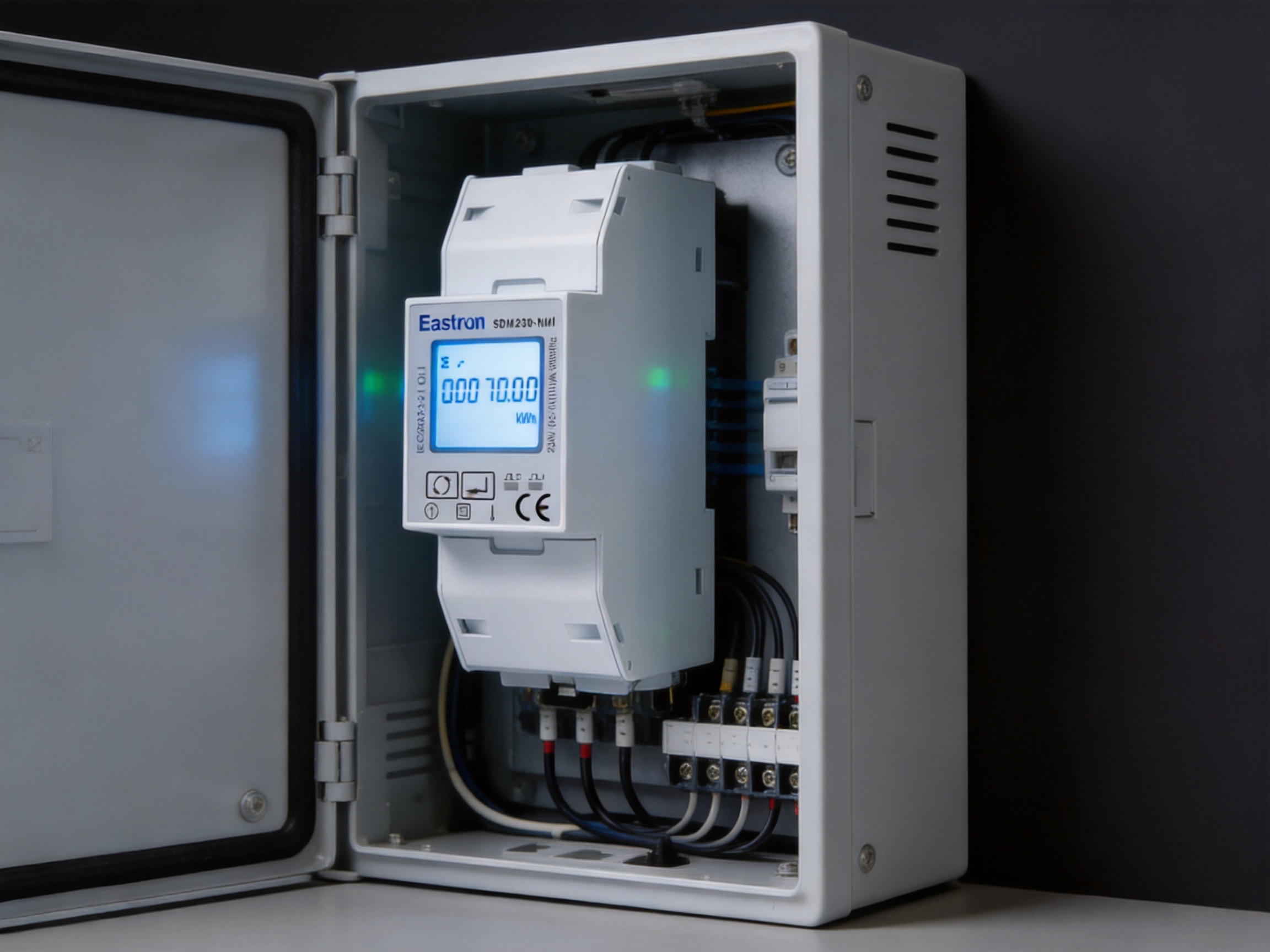
The meter measures active energy in kilowatt-hours and reactive energy in kilovar-hours. It also measures voltage, current, active power, power factor, frequency, and demand-related values. By combining these functions in one instrument, the product reduces the need for several separate meters and simplifies the design of a monitoring panel.
Active energy represents the electrical energy consumed or delivered by a circuit and is normally expressed in kilowatt-hours. It is the principal value used for consumption analysis, cost allocation, sub-metering, and energy reporting. The meter’s active energy performance is specified to IEC 62053-21 Class 1.0 and EN 50470-1/3 Class B requirements as stated for the product.
For a facility operator, an accurate active energy value supports comparison between departments, tenants, production lines, or time periods. It can also be used to verify whether efficiency improvements are producing measurable results. In a solar installation, bidirectional active energy measurement helps distinguish energy imported from the grid from energy exported or generated within the site.
Reactive energy is important in installations with inductive equipment such as motors, transformers, compressors, and fluorescent lighting systems. Although reactive energy does not perform useful mechanical work in the same way as active energy, it affects current flow and may influence losses, equipment loading, and utility charges.
The meter measures reactive energy according to the stated IEC 62053-23 Class 2 and IEC 61557-12 Class 2 performance specifications. Monitoring this value can help users understand the behavior of inductive loads and determine whether power factor correction or load-management measures may be appropriate.
Voltage and current provide the basic operating context for other electrical values. A current reading can reveal overload conditions, changing demand, or the effect of a newly connected load. Voltage readings can indicate supply variation, connection problems, or conditions that may affect sensitive equipment.
The stated accuracy for both current and voltage is 0.5% of range maximum. This provides a practical level of performance for general energy management, electrical distribution monitoring, and equipment-level measurement. Engineers should still select the correct measurement range and apply appropriate installation practices to achieve the best real-world results.
Instantaneous power helps operators understand what a circuit is doing at a particular moment. It can show the difference between standby consumption and active operation, identify peak demand periods, and support load profiling. The power measurement accuracy is specified as 1% of range maximum.
Power factor indicates the relationship between active power and apparent power. A low power factor may result from inductive loads, electronic power supplies, or other equipment characteristics. The meter specifies power factor accuracy of 1% of unity, with a resolution of 0.01. This level of information can support basic power factor assessment and help identify circuits that deserve further investigation.
Frequency measurement provides additional confirmation of supply behavior. The stated frequency accuracy is 0.2% of mid-frequency. This is suitable for general system monitoring and can help users identify deviations from the expected nominal frequency.
Accuracy is a central consideration when selecting an energy meter. A device may have an attractive display and extensive communication features, but unreliable measurement data can undermine the entire energy management project. The product addresses this concern through stated accuracy specifications for active energy, reactive energy, voltage, current, power, frequency, and power factor.
The active energy specification references IEC 62053-21 Class 1.0 and EN 50470-1/3 Class B. These references provide recognized performance frameworks for electricity metering. The reactive energy specification references IEC 62053-23 Class 2 and IEC 61557-12 Class 2. Together, these standards indicate that the meter has been developed with established international measurement expectations in mind.
Standards references are most valuable when supported by disciplined design, calibration, production inspection, and testing. Eastron’s stated laboratory capabilities include EMC, LVD, accuracy, and environmental testing according to IEC, EN, GB, and UL standards. Such testing supports the evaluation of electrical safety, electromagnetic compatibility, measurement behavior, and operation under environmental conditions.
For users comparing products from different suppliers, the relevant question is not only whether a meter lists many functions. It is also whether the supplier can demonstrate a repeatable process for validating those functions. A manufacturer with dedicated testing resources is better positioned to identify design weaknesses, control production quality, and maintain consistency across product batches.
The ability to measure up to 100 A through a direct connection is a major practical advantage for many single-phase installations. It avoids the need for an external current transformer in applications that fall within the meter’s specified direct-current range. This can reduce the number of components, simplify wiring, save panel space, and lower installation time.
Direct connection also makes the measurement path easier for installers and maintenance personnel to understand. Fewer external components can mean fewer connection points to inspect and fewer opportunities for ratio or polarity errors. In smaller distribution boards, the compact arrangement may be particularly valuable because panel space is often limited.
Current transformers remain appropriate for higher-current applications or installations with specific isolation and measurement requirements. However, for circuits up to 100 A, a direct-load meter can offer a simpler alternative. The decision should always be based on the electrical design, local regulations, conductor sizing, isolation requirements, and the manufacturer’s wiring instructions.
The meter is intended for use on a single-phase AC system with neutral. Correct wiring is essential. Qualified personnel should verify the supply voltage, current path, terminal connections, protective devices, conductor cross-section, enclosure requirements, and applicable electrical codes before energizing the device.
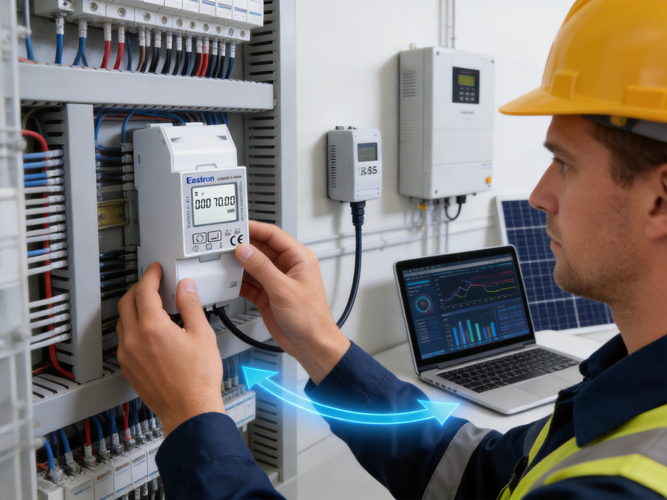
The backlit LCD provides a convenient local interface for commissioning, inspection, and routine operation. A technician can view measured values directly at the panel without connecting a laptop or opening a separate software interface. The backlight is useful in equipment rooms, electrical cabinets, and areas where ambient lighting is inconsistent.
Local visibility remains important even in highly automated installations. Communications networks can experience interruptions, configuration errors, or maintenance downtime. A display allows personnel to compare the physical installation with the data shown by the supervisory system and can help determine whether an issue lies in the electrical circuit, the meter, or the communication network.
For larger systems, RS485 Modbus provides a practical communications foundation. The interface supports communication addresses from 1 to 247, transmission speeds from 1200 bps to 38400 bps, selectable parity settings, and one or two stop bits. The stated maximum transmission distance is 1000 meters, subject to correct cable selection, network topology, grounding, termination, and electromagnetic conditions.
| Communication parameter | Available setting or performance |
|---|---|
| Protocol | Modbus RTU over RS485 |
| Address range | 1 to 247 |
| Transmission distance | Up to 1000 m maximum, depending on installation conditions |
| Transmission speed | 1200 bps to 38400 bps |
| Parity | None, odd, or even |
| Stop bits | 1 or 2 |
| Response time | Less than 100 ms |
| Standard output arrangement | Two pulse outputs plus RS485 Modbus |
| Alternative arrangement | Two RS485 Modbus ports |
Modbus RTU is widely used in energy management and automation because it is supported by many gateways, controllers, data loggers, and building management platforms. This broad compatibility helps integrators avoid dependence on a proprietary communication environment. It also allows the meter to be added to a broader network that may include power analyzers, temperature sensors, control devices, and other energy meters.
The pulse outputs offer another integration path. Pulse signals can be used by simple counters, legacy monitoring systems, or specialized data acquisition devices. This is useful when a complete Modbus network is not necessary or when the meter must interface with existing equipment that accepts energy pulses.
The market includes many low-cost energy counters and single-function meters. These products may be sufficient when the only requirement is to record total active energy. However, they may provide limited information for troubleshooting, energy optimization, and remote monitoring. The 50 ms update single-phase multifunction meter offers several advantages when a project requires more capability.
Instead of installing separate instruments for energy, current, voltage, power factor, frequency, and demand, the user can obtain these measurements from one multifunction meter. This reduces panel complexity and makes the data set easier to manage. It also helps ensure that measurements are collected from the same electrical point and under the same operating conditions.
The 50 ms update capability provides more responsive information than many basic meters designed primarily for slow cumulative readings. This is useful for commissioning, load profiling, solar monitoring, and applications involving equipment that changes operating state frequently.
For compatible circuits, direct measurement up to 100 A avoids the cost and installation effort of a separate current transformer. A simple measurement path can be an important advantage in retrofit projects, small commercial installations, and equipment panels.
The combination of pulse outputs and RS485 Modbus allows the meter to work with both simple and advanced systems. Users can read values locally, integrate the unit into a Modbus network, or connect pulse outputs to a compatible counter. The alternative dual-RS485 version provides an additional choice for system architects.
Bidirectional measurement makes the meter suitable for applications where energy flow changes direction. This is increasingly relevant to solar photovoltaic systems, battery storage, microgrids, and buildings with distributed generation. A unidirectional meter may not provide the same clarity when power is both imported and exported.
The stated references to IEC, EN, and IEC 61557 standards provide a stronger technical basis than an instrument described only through general marketing terms. Standards-based specifications help consultants and buyers compare products using measurable criteria.
Photovoltaic systems create a measurement environment in which energy direction and time-dependent behavior are important. During periods of strong solar generation, a building may produce more power than it consumes. At other times, the building may draw power from the grid. A meter with bidirectional measurement can help monitor these changing conditions.
Installed at a suitable point in the distribution system, the meter can provide data about imported and exported energy, current site demand, voltage, power, and power factor. This information can support solar self-consumption studies, inverter performance checks, and comparisons between generated power and building load.
The meter can also support hybrid energy systems that combine solar panels, battery storage, and grid supply. For example, a monitoring platform may examine active power and energy-flow data to determine whether a battery is charging from the grid, charging from solar generation, or discharging to support local loads. The meter is a measurement component in such a system; control decisions should be handled by equipment designed for that purpose.
Fast updates are useful when solar output changes because of cloud movement or when loads are switched on and off. While the device is not a dedicated irradiance sensor or a specialized power-quality analyzer, its electrical measurements can improve the visibility of how the distributed energy system interacts with the site supply.

Offices, retail stores, restaurants, and small commercial facilities can use the meter for tenant sub-metering, equipment monitoring, and energy-cost allocation. Individual circuits for HVAC, lighting, refrigeration, kitchens, or office equipment can be monitored separately. This allows facility managers to identify which loads are responsible for consumption changes.
In residential developments and apartment buildings, compact single-phase meters can help monitor common-area loads, individual apartments, heat pumps, EV chargers, or renewable energy systems. Remote communication can reduce the need for manual readings and support centralized reporting.
Original equipment manufacturers can integrate the meter into control panels, machines, pumps, compressors, and process equipment. The local display helps service engineers inspect the equipment, while Modbus communication can deliver operating data to a controller or cloud gateway.
Electric vehicle charging stations can create significant and variable loads. A multifunction meter can show charging current, power, energy, and power factor, helping operators evaluate the electrical impact of charging equipment. In installations with solar generation, the meter can also contribute to an understanding of whether charging is occurring during periods of local renewable production.
Workshops may have several single-phase machines with different operating cycles. Measuring each circuit can reveal standby losses, excessive demand, or unexpected changes in equipment behavior. The meter’s direct 100 A capability is appropriate for many smaller circuits, subject to the electrical design.
Energy service providers often need to collect data from existing buildings without major electrical modifications. A compact direct-connected meter with standard Modbus communication can be practical for retrofit projects. The installer can place meters at selected distribution points and send the measurements to a central platform for baseline development and savings verification.
Product performance depends not only on the published specification but also on the manufacturer’s ability to control design, components, software, assembly, inspection, and testing. Eastron Electronic Co., Ltd. is headquartered in Jiaxing, Zhejiang, China, in a manufacturing region with close access to major technology and industrial centers. The company develops and produces electricity meters, power analyzers, current sensors, communication modules, and energy management systems.
This product range is significant because it indicates a focus on the wider measurement ecosystem rather than a single isolated device. Experience with power analyzers, sensors, communications, and management systems can help a manufacturer understand how an energy meter will be used within a complete application. Such knowledge supports more practical interface design and better compatibility with monitoring architectures.
Eastron maintains development teams in China and the United Kingdom. This international development structure can contribute different perspectives on product requirements, technical standards, application practices, and customer expectations. Cooperation with universities and research institutions further supports the company’s stated investment in new technologies and product development.
The company reports expertise in software, embedded software, and hardware, along with patented technologies in these areas. A multifunction energy meter requires coordination among voltage and current sensing, signal processing, measurement algorithms, display control, communications, data storage, and protective design. Internal capability across these disciplines can improve the consistency of the final product.
Embedded software is particularly important in a device that provides multiple measurements and communications settings. The firmware must process sampled electrical signals, calculate measurement values, manage display pages, store configuration parameters, respond to Modbus requests, and control pulse outputs. A disciplined software development process is therefore as important as the physical circuitry.
Eastron has established a professional laboratory capable of performing EMC, LVD, accuracy, and environmental tests according to IEC, EN, GB, and UL standards. These capabilities support product validation at several levels.
Accuracy testing examines whether the meter produces readings within specified limits under different electrical conditions. EMC testing evaluates whether the device can operate properly in the presence of electromagnetic disturbances and whether it avoids creating unacceptable interference. LVD-related testing supports the evaluation of electrical safety. Environmental testing helps assess operation under relevant temperature, humidity, and other conditions.
Having these capabilities within the company can improve the speed of design verification and troubleshooting. Engineering teams can test prototypes, investigate failures, compare design revisions, and confirm corrective actions more efficiently. It also supports more controlled product release and ongoing quality management.
The company follows the ISO 9001 quality management system. A quality management system provides a framework for documented processes, corrective actions, supplier control, inspection, traceability, and continual improvement. While certification alone does not guarantee that every product is suitable for every application, it is an important indicator that manufacturing activities are organized around repeatable quality processes.
Eastron’s products and services have been supplied to more than 50 countries across Europe, Asia-Pacific, America, the Middle East, and Africa. International supply experience requires attention to different standards, electrical systems, communications expectations, documentation requirements, and after-sales support needs. It also encourages the manufacturer to design products that can be integrated into varied installation environments.
A dependable energy meter begins with a controlled product specification. Electrical ranges, accuracy requirements, communication behavior, display functions, environmental limits, and safety objectives must be defined before detailed design work begins. These requirements guide component selection and verification activities.
The hardware design must accommodate accurate voltage and current sensing, isolation where required, signal conditioning, microcontroller processing, display operation, communications, pulse generation, and protection against abnormal conditions. Component tolerances and thermal behavior must be considered because measurement accuracy can change with temperature, supply variation, and long-term operation.
Firmware development then converts electrical signals into usable measurement values. Algorithms must distinguish active and reactive energy, calculate power factor and frequency, maintain cumulative energy registers, and communicate the results through the selected protocol. Configuration functions such as address, baud rate, parity, and stop bits must be handled consistently so that installers can integrate the device correctly.
Production assembly requires controlled handling of electronic components, circuit boards, terminals, displays, and housings. Inspection procedures can identify soldering defects, incorrect component placement, mechanical damage, or connection problems. Functional testing can verify display behavior, communications, pulse outputs, measurement response, and basic operating states before products leave the production line.
Final calibration and verification are especially important for measurement equipment. Test systems can apply known voltage, current, phase relationships, and frequencies to confirm the response of each unit or production batch. Environmental and EMC validation can then provide additional confidence that the design will operate as intended outside the laboratory.
The strength of a professional manufacturer is therefore not a single feature. It is the combination of engineering expertise, documented production procedures, laboratory capability, standards awareness, inspection, and customer support. These elements help turn a technical design into a consistent commercial product.
RS485 Modbus is widely accepted in industrial and building automation because it is simple, robust, and supported by a broad range of equipment. A meter with this interface can communicate with a gateway, programmable controller, building management system, industrial computer, or data logger.
When planning an RS485 network, installers should use suitable twisted-pair cable, observe the recommended bus topology, assign unique addresses, and configure all devices with compatible baud rate, parity, and stop-bit settings. Proper termination and grounding practices are also important, especially on long cable runs or in electrically noisy environments.
The meter supports communication addresses from 1 to 247, allowing many devices to be individually identified within a network. The actual number of meters that can be placed on one segment depends on the master device, transceiver loading, cable characteristics, network design, and local installation conditions.
A stated response time of less than 100 ms supports practical polling in many monitoring applications. System designers should determine the required polling interval based on the number of connected devices, the baud rate, the register set being read, and the importance of each measurement. Fast local meter updates and network polling are related but not identical functions; a complete system should be designed with both in mind.
Only qualified electrical personnel should install and commission the meter. Before installation, the system voltage and current should be compared with the meter’s ratings. The installer should confirm that the application is a compatible single-phase, two-wire system and that the expected maximum current does not exceed the direct measurement limit.
Correct polarity and terminal assignment are important for accurate energy direction and power calculations. Incorrect wiring may result in abnormal readings, reversed energy flow, or communication and display results that do not reflect the actual circuit. The wiring diagram supplied with the product should be followed carefully.
After installation, the technician should verify the voltage reading, compare current readings with an independent instrument where appropriate, confirm the power factor sign and direction, check the frequency, and test the pulse or Modbus output. If the meter is connected to a larger management platform, the technician should also confirm the device address, baud rate, parity, stop bits, register mapping, scaling, and unit interpretation.
For solar or bidirectional applications, commissioning should include checks under both import and export conditions if those operating states are available. This helps verify that energy direction is being interpreted correctly by the meter and by the supervisory software.
Environmental conditions should also be considered. The meter should be installed in an enclosure appropriate for the location, protected from excessive moisture, contamination, vibration, heat, and unauthorized access. The equipment should not be used outside its specified electrical or environmental limits.
Measurement is the foundation of energy efficiency. Without reliable data, organizations may rely on assumptions rather than evidence. A multifunction meter can provide the information needed to establish a baseline, identify high-consumption circuits, evaluate improvement measures, and verify results over time.
For example, a facility may discover that a ventilation system continues to consume significant power outside operating hours. Current, power, and energy data can support a change in scheduling. A workshop may find that a motor has a persistently low power factor. A retail store may compare refrigeration consumption with ambient conditions and operating schedules. A solar operator may compare site demand with renewable generation throughout the day.
The meter can also support maintenance decisions. A gradual increase in current at a familiar operating point may indicate mechanical wear, process changes, or electrical problems. A voltage deviation may explain equipment behavior that would otherwise be difficult to diagnose. The meter is not a substitute for a complete predictive maintenance system, but it provides useful electrical evidence.
When multiple meters are installed across a facility, managers can compare loads and prioritize projects. This distributed approach can be more informative than measuring only the main incoming supply because it shows where energy is being used. Standard Modbus communication makes it practical to bring these measurements into a central dashboard.
Buyers should begin by identifying the electrical system and maximum expected current. The product is intended for single-phase, two-wire AC applications and direct connection up to 100 A. If the installation requires three-phase measurement, much higher current, revenue-grade certification for a particular jurisdiction, or specialized power-quality analysis, a different meter may be more suitable.
The next consideration is the measurement set. If the project needs only accumulated active energy, a basic meter may be sufficient. If the project requires voltage, current, power, reactive energy, power factor, frequency, demand, and bidirectional measurement, the multifunction design provides greater value and avoids future replacement when monitoring requirements expand.
Communication requirements should also be considered. The standard version is appropriate where pulse outputs and one RS485 Modbus port are required. The alternative version with two RS485 Modbus ports may better suit systems that need separate communication paths or a particular integration arrangement.
Buyers should review the applicable standards, local approval requirements, installation environment, display visibility, wiring space, and support expectations. They should also confirm the required register information, pulse configuration, and software compatibility before large-scale deployment.
The meter is designed for RMS measurement on a single-phase AC system with one phase and neutral, commonly described as a 1P2W system.
The maximum direct current is 100 A. The rated current is 10 A, the minimum current is 0.5 A, and the starting current is specified as 40 mA.
It indicates a fast sampling and update capability that provides more responsive information about changing electrical conditions. It is useful for monitoring loads that start, stop, or vary frequently.
The meter measures active energy, reactive energy, voltage, current, active power, power factor, frequency, demand-related values, and other associated electrical parameters.
Yes. Bidirectional measurement makes it suitable for applications such as solar photovoltaic systems, battery systems, and installations where energy may be imported from or exported to the grid.
Yes. It includes an LCD with backlighting so that measurements and operating information can be viewed locally during commissioning and routine inspection.
The meter uses RS485 Modbus RTU. The standard version also provides two pulse outputs, while the SDM230-NMI-2 version provides two RS485 Modbus ports.
The stated maximum transmission distance is 1000 meters. Actual performance depends on cable type, network topology, baud rate, termination, grounding, electromagnetic conditions, and the quality of the installation.
Transmission speeds from 1200 bps to 38400 bps are supported. Parity can be set to none, odd, or even, and one or two stop bits are available.
Active energy is specified to IEC 62053-21 Class 1.0 and EN 50470-1/3 Class B. Reactive energy is specified to IEC 62053-23 Class 2 and IEC 61557-12 Class 2. Power accuracy is 1% of range maximum, while voltage and current accuracy are 0.5% of range maximum. Frequency accuracy is 0.2% of mid-frequency, and power factor accuracy is 1% of unity.
For circuits within the 100 A limit, direct connection can eliminate the need for an external current transformer. This may reduce wiring, panel space, component count, and installation complexity.
Yes. Its bidirectional measurement, multifunction data, fast updates, and Modbus communication make it suitable for many solar photovoltaic monitoring applications. The complete installation must still be designed according to the inverter, grid connection, local regulations, and safety requirements.
The manufacturer reports a professional laboratory capable of EMC, LVD, accuracy, and environmental testing according to IEC, EN, GB, and UL standards. The company also follows the ISO 9001 quality management system.
No. It is a measurement and communication device, not a substitute for properly selected protective equipment, isolation devices, circuit breakers, fuses, or safety control systems.
Technicians should verify the electrical system, rated voltage, maximum current, terminal wiring, polarity, protective equipment, communication settings, pulse configuration, display readings, and integration with the supervisory system. For bidirectional applications, import and export behavior should be checked whenever possible.
The 50 ms update single-phase multifunction energy meter provides a practical combination of speed, measurement breadth, direct-load capability, display visibility, and communication flexibility. It measures the electrical parameters needed for modern energy management while supporting applications that range from local panel monitoring to networked commercial and industrial systems.
Its 100 A direct connection simplifies many installations, while the LCD, pulse outputs, and RS485 Modbus interface provide several ways to access and share data. The ability to measure bidirectional energy is particularly valuable for solar photovoltaic systems, battery storage, and buildings with distributed generation. Its stated accuracy and standards references provide a structured basis for technical evaluation.
The product is also supported by a manufacturer with experience in electricity meters, power analyzers, current sensors, communication modules, and energy management systems. Eastron’s reported research and development resources, China and United Kingdom development teams, professional testing laboratory, ISO 9001 quality management system, and international supply experience strengthen the product’s position in the energy measurement market.
For users who need more than a basic energy counter but do not require a large multifunction power analyzer, this meter offers a balanced solution. It delivers detailed electrical information in a compact format and can help organizations measure, understand, and improve the performance of single-phase electrical systems.
IEC 62053-21, Electricity Metering Equipment: Particular Requirements for Static Meters for Active Energy.
EN 50470-1, Electricity Metering Equipment: General Requirements, Tests, and Test Conditions.
EN 50470-3, Electricity Metering Equipment: Particular Requirements for Static Meters for Active Energy.
IEC 62053-23, Electricity Metering Equipment: Particular Requirements for Static Meters for Reactive Energy.
IEC 61557-12, Electrical Safety in Low-Voltage Distribution Systems: Power Metering and Monitoring Devices.
ISO 9001, Quality Management Systems: Requirements.
Modbus Organization, Modbus Application Protocol and Serial Line Communication Principles.
Manufacturer product information for the 50 ms update single-phase multifunction energy meter.
Manufacturer information concerning electricity measurement products, laboratory testing, research and development, quality management, and energy measurement solutions.
Your email address will not be published. Required fields are marked *

We develop and produce high performance electricity meters, power analyzers, current sensors, communication modules and management systems.
Address:NO. 52, Dongjin Road, Nanhu, Jiaxing, Zhejiang, China
Copyright @ Eastron Electronic Co., Ltd. All rights reserved
