

 English
 Español
 Deutsch
 中文简体


Product Consultation
Your email address will not be published. Required fields are marked *
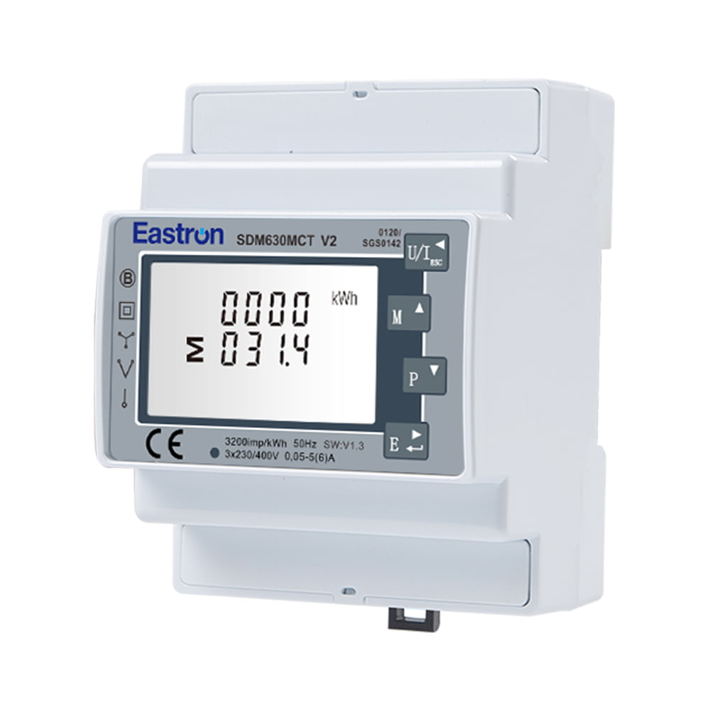
MID Approved CT Type Din Rail Three Phase Multi-function Solar PV /Zero Export Meter for PV Metering
Nov 24,2022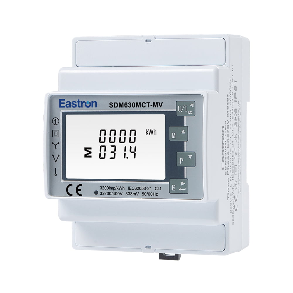
RCM CT Type Din Rail Three Phase Multi-function Solar PV /Zero Export Meter for PV Metering
Aug 03,2022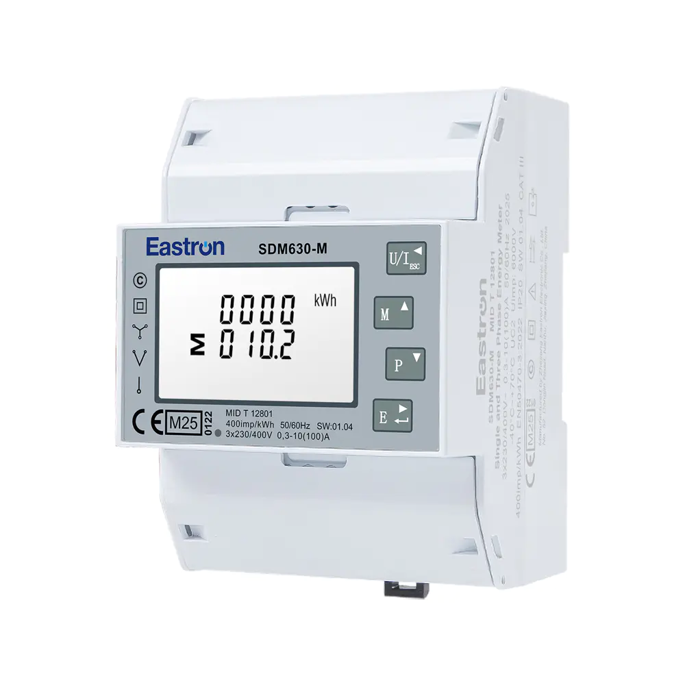
MID Din Rail Three Phase Multi-function Solar PV /Zero Export Meter for PV Metering
Aug 02,2022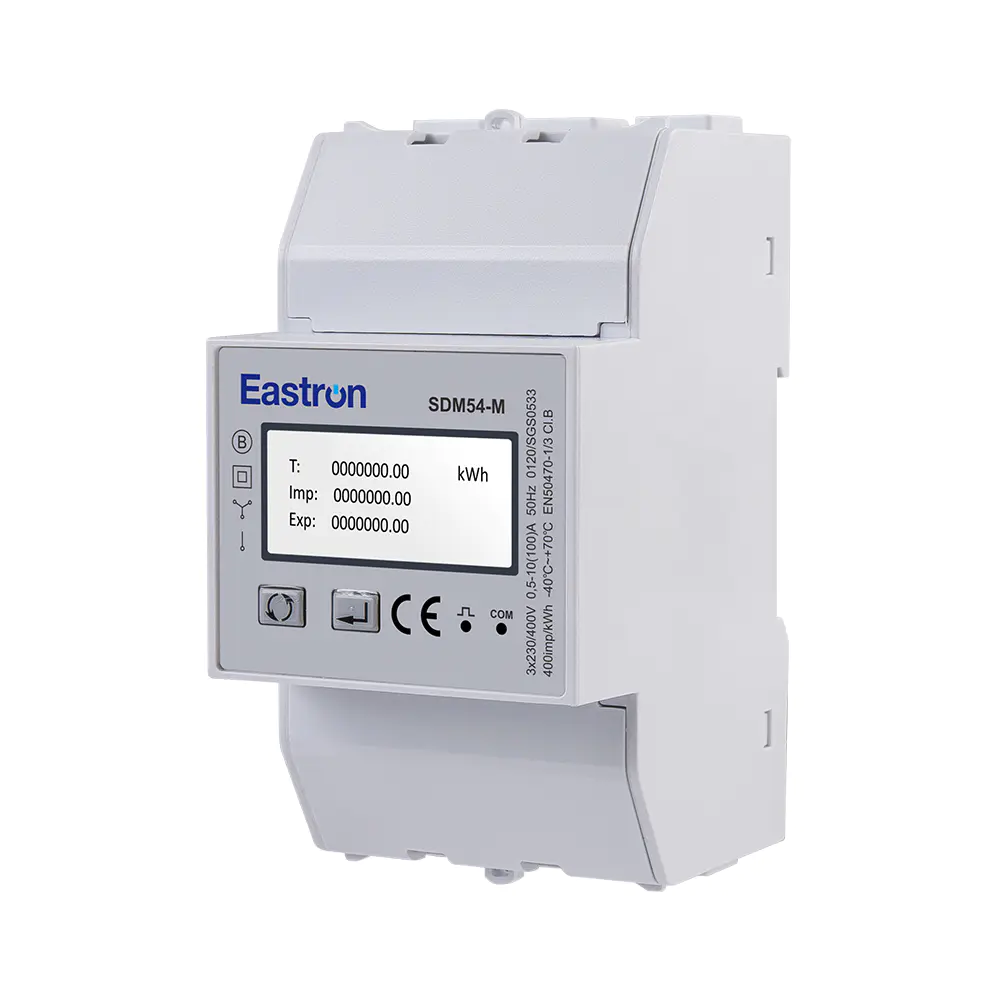
MID 3 Modules Din Rail Three Phase Multi-function Solar PV /Zero Export Meter for PV Metering
Aug 02,2022
Wifi & LoRa Three Phase Din Rail Energy Meter for PV Metering
Sep 19,2025
MID Din Rail Single Phase Multi-function Solar PV /Zero Export Meter for PV Metering
Nov 24,2022Content
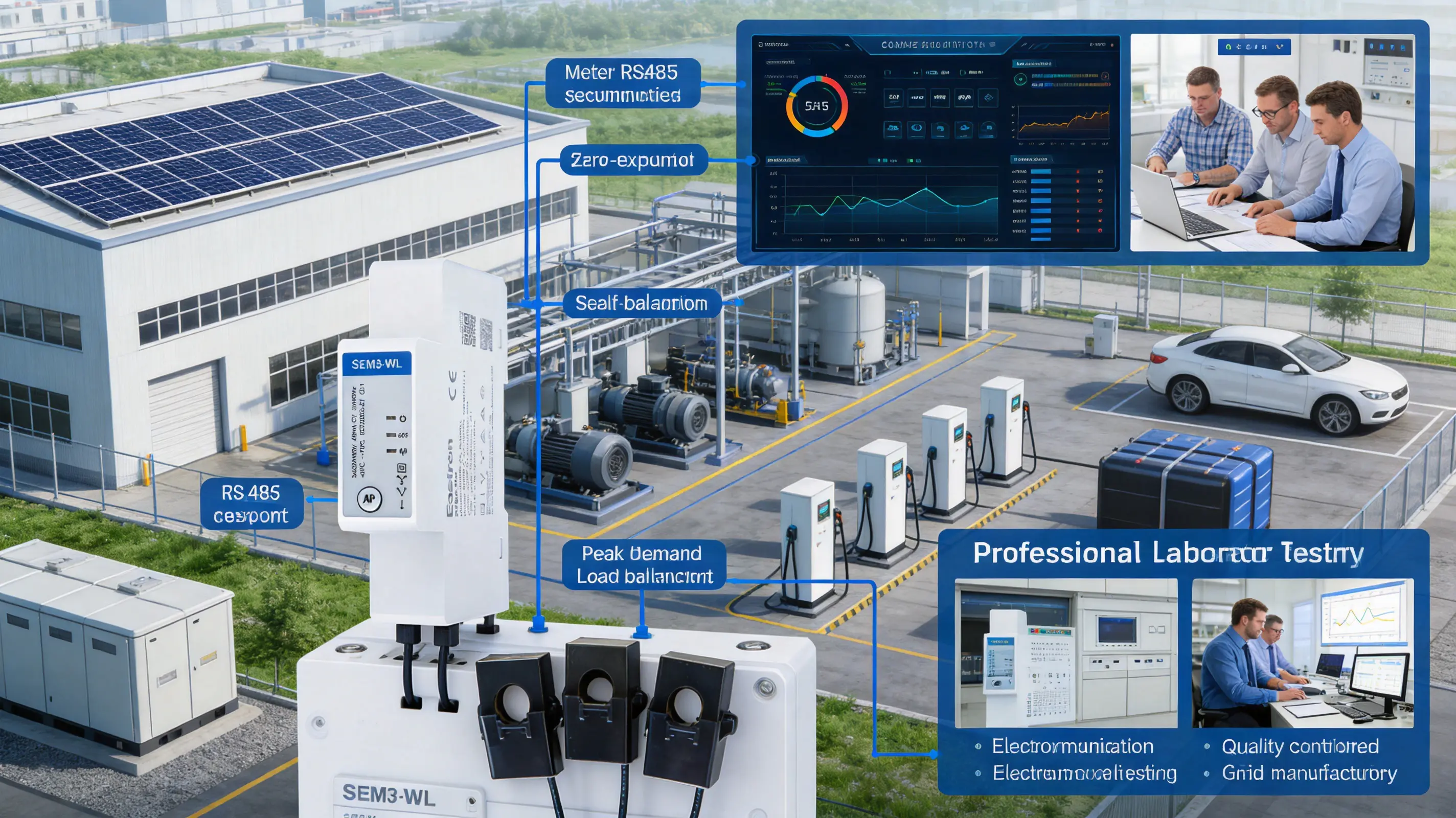
The expansion of distributed solar generation has changed the way electricity is measured, managed, and controlled. Residential buildings, commercial facilities, industrial sites, and energy communities increasingly need to understand not only how much electricity they consume, but also how much energy is generated, imported, exported, and exchanged between the grid and local loads. A suitable meter must therefore do more than record cumulative kilowatt-hours. It must provide accurate multi-parameter measurements, communicate with energy management systems, support flexible wiring arrangements, and operate reliably in installations where space, maintenance time, and commissioning costs are limited.
The SEM3-WL three-phase Wi-Fi multifunction solar PV and zero-export meter is designed for this type of application. It combines energy measurement, power monitoring, Wi-Fi connectivity, RS485 Modbus RTU communication, external current transformers, and selectable measurement modes in a compact DIN-rail-mounted enclosure. Its design supports 1P2W, 3P3W, and 3P4W electrical systems, allowing one device to serve a wide range of low-voltage metering requirements.
In addition to measuring voltage, current, power, frequency, power factor, and active and reactive energy, the meter can operate as one three-phase meter or as three independent single-phase meters. This flexibility makes it suitable for solar PV systems, zero-export control, building energy monitoring, industrial equipment, and distributed load measurement. The package includes three current transformers, helping simplify installation and reducing the need to source compatible sensors separately.
This article examines the meter’s operating concept, measurement capabilities, communications architecture, installation advantages, solar energy applications, and the manufacturing strengths behind its development. It also explains how the product can help system integrators improve visibility, reduce wiring complexity, and create more adaptable energy measurement solutions.
A solar PV installation produces electricity at a variable rate. Output changes with sunlight, weather, panel temperature, shading, and inverter operating conditions. At the same time, building demand changes according to occupancy, machinery, heating and cooling loads, appliances, and production schedules. Without real-time measurement, it is difficult to determine whether generated energy is being consumed locally, exported to the utility grid, or supplemented by grid power.
Traditional single-function meters may provide a cumulative energy reading, but they often do not provide the breadth or speed of information required by modern energy management systems. A solar application may require simultaneous monitoring of each phase voltage and current, total active power, reactive power, power factor, import energy, export energy, and frequency. It may also need a communication link to an inverter controller, building management platform, data logger, or cloud gateway.
The SEM3-WL addresses these requirements by combining measurement and connectivity in one compact device. Its measurements are based on RMS values, including harmonics, on three-phase AC systems. This is particularly useful where loads include variable-speed drives, switch-mode power supplies, LED lighting, data equipment, inverters, and other electronic devices that can introduce non-sinusoidal current waveforms.
For solar PV projects, the meter can be installed at a grid connection point, a distribution board, or a load-side monitoring location. When integrated with a control system, its readings can support decisions such as limiting inverter output, increasing local self-consumption, scheduling flexible loads, or preventing unwanted export to the grid.
The meter supports 1P2W, 3P3W, and 3P4W supplies. This allows the same product family to be used in single-phase systems, three-wire three-phase systems, and four-wire three-phase systems with a neutral connection. The rated input voltage is 3 × 230 V line-to-neutral or 400 V line-to-line, with a working range of 90 to 300 V AC line-to-neutral and 156 to 520 V AC line-to-line.
This broad operating range gives installers greater flexibility when applying the meter to different low-voltage networks. It also accommodates normal voltage variation in many commercial and industrial environments. The supported frequency range is 50 or 60 Hz, making the meter suitable for a wide range of international electrical systems.
One of the product’s most useful features is its ability to operate in two different measurement arrangements. In one configuration, the device functions as a single three-phase energy meter. This is appropriate for a three-phase PV inverter, a complete building supply, or a three-phase industrial load.
In the alternative configuration, the device operates as three independent single-phase meters. Each phase can then be assigned to a separate load. In this mode, three external current transformers can be configured with different current-transformer ratios. This is beneficial when a facility has several independent single-phase circuits with different load sizes or when a small number of circuits must be monitored without installing three separate meters.
Compared with a fixed-purpose meter, this arrangement can reduce panel space, wiring requirements, and equipment inventory. It also gives system designers the ability to adapt the same meter to changing project requirements. A building that initially requires three single-phase load measurements may later be reorganized as a three-phase system, subject to the application and configuration requirements.
The meter records and communicates a wide range of electrical parameters. These include phase and line voltage, current, frequency, active power, reactive power, apparent power, power factor, and active and reactive energy. Energy can be measured in kilowatt-hours, kilovolt-ampere-reactive hours, and kilovolt-ampere-hours.
Four-quadrant measurement enables the meter to distinguish energy flow in both directions and to account for different combinations of active and reactive power. This is important in installations where electricity may be imported from the grid at one moment and exported from a PV system at another. It is also relevant in facilities containing motors, transformers, power-factor correction equipment, and inverter-based loads.
Maximum demand information can help facility operators understand peak loading. This can support capacity planning, tariff management, transformer utilization studies, and the identification of demand peaks caused by production equipment or simultaneous building loads.
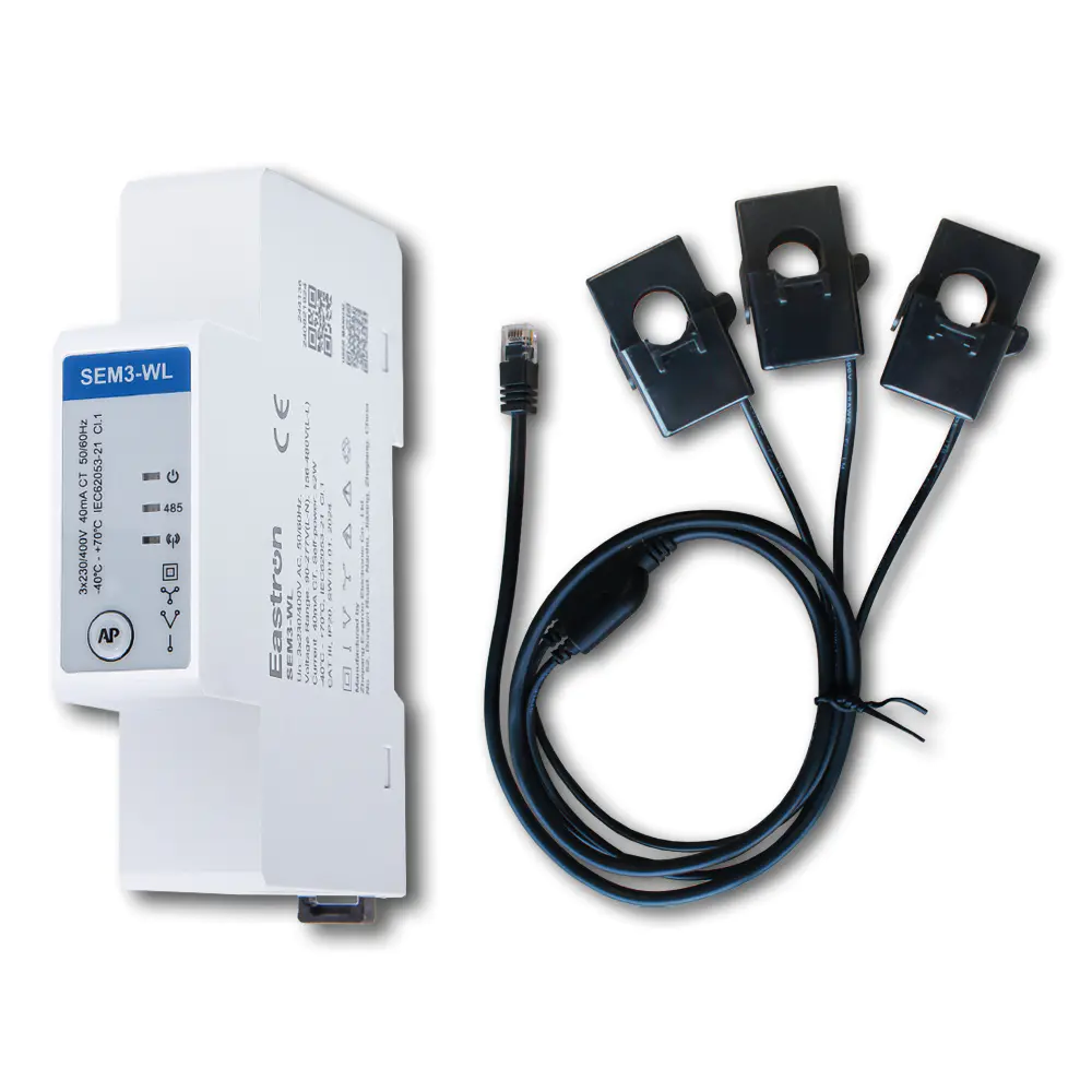
Three Phase Wi-Fi Multi-function Solar PV /Zero Export Meter for PV Metering
The SEM3-WL provides Class B active-energy accuracy, with the published active-energy accuracy specified as ±1 percent. Reactive-energy accuracy is specified as ±2 percent. Power measurement accuracy is specified at ±1 percent in accordance with the stated IEC 61557-12 Class 1 reference. These specifications make the device suitable for many monitoring, control, allocation, and solar-management applications.
Measurement accuracy should always be considered together with the complete installation. Correct current-transformer selection, appropriate current-transformer orientation, secure connections, correct phase assignment, and proper ratio configuration are essential. The meter’s inclusion of three current transformers helps create a matched product package, while the configuration process remains an important part of commissioning.
The stated current accuracy varies according to the measured current range. The meter provides ±0.5 percent accuracy from 4 A to 120 A, ±1 percent from 1 A to 4 A, and ±3 percent from 0.06 A to 1 A. This range reflects a practical balance between measurement performance at normal operating currents and the challenges associated with very low current levels.
For solar and building applications, this means that the selection of current-transformer rating should be based on the expected operating current rather than only the maximum possible current. A transformer that is too large may reduce the effective resolution at low load, while an unsuitable transformer may be exposed to excessive current. Proper engineering design ensures that the measurement range is used effectively.
Voltage accuracy is specified as ±0.5 percent, while frequency accuracy is specified as ±0.2 percent. Power-factor accuracy is specified as ±0.1. These measurements help operators investigate voltage imbalance, changing grid conditions, poor power factor, and equipment behavior.
For PV applications, voltage and frequency information can be used alongside inverter data to assess the condition of the connection point. In industrial facilities, power-factor readings can reveal the effects of inductive motors or ineffective correction equipment. In commercial buildings, the combined view of voltage, current, and power factor can provide a clearer picture of how individual loads affect the electrical system.
Active-power data is updated every 50 milliseconds through RS485 and every 100 milliseconds through Wi-Fi, according to the published specifications. This relatively fast update capability is valuable in systems that must respond to changing generation and consumption conditions.
Zero-export control is one example. If a PV system is producing more power than local loads can consume, a controller may need to reduce inverter output or activate a controllable load. Fast data availability helps the controller identify changes quickly. The meter is not, by itself, a complete export-control system; however, it provides the measurement data required by a properly designed control architecture.
In Total mode, imported and exported energy are measured separately. This mode provides a detailed view of bidirectional energy flow. It is useful where the operator wants to distinguish energy purchased from the grid from energy delivered to the grid.
Separate import and export records can support energy reporting, operational analysis, tariff assessment, and performance verification. For a solar installation, the data can help determine the level of onsite self-consumption and the amount of generation that is not used locally.
In PV mode, imported and exported energy are balanced first, and the balanced value is then counted as imported or exported energy. This approach is intended for applications where the measurement objective is related to photovoltaic energy management or zero-export operation.
The distinction between Total mode and PV mode allows the meter to serve different reporting philosophies. A site owner seeking a detailed record of both directions of energy flow may prefer Total mode. A system designed around PV balancing may benefit from PV mode, depending on the control logic, local regulations, and energy-management platform being used.
Before commissioning, the installer should confirm which mode corresponds to the project’s metering rules and control objectives. The selected mode should be documented so that operators understand how the recorded energy values are calculated.
The RS485 interface uses Modbus RTU, a widely adopted protocol for industrial automation and energy-management systems. The communication address can be set from 1 to 247, enabling multiple devices to share a properly designed RS485 network.
The interface operates in half-duplex mode, uses floating-point data, and supports transmission speeds from 2400 bps to 115200 bps. Parity can be set to none, odd, or even, and stop bits can be configured as one or two. The maximum stated transmission distance is 1000 meters, although the practical distance depends on cable quality, topology, termination, electromagnetic conditions, baud rate, and grounding arrangements.
RS485 is particularly valuable in industrial and commercial sites where stable wired communications are preferred. A twisted-pair cable can connect the meter to a local controller, programmable logic controller, data concentrator, building management system, or energy gateway. Wired communication also avoids dependence on wireless signal strength in metal cabinets, plant rooms, or reinforced concrete buildings.
The integrated Wi-Fi interface uses Modbus TCP and operates in the 2.4 GHz to 2.5 GHz RF band. It supports IEEE 802.11 b/g/n and provides a stated maximum RF power of less than 20 dBm. The published range is up to 30 meters indoors and 50 meters outdoors, subject to local conditions.
Wi-Fi can simplify retrofit projects because it may eliminate the need for a dedicated communication cable between the meter and a nearby monitoring platform. It can also support faster deployment in small commercial sites, residential solar installations, temporary energy audits, and locations where cable routing is difficult.
Wireless performance depends on building materials, cabinet construction, network congestion, antenna placement, access-point location, and local interference. For critical control applications, the availability of RS485 provides an alternative wired communication path. The ability to choose between Wi-Fi and RS485 is a major practical advantage compared with meters that provide only one communication method.
A reliable energy-monitoring system should define communication requirements before installation. These include the selected interface, device address, baud rate or network settings, register map, polling interval, data format, and time synchronization method used by the supervisory system.
For RS485 networks, installers should use suitable shielded twisted-pair cable where appropriate, maintain a daisy-chain topology, avoid unnecessary star connections, and apply termination and biasing according to the system design. For Wi-Fi networks, the access point should provide adequate coverage at the installation location, and network security policies should be considered during commissioning.
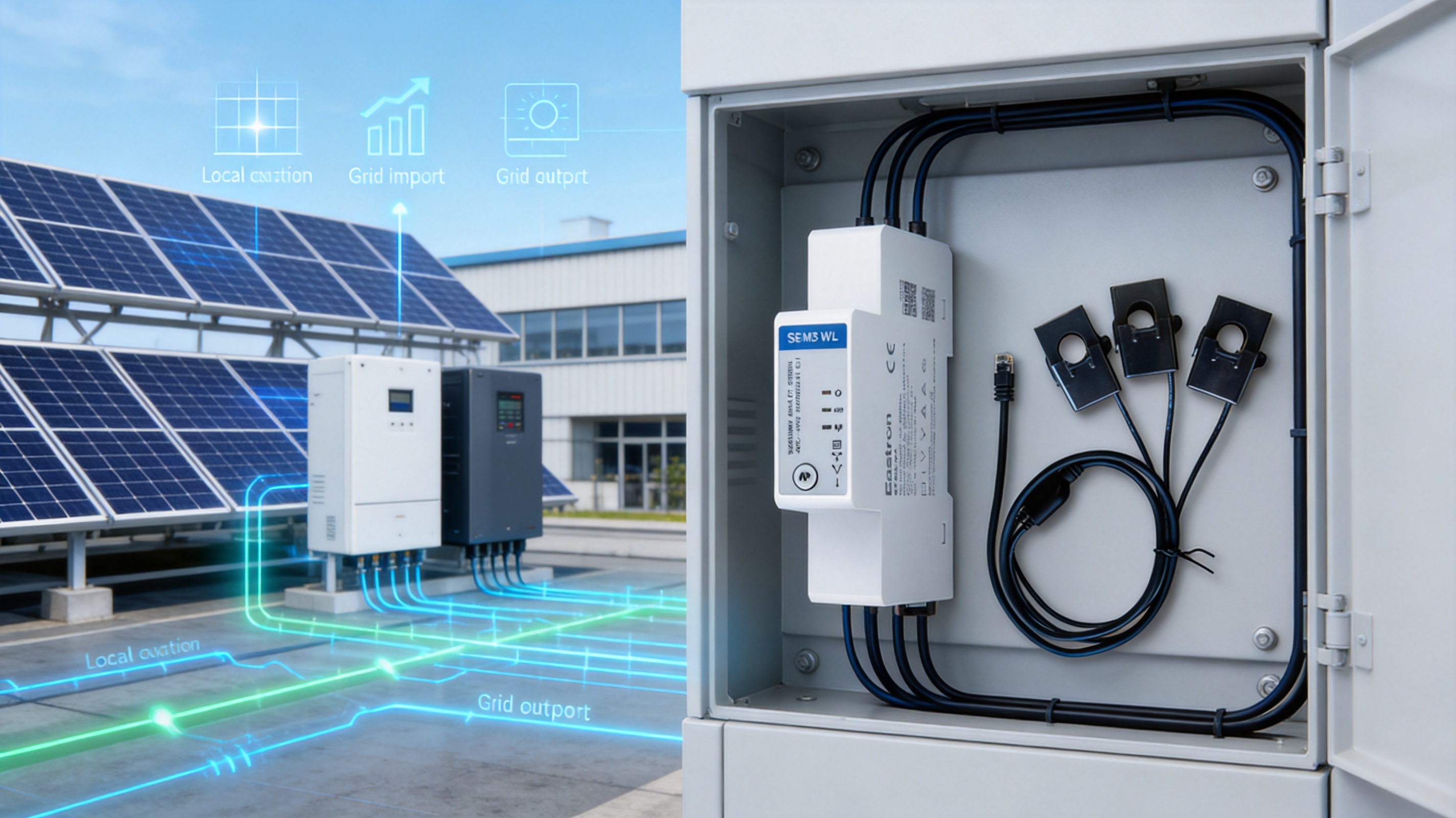
Space is often limited in distribution boards and control panels. The SEM3-WL is designed with a compact one-modular-width form factor for DIN-rail installation. This allows it to be placed alongside protective devices, contactors, communication equipment, and other control components without occupying the space required by a larger panel meter.
A compact enclosure can reduce panel size, simplify retrofit installation, and improve equipment layout. It may also lower transportation and enclosure costs for system builders. However, adequate clearance, thermal conditions, accessibility, and compliance with local installation rules must still be maintained.
The meter uses spring terminals or RJ terminals for its connections. Spring terminals can reduce tightening-related installation errors and provide a convenient connection method for suitable conductors. RJ connections can simplify the attachment of current transformers or communication accessories, depending on the wiring arrangement. The result is an installation approach designed to reduce wiring time and maintenance effort.
The product package includes three current transformers. Providing the sensors together with the meter helps installers avoid compatibility uncertainty and reduces the number of separate components that must be ordered. The current-transformer arrangement also supports the product’s three-phase and three-independent-single-phase measurement modes.
Incorrect phase sequence can affect the interpretation of three-phase measurements and may cause problems in equipment that relies on phase relationships. The meter provides a warning when a phase-sequence error occurs. This feature can help installers identify wiring issues during commissioning rather than discovering them later through unexpected power readings or incorrect energy direction.
A phase-sequence warning does not replace good installation practice. Voltage leads and current-transformer connections must still be identified and matched correctly. Nevertheless, an onboard warning function can shorten troubleshooting time and improve commissioning confidence.
In a grid-connected PV system, the meter can monitor the electrical exchange at the point where the installation connects to the utility network. It can report whether the site is importing or exporting energy and can provide the power data required to compare generation with local demand.
When installed as part of an energy-management system, the meter can help determine whether the PV system is being used efficiently. Operators can compare production periods with building load profiles, identify excessive export, and evaluate opportunities for shifting loads into periods of strong solar generation.
Zero-export systems are designed to prevent or limit electricity flowing from a private PV installation into the public grid. This may be required by utility rules, interconnection agreements, site-owner policies, or project economics. Accurate and timely measurement at the grid connection point is essential to this type of control.
The SEM3-WL can provide import and export power information to a compatible controller. The controller may then adjust inverter output or activate suitable loads. Because the meter supports fast active-power data updates, it can contribute to a responsive control loop when correctly integrated with the inverter and supervisory equipment.
System designers should account for measurement delay, communication delay, controller response, inverter ramp rate, and the possibility of sudden load changes. A practical zero-export system normally includes a safety margin to prevent brief export events caused by transient conditions. The meter is a measurement component within this wider system and should be evaluated together with the inverter, controller, communication network, and applicable grid requirements.
Not every solar system needs strict zero export. Some sites aim to maximize self-consumption while allowing limited export under an agreed tariff or interconnection arrangement. The meter’s bidirectional energy measurements can help calculate how much generated power is consumed onsite and how much is exported.
Energy-management software can use this information to schedule electric vehicle charging, water heating, battery charging, ventilation, refrigeration, or other flexible loads. By matching consumption with solar production, the site may reduce grid purchases and improve the financial return of the PV installation.
Commercial buildings often contain a mixture of three-phase HVAC equipment, elevators, pumps, lighting, office electronics, and single-phase tenant loads. The meter’s ability to work as one three-phase device or three independent single-phase meters makes it suitable for different monitoring strategies.
For example, a facility manager may use the three-phase mode to measure the whole building supply. Alternatively, separate single-phase channels may be assigned to lighting, office equipment, or a dedicated tenant area. The compact design allows monitoring to be added inside an existing distribution board without installing a large collection of meters.
Industrial sites require visibility into machinery behavior, production-line consumption, and power quality-related operating conditions. The meter can measure the electrical characteristics of equipment supplied by a three-phase network, while its communication interfaces allow data to be collected by industrial systems.
Three independent single-phase measurement channels can also be useful for auxiliary equipment, small machines, or individual circuits. The ability to configure different current-transformer ratios supports installations where the loads do not have identical current ratings.
Energy audits frequently begin with temporary or semi-permanent measurement at distribution boards. A compact meter with Wi-Fi connectivity can reduce the effort involved in collecting data from locations where installing a new communication cable is inconvenient. After the audit, the same device can remain in service as part of a permanent monitoring system.
Measured data can support benchmarking, energy-baseline development, equipment scheduling, abnormal-consumption detection, and the verification of energy-saving projects. The combination of electrical measurements and communication flexibility helps organizations create a more detailed view of energy performance.
A basic energy counter typically focuses on accumulated active energy. While this information is useful, it does not explain the electrical conditions that produced the total. The SEM3-WL adds voltage, current, frequency, power, reactive energy, apparent energy, power factor, direction of energy flow, and maximum demand information.
This broader data set helps users move from passive recording to active energy management. Facility operators can investigate why consumption changes, identify phase loading issues, evaluate power-factor behavior, and connect energy use to equipment operation.
Meters with only wired communication may be difficult to install in retrofit environments, while meters with only wireless communication may be unsuitable for industrial networks or locations with poor radio conditions. The availability of both Wi-Fi and RS485 Modbus communication gives the SEM3-WL a wider range of integration options.
Wi-Fi can reduce cabling and accelerate deployment. RS485 can provide a robust connection for established automation networks. This dual-interface approach allows the system designer to choose the most suitable method for each project rather than redesigning the installation around a fixed communication technology.
Many meters are designed for one specific arrangement, such as a single three-phase load or one single-phase circuit. The SEM3-WL can be configured as one three-phase meter or three independent single-phase meters. This is a significant advantage for installers and distributors because one product can cover more project types.
Flexible measurement modes can also reduce spare-parts requirements. Contractors may not need to stock several different meter models for small variations in project design. The same platform can be used for PV metering, building monitoring, and distributed load measurement, subject to the electrical and application requirements.
A one-module DIN-rail housing, spring or RJ terminals, and included current transformers are intended to simplify installation. Reduced panel occupation can be especially valuable in retrofit projects where the available space is fixed. Easier connections can reduce the time required for wiring and inspection.
These features do not eliminate the need for qualified electrical installation. Correct isolation, protection, conductor sizing, current-transformer placement, phase identification, and network configuration remain essential. The advantage is that the product has been engineered to make these tasks more manageable.
The phase-sequence error warning can help identify one of the common causes of incorrect three-phase readings. Early detection is valuable during commissioning because it avoids extended troubleshooting after the equipment has been integrated into a larger energy-management system.
Product performance depends not only on the published specification but also on the manufacturer’s engineering, production, testing, and quality processes. Eastron Electronic Co., Ltd. develops and manufactures electricity meters, power analyzers, current sensors, communication modules, and energy-management systems. Its product development activities cover hardware, embedded software, communication functions, and energy measurement applications.
The company maintains development teams in China and the United Kingdom and continues to invest in new technologies and products for electricity metering. This combination of engineering resources supports the development of products that combine measurement electronics, embedded firmware, communications, and practical installation features.
A multifunction meter is a multidisciplinary product. Accurate signal acquisition must work together with current-transformer interfaces, voltage measurement circuits, display or configuration functions, communication protocols, network connectivity, and protective design. Internal expertise across these areas can help maintain consistency between the hardware and software layers.
The company has established a professional laboratory capable of conducting electromagnetic compatibility, low-voltage directive, accuracy, and environmental tests. These test capabilities are aligned with IEC, EN, GB, and UL requirements. Laboratory testing is important because energy meters are installed in electrically demanding environments and must continue to operate accurately in the presence of temperature variation, electrical noise, switching events, and other stresses.
Accuracy testing helps verify the relationship between the electrical input and the reported values. EMC testing evaluates immunity and emissions. Environmental testing examines the ability of the product to function under specified operating conditions. LVD-related evaluation addresses electrical safety considerations. Together, these activities support a more controlled product-development and validation process.
The company follows an ISO 9001 quality management system. A quality management framework can support controlled design changes, documented production procedures, supplier evaluation, inspection processes, corrective actions, and traceability. For energy meters used in distributed infrastructure, these controls are important because a measurement error can affect system control, energy reporting, and operational decisions.
The company’s production has also been approved by SGS according to MID standards, as stated in the supplied company information. Specific certification or approval should always be verified for the exact product model and intended application. Nevertheless, experience with regulated metering requirements demonstrates an understanding of the documentation, testing, and process discipline expected in the electricity-metering sector.
Eastron has developed patented technologies in software, embedded software, and hardware. Such intellectual-property activity indicates an emphasis on ongoing product development rather than dependence solely on conventional meter designs. In a connected meter, innovation can involve measurement algorithms, communication management, compact circuit design, configuration methods, and data handling.
The company reports that its products and services have been supplied to more than 50 countries across Europe, Asia-Pacific, the Americas, the Middle East, and Africa. International experience can help a manufacturer understand differing electrical systems, communication expectations, installation practices, and regulatory environments.
The company also provides technical support and after-sales service through professional teams. This is important for multifunction products because successful deployment depends on more than hardware delivery. Integrators may require assistance with wiring, current-transformer selection, communication configuration, measurement modes, and system integration.
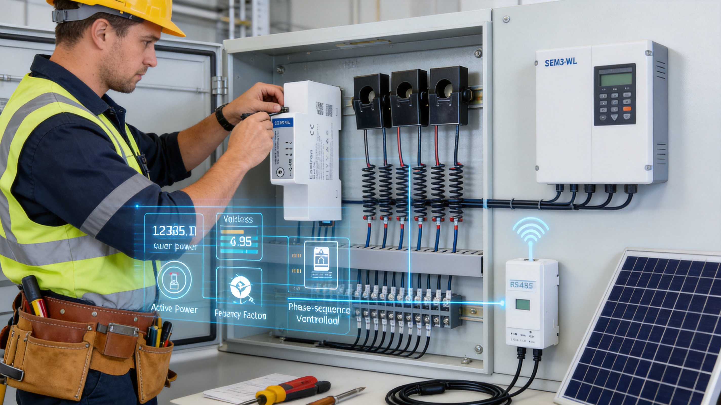
Before installation, the engineer should identify the supply arrangement, nominal voltage, frequency, maximum current, current-transformer ratios, measurement mode, communication method, and location of the measurement point. For solar PV systems, the relationship between the meter, inverter, grid connection point, and local loads should be clearly documented.
The meter should be installed on a suitable DIN rail inside an enclosure that provides appropriate protection and environmental conditions. The installation must follow applicable electrical codes and the manufacturer’s instructions. Isolation and safety procedures are essential, especially when current transformers are installed around energized conductors.
Each current transformer must be installed in the correct direction and assigned to the correct phase. Reversed or mismatched current transformers can cause negative power readings, incorrect import and export calculations, or phase-to-phase inconsistencies. The current-transformer ratio must correspond to the configuration entered into the meter or the connected monitoring system.
When the device is used in three-independent-single-phase mode, each sensor can be associated with a separate load and may use a different ratio. This capability should be recorded in the installation documentation so that future maintenance personnel understand which transformer belongs to which circuit.
After the voltage connections and current transformers are installed, the commissioning engineer should check phase sequence, phase association, voltage readings, current direction, and power-factor behavior. The phase-sequence warning provides an additional indication of wiring problems, but the complete set of readings should be reviewed before the system is placed into normal operation.
For RS485 communication, the installer should set the device address, baud rate, parity, stop bits, and communication format to match the master device. For Wi-Fi Modbus TCP, the network connection and addressing method should be configured according to the site’s network policy.
Communication should be tested by reading representative values such as voltage, current, active power, and cumulative energy. The system integrator should also confirm the register interpretation, floating-point format, byte order, scaling, and sign convention for imported and exported energy.
The selected Total or PV mode should be verified under real operating conditions. If the site is consuming electricity from the grid, the import indication should be checked. When solar generation exceeds local consumption, the export or PV balancing behavior should be reviewed. A short commissioning record containing expected and observed readings can help prevent later confusion.
The meter’s value increases when its data is integrated into a broader platform. A gateway or software system can collect readings at regular intervals, store historical values, display trends, generate alarms, and provide reports. Data can be organized by site, building, distribution board, inverter, production line, or individual load.
For zero-export control, the monitoring system should prioritize active power at the relevant grid connection point. For energy analysis, it may also collect reactive power, power factor, frequency, and phase-level values. Different sampling intervals may be used for control and reporting. Fast values can support control decisions, while longer-term averages can reduce storage requirements and make trends easier to interpret.
Alarm functions can be based on overcurrent, unusual voltage, low power factor, unexpected export, communication failure, or phase imbalance. The exact alarm logic belongs to the supervisory system, but the meter supplies the underlying measurements required to create these functions.
Cybersecurity should also be considered when using Wi-Fi. Network access should be limited to authorized devices, passwords should be managed securely, and the meter should be installed in accordance with the organization’s information-technology policies. Where the control system requires a dedicated physical network, RS485 may be preferred.
System designers benefit from a meter that supports several wiring arrangements, two measurement modes, and both wired and wireless communications. These features make it easier to standardize designs across residential, commercial, and industrial projects while retaining the flexibility required for different sites.
The compact form factor can simplify panel layouts, while the multi-parameter measurement capability reduces the need for separate power meters and energy counters. Designers can also select between a three-phase monitoring strategy and three independent single-phase channels according to the project’s priorities.
Installers can benefit from the included current transformers, spring or RJ terminals, DIN-rail mounting, and phase-sequence warning. These features are intended to reduce installation time and support faster troubleshooting. Wi-Fi connectivity can be particularly useful when a communication cable is difficult to route.
Facility managers receive a more complete view of energy performance. Instead of seeing only total consumption, they can examine power demand, phase loading, power factor, imported energy, exported energy, and reactive energy. This information can support maintenance planning, energy-saving measures, and evaluation of PV performance.
Energy-service providers can use the meter as part of a standardized monitoring package. Its communication options support different customer networks, while its flexible measurement modes allow the same product to be used for whole-building monitoring or selected loads. This can simplify procurement, training, and service support across multiple installations.
| Item | Specification |
|---|---|
| Supported systems | 1P2W, 3P3W, and 3P4W |
| Measurement type | RMS measurement including harmonics on three-phase AC systems |
| Nominal voltage | 3 × 230 V line-to-neutral / 400 V line-to-line |
| Working voltage range | 90–300 V AC line-to-neutral; 156–520 V AC line-to-line |
| Frequency range | 50/60 Hz |
| Active-energy accuracy | ±1 percent; Class B active energy |
| Reactive-energy accuracy | ±2 percent |
| Power accuracy | ±1 percent, stated IEC 61557-12 Class 1 reference |
| Voltage accuracy | ±0.5 percent |
| Frequency accuracy | ±0.2 percent |
| Power-factor accuracy | ±0.1 |
| Current accuracy | ±0.5 percent from 4–120 A; ±1 percent from 1–4 A; ±3 percent from 0.06–1 A |
| Measurement modes | Total mode and PV mode |
| Measurement arrangement | One three-phase meter or three independent single-phase meters |
| Current-transformer package | Three current transformers included |
| Wired communication | RS485, Modbus RTU |
| RS485 address range | 1–247 |
| RS485 transmission speed | 2400–115200 bps |
| RS485 transmission distance | Up to 1000 m under suitable installation conditions |
| Wireless communication | Wi-Fi, Modbus TCP |
| Wi-Fi standard | 802.11 b/g/n |
| Wi-Fi band | 2.4–2.5 GHz |
| Stated Wi-Fi range | Up to 30 m indoors and 50 m outdoors, depending on conditions |
| Mounting | DIN rail |
| Width | One modular width |
The SEM3-WL is particularly appropriate when a project requires multifunction measurement, bidirectional energy monitoring, PV balancing, and flexible communications in a compact enclosure. It is well suited to installations where the meter must connect to an inverter controller, energy gateway, building management system, or industrial automation network.
Engineers should confirm the required current range and select current transformers that match the conductors and expected load. They should also determine whether the application needs Total mode or PV mode, whether the system uses a three-phase or three-independent-single-phase arrangement, and whether Wi-Fi or RS485 is the preferred communication path.
For applications requiring legal metrology, revenue billing, or a specific national approval, the exact model certification and approval status must be checked against the project requirements. Monitoring and control applications may have different certification expectations from utility billing applications.
Environmental conditions should also be reviewed. Temperature, humidity, dust, vibration, electromagnetic interference, enclosure rating, and network availability can all influence installation performance. A suitable enclosure and properly designed electrical protection should be used for the site environment.
The meter supports 1P2W, 3P3W, and 3P4W systems. It is designed for nominal three-phase voltage of 3 × 230 V line-to-neutral or 400 V line-to-line, with a stated working range of 90–300 V AC line-to-neutral and 156–520 V AC line-to-line.
Yes. The meter provides four-quadrant measurement and supports bidirectional energy measurement. In Total mode, imported and exported energy are measured separately. In PV mode, imported and exported energy are balanced first according to the product’s stated operating method.
It can provide the electrical measurements required by a compatible zero-export control system. The meter supplies active-power and energy-flow information, while the inverter or external controller performs the export-limiting action. The complete system must be designed and commissioned for the specific inverter and grid requirements.
Yes. In single-phase mode, the meter can operate as three independent single-phase meters. Each channel can be associated with a separate load, and different current-transformer ratios can be configured for the three channels.
The product package includes three current transformers. The installer must still verify that the supplied transformers are suitable for the conductor size, expected current, installation arrangement, and project requirements.
The meter provides RS485 communication using Modbus RTU and Wi-Fi communication using Modbus TCP. RS485 supports configurable address, baud rate, parity, and stop-bit settings. Wi-Fi operates in the 2.4 GHz band and supports 802.11 b/g/n.
No. Wi-Fi can simplify retrofit installations and reduce communication cabling, but its performance depends on signal strength, building structure, interference, and network configuration. RS485 may be preferable for industrial environments, long cable runs, or systems requiring a dedicated wired network. Having both options allows the integrator to choose the appropriate method.
It measures voltage, current, frequency, active power, reactive power, apparent power, power factor, active energy, reactive energy, and related import and export values. It also provides maximum-demand information and four-quadrant measurement functions.
The stated active-power update rate is 50 milliseconds through RS485 and 100 milliseconds through Wi-Fi. Actual system response also depends on communication polling, controller processing, inverter response, and network conditions.
The warning helps identify an incorrect phase sequence during installation or commissioning. It can reduce troubleshooting time and help prevent incorrect interpretation of three-phase power and energy readings.
The meter is designed for energy monitoring and PV or zero-export applications. If it is to be used for revenue billing or another legally regulated purpose, the exact model’s approvals, accuracy class, installation requirements, and local regulations must be verified before selection.
The installer should check the supply type, voltage, phase sequence, current-transformer orientation, transformer ratios, phase association, measurement mode, communication settings, network connection, and the consistency of displayed values with expected load conditions.
The SEM3-WL brings together the core functions required by modern solar PV and energy-management projects: bidirectional energy measurement, multi-parameter monitoring, configurable measurement modes, Wi-Fi, RS485 Modbus RTU, Modbus TCP, external current transformers, fast active-power updates, and a compact DIN-rail form factor.
Its ability to operate as one three-phase meter or three independent single-phase meters gives it an advantage in applications with changing or mixed load structures. Its Total and PV modes provide a practical choice for detailed energy-flow reporting and photovoltaic balancing. The combination of Wi-Fi and RS485 communication enables both convenient retrofit installation and robust industrial integration.
The product’s value is supported by the manufacturer’s broader capabilities in electricity measurement, embedded software, communications, testing, quality management, and international technical support. Laboratory facilities for EMC, safety, accuracy, and environmental testing, together with ISO 9001 practices and continuing research and development, provide an engineering foundation for dependable metering products.
For installers and system designers, the meter offers a compact and adaptable method of obtaining the electrical data required for PV optimization, zero-export control, smart-building monitoring, industrial energy analysis, and distributed load management. When correctly selected, wired, configured, and integrated with suitable control equipment, it can serve as a central measurement component in a modern low-voltage energy system.
1. Product technical information for the SEM3-WL three-phase Wi-Fi multifunction solar PV and zero-export meter.
2. IEC 61557-12, Electrical safety in low-voltage distribution systems—Power metering and monitoring devices.
3. Modbus Organization, Modbus Application Protocol Specification.
4. Modbus Organization, Serial Line Implementation Guide.
5. IEEE 802.11 wireless local area network standards.
6. ISO 9001, Quality management systems—Requirements.
7. General principles for current-transformer installation, polarity identification, ratio selection, and energy-meter commissioning.
8. General guidance for grid-connected photovoltaic systems, self-consumption optimization, and export-limitation control.
Your email address will not be published. Required fields are marked *

We develop and produce high performance electricity meters, power analyzers, current sensors, communication modules and management systems.
Address:NO. 52, Dongjin Road, Nanhu, Jiaxing, Zhejiang, China
Copyright @ Eastron Electronic Co., Ltd. All rights reserved
