

 English
 Español
 Deutsch
 中文简体


Product Consultation
Your email address will not be published. Required fields are marked *
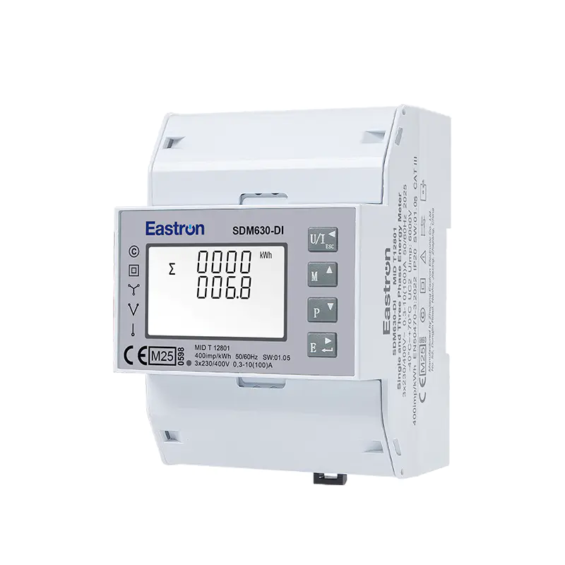
MID & UL Approved Three Phase Din Rail Type Multi-function Energy Meter for EV Charging Metering
Nov 24,2022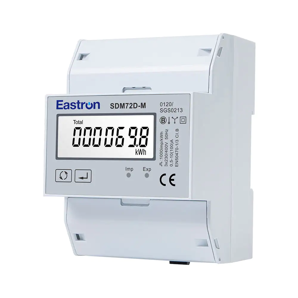
MID Din Rail Three Phase Multi-function EV Meter for EV Charging Metering
Aug 02,2022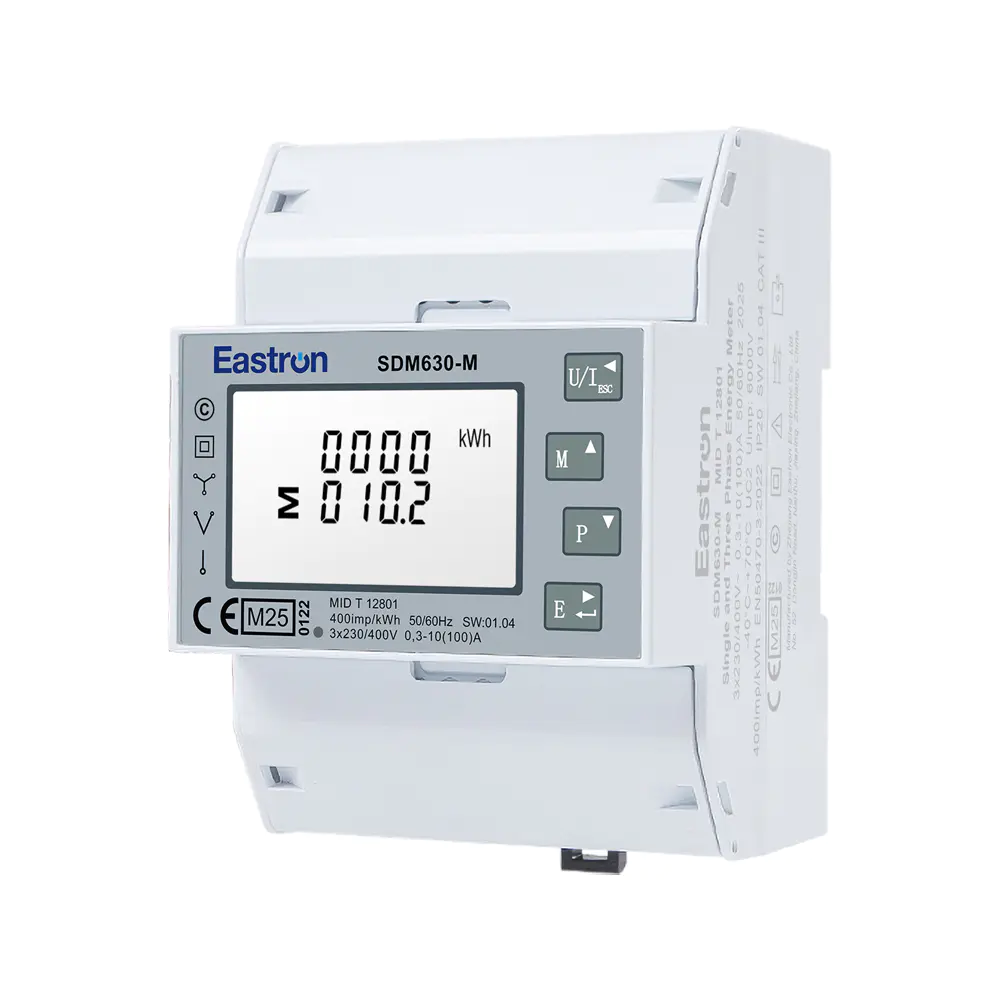
MID UL Certified Din Rail Three Phase Multi-function Energy Meter for EV Charging Metering
Aug 02,2022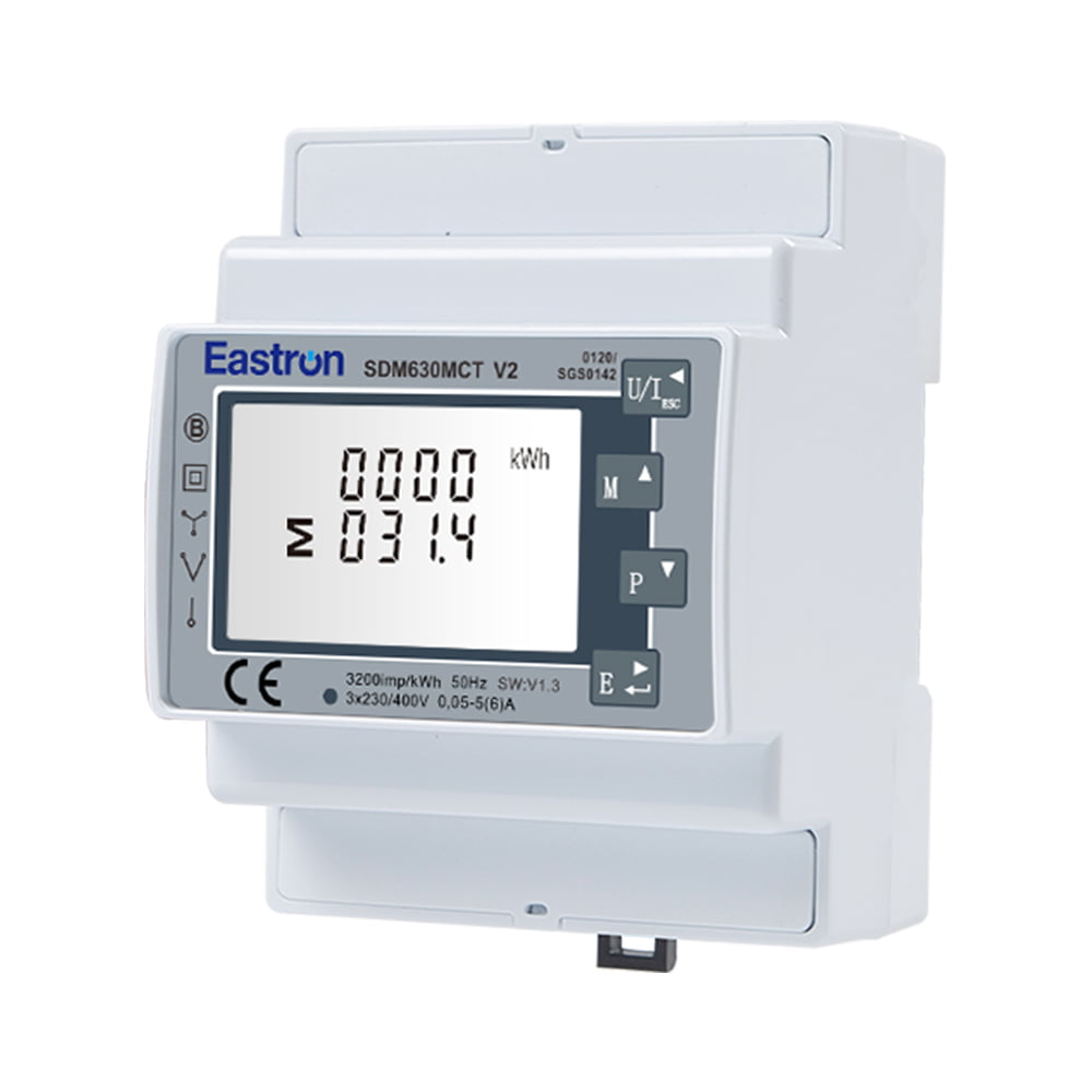
MID Approved CT Type Din Rail Three Phase Multi-function Solar PV /Zero Export Meter for PV Metering
Nov 24,2022
MID 3 Modules Din Rail Three Phase Multi-function Solar PV /Zero Export Meter for PV Metering
Aug 02,2022
MID Din Rail Three Phase Multi-function Solar PV /Zero Export Meter for PV Metering
Aug 02,2022Content

Modern electricity distribution systems require more than a basic energy counter. Operators need dependable measurements, clear local indication, flexible communications, rapid installation, and confidence that the instrument will support regulatory and commercial requirements. The MID DIN rail three-phase multifunction meter with PK96 panel adaption kit combines these needs in one compact solution for distribution boards, control panels, sub-metering installations, and commercial energy-management applications.
Based on the SDM630MCT series and the PK96 panel kit, this solution converts a DIN rail current-transformer meter into a practical panel-mounted instrument. It is designed for three-phase three-wire and three-phase four-wire systems, supports 1 A or 5 A current-transformer secondary inputs, and provides multifunction measurement, pulse outputs, and communication options. Depending on the selected meter variant, users can choose Modbus RTU, M-Bus, or LoRaWAN connectivity, as well as dual-power-source functionality on applicable models.
The result is a cost-effective metering platform that combines the installation flexibility of a DIN rail device with the visibility and front access expected from a panel meter. It is particularly useful where an existing enclosure has a 92 mm² cutout, where front access is important, or where several electrical parameters must be monitored through a single instrument.
Electrical distribution boards often serve as the operational center of a facility. They distribute power, protect circuits, and provide a convenient location for measuring consumption and electrical performance. However, a conventional DIN rail meter and a conventional panel meter are not always interchangeable in practical installations.
A DIN rail meter is normally easy to mount inside a cabinet, but its display may not be visible from the outside. A traditional panel meter provides direct visibility, yet replacing an existing unit can require additional wiring, a different cutout, or a more complicated mechanical installation. The PK96 panel adaption kit addresses this gap by providing a dedicated cradle for the SDM630MCT series.
The front-facing arrangement makes it easier for an operator to check voltage, current, power, energy, power factor, frequency, and related values without opening the distribution board. This can improve routine inspection and reduce the time required to identify abnormal operating conditions.
In addition, multifunction measurement can reduce the number of separate instruments required in a panel. Instead of installing individual meters for current, voltage, active power, reactive power, apparent power, frequency, and energy, one integrated device can provide these measurements through its display and communication interfaces.
For commercial buildings, industrial plants, renewable-energy systems, data rooms, workshops, and infrastructure projects, this consolidation can simplify panel design. It may also reduce wiring complexity, occupy less internal space, and make future integration with energy-management software more straightforward.
The product consists of two coordinated elements: an SDM630MCT-series multifunction electricity meter and a PK96 panel adaption kit. The meter is installed in the cradle, while the kit provides the panel-mounted form factor and access arrangement.
The system is suitable for three-phase three-wire and three-phase four-wire networks. It measures RMS values, including harmonics, on three-phase AC systems. Current is measured through external current transformers, with selectable 1 A or 5 A CT secondary input compatibility. The CT primary ratio can be configured from 1 A to 9999 A, allowing the meter to be adapted to a wide range of electrical installations.
The rated voltage is specified as 230 V line-to-neutral or 120 V line-to-neutral, with an operational range of 80% to 120% of the rated voltage. The minimum current is 0.25 A, while the starting current is 20 mA. These characteristics enable the meter to monitor both normal operating loads and lower-load conditions within appropriately designed systems.
The meter provides two pulse outputs in relevant configurations. Pulse outputs can be used to transmit energy accumulation information to external counters, building-management systems, data loggers, or other supervisory equipment. In addition, the standard communication arrangement includes RS485 with Modbus RTU, enabling connection to a broad range of industrial controllers and monitoring platforms.
Other versions expand the communication choices. The SDM630MCT-Mbus model supports M-Bus communication according to EN 13757. The SDM630MCT-LoRa model supports LoRaWAN communication, with frequency options including EU868, AS923, AU915, and US915 variants. Models with the dual-power-source option provide an additional 2T function for applications that require two power sources.
One of the most important mechanical benefits is compatibility with a 92 mm² panel cutout. This allows the solution to fit a commonly required panel opening while preserving a clean front-panel appearance. For retrofit work, this can be more convenient than redesigning the enclosure or fabricating a new mounting plate.
A correctly matched cutout also helps reduce the risk of gaps, misalignment, and unnecessary mechanical modification. Installers can focus on securing the meter, completing the electrical connections, and commissioning the measurement system rather than creating a custom housing solution.
The detachable fascia is designed to provide access to screw terminals from the front. This feature can be valuable in compact switchboards where internal access is restricted after the panel has been installed. It also supports more efficient maintenance, because technicians may be able to inspect or adjust connections without removing the entire meter from the enclosure.
Front access is especially helpful during commissioning. A technician can install the meter into the panel, connect the CT circuits and voltage references, and verify the wiring while working from the accessible side of the equipment. The arrangement is intended to make installation quicker and more convenient than solutions that require repeated removal of the complete instrument.
The PK96 cradle has been designed for quick installation. Its purpose is not simply to make the meter look like a panel instrument; it provides a practical mechanical interface between a DIN rail meter and a panel opening. This makes it suitable for distribution boards and other applications where installation time, repeatability, and a tidy result are important.
A fast installation process can create value across the project lifecycle. Panel builders can standardize their designs, electrical contractors can reduce on-site labor, and facility operators can shorten downtime during replacement or expansion work. These advantages are particularly relevant where multiple panels use the same metering architecture.
The PK96 panel kit can work with the SDM630MCT series. This gives users flexibility when selecting communications and application features. A project can use a Modbus version for a PLC-based control system, an M-Bus version for a building energy network, or a LoRaWAN version where wireless data transmission is preferred.
This approach can also simplify product standardization. Instead of designing a different panel layout for every communication requirement, a common panel adaptation concept can be used across several meter variants. The electrical and communications design may still differ, but the physical mounting approach remains consistent.
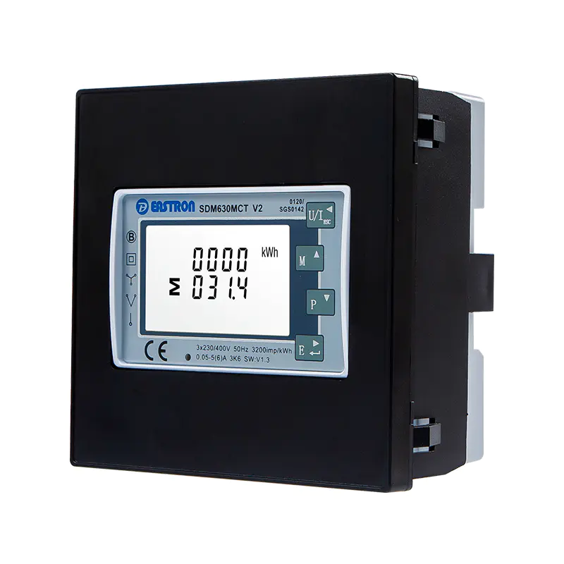
MID Din Rail Three Phase Multi-function Meter with PK96 Panel Adaption Kit
The meter is intended for RMS measurement, including harmonics, on three-phase AC networks. This makes it more informative than a simple meter that reports only a limited selection of fundamental electrical values. Harmonic-inclusive RMS measurement is relevant in modern installations containing variable-speed drives, switching power supplies, LED lighting, uninterruptible power supplies, electronic chargers, and other nonlinear loads.
The measurement functions include voltage, current, frequency, power factor, active power, reactive power, apparent power, active energy, and reactive energy. These values allow users to examine both consumption and operating conditions.
Voltage measurement provides an immediate view of the electrical supply at the monitored point. Comparing phase-to-neutral values and observing voltage behavior over time can help operators identify supply imbalance, voltage variation, or wiring issues. The specified voltage measurement accuracy is ±0.5%.
Current is measured through external CTs. This arrangement allows the meter to monitor circuits with currents much higher than the direct input capacity of a compact electronic instrument. By selecting suitable CT primary ratings and configuring the meter to match the installed ratio, the same meter family can be used in small commercial panels and larger distribution systems.
The current measurement accuracy is specified as ±0.5%. Correct CT selection, polarity, phase association, and wiring remain essential to achieving the expected system performance. The meter’s ability to accept 1 A or 5 A CT secondary signals gives panel designers additional flexibility when choosing protection and measurement transformers.
Frequency measurement is specified at ±0.2% accuracy. Frequency data can help confirm the stability of the supply and may provide useful context when analyzing equipment behavior. Power factor measurement, specified at ±1%, helps users understand how effectively a load uses supplied electrical power.
Monitoring power factor can support corrective-action decisions. For example, a facility may use the information to investigate inductive loads, assess capacitor-bank performance, or identify changes in production equipment. The meter does not replace a complete power-quality study, but it provides a practical operational indicator.
Active power represents the portion of power associated with useful work and heat production. Reactive power reflects the exchange of energy between the electrical system and reactive components such as motors and transformers. Apparent power combines the active and reactive components and is important when evaluating transformer, cable, and switchgear loading.
Each of these power measurements is specified at ±1% accuracy. Their combined availability helps operators distinguish between increased real consumption and increased electrical loading caused by reactive demand or poor power factor.
Active energy performance is identified as Class 0.5S according to IEC 62053-22 and Class 1.0 according to IEC 62053-21. The product information also identifies Class B and Class C performance under EN 50470-3:2022. Reactive energy is specified as Class 2 according to IEC 62053-23.
These classifications are important for users who need a meter suitable for structured energy accounting, allocation, or approved measurement applications. The exact suitability of any installation should always be confirmed against the applicable national regulations, approval documentation, installation conditions, and project requirements.
Energy data becomes more valuable when it can be collected automatically. Manual readings may be useful for basic checks, but they provide limited historical information and require personnel time. The communication options of the meter support integration into larger monitoring and management systems.
The RS485 interface with Modbus RTU is a practical choice for industrial and building automation. The communication address range is 1 to 247. Transmission speeds range from 1200 bps to 38400 bps, with none as the default parity option and odd or even parity also available. Stop-bit settings can be configured as one or two, and the stated response time is less than 100 milliseconds.
The maximum transmission distance is specified as 1000 meters. Actual performance depends on cable type, network topology, termination, grounding, electromagnetic conditions, baud rate, and the installation environment. Within a correctly designed RS485 network, the meter can provide data to a PLC, supervisory control system, energy-management platform, gateway, or data acquisition unit.
Modbus RTU is widely used because it is straightforward to implement and supported by many controllers. This can reduce integration risk compared with proprietary communication systems. It also allows the meter to participate in a multi-device network in which several meters report to a central system.
The SDM630MCT-Mbus version supports M-Bus communication according to EN 13757-3. M-Bus is widely associated with utility and building metering applications. The stated address range is 1 to 250, with transmission distances up to 1000 meters and baud rates from 300 bps to 9600 bps.
Parity may be set to none, odd, or even, and one or two stop bits are available. M-Bus can be an appropriate option when a project already uses M-Bus meters and a compatible concentrator or gateway. It can help maintain a consistent communications architecture across electricity, heat, water, and other metering points where the overall system supports those devices.
The SDM630MCT-LoRa version provides LoRaWAN communication. Wireless communication can be useful in buildings or distributed sites where running new communication cables would be costly or disruptive. The stated regional frequency options include EU868, AS923, AU915, and US915, among others.
LoRaWAN deployment requires suitable network coverage, gateway planning, device provisioning, security configuration, and compliance with regional radio requirements. When those conditions are satisfied, wireless energy data can support remote monitoring of panels that are separated from a central control room or located in areas where wired communication is difficult.
Two pulse outputs are available on the stated configurations. Pulse outputs provide a simple and widely understood method for transmitting energy accumulation to an external device. They can be connected to counters, pulse collectors, programmable controllers, or building-management equipment that supports energy pulses.
Pulse output is also useful as a secondary integration method. A site may use Modbus for detailed real-time data while using a pulse channel for an independent energy total or a legacy monitoring system. The choice depends on the project’s data requirements and the capabilities of the receiving equipment.
The product is particularly suited to distribution boards. Its panel-mounted presentation makes the measurement point visible, while the CT input arrangement allows monitoring of substantial feeder currents without routing high-current conductors through the meter itself.
In a distribution board, the meter can be used to observe the total incoming supply, a major outgoing feeder, a production area, a tenant circuit, or a dedicated mechanical-services load. The exact location depends on the measurement objective and the electrical design.
Commercial buildings often need to divide energy use among tenants, floors, departments, or major services. Active and reactive energy readings can support internal allocation, while communication interfaces can transmit data to a building-management or energy-management platform.
Panel visibility is beneficial for facility personnel who need to verify readings locally. Remote communications are beneficial for long-term analysis, reporting, alarms, and benchmarking. The combination allows the same meter to support both day-to-day operation and broader energy-improvement programs.
Manufacturing plants contain motors, drives, heating equipment, compressors, pumps, and process machinery with changing loads. Monitoring voltage, current, power factor, active power, reactive power, and apparent power can help maintenance and engineering teams understand how individual production areas behave.
Because the meter supports CT secondary inputs of 1 A or 5 A and allows a broad CT primary configuration range, it can be adapted to different feeder sizes. Engineers must still select CTs with appropriate ratio, burden, accuracy class, insulation, and installation method.
Solar power systems, energy-storage installations, and other distributed-energy projects may require measurement at the grid connection point, inverter output, auxiliary supply, or individual distribution section. A three-phase multifunction meter can provide information about exported or imported energy, power flow, and electrical operating conditions.
Project designers should confirm the required direction-of-energy conventions, tariff functions, communications protocol, and regulatory requirements before choosing the exact variant. Where wireless reporting is needed, a LoRaWAN model may be considered; where a local controller is present, Modbus may be more appropriate.
Infrastructure sites may include pumping stations, telecommunications facilities, transport systems, remote utility rooms, and service buildings. These locations can benefit from automatic reporting because routine physical inspections may be infrequent or expensive.
Communication selection is central to these applications. RS485 can provide a robust wired connection inside a facility, M-Bus can fit a metering network, and LoRaWAN can extend visibility where appropriate wireless infrastructure is available.
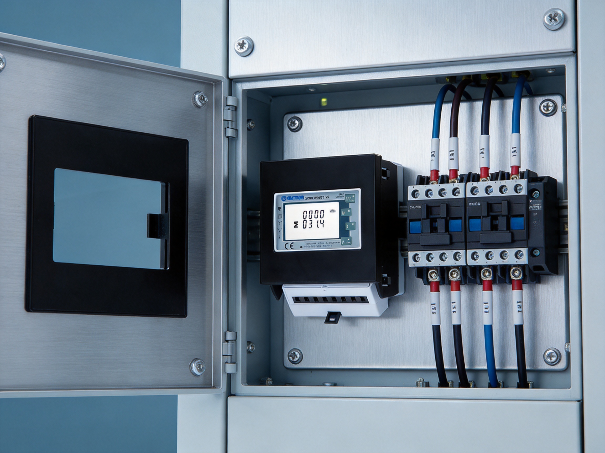
Product comparisons should be based on the actual project requirements, but this solution offers several practical advantages over common alternatives.
A basic energy meter may report only active energy. That can be sufficient for a simple consumption total, but it provides limited information about voltage quality, load behavior, reactive demand, or apparent loading. The multifunction design supplies a broader set of measurements in one device.
This broader data set can reduce the need for separate instruments. It can also help users move from simple billing or recording toward active energy management. When a facility experiences rising demand or unexpected consumption, additional electrical parameters can provide useful diagnostic context.
Installing separate voltage, current, power, frequency, and energy instruments may create a more complicated panel. Each device can require its own mounting position, wiring, configuration, and maintenance process. An integrated multifunction meter can reduce panel complexity and provide a more consistent user interface.
Integration does not eliminate the need for protective devices, appropriate CTs, fuses, isolation, or engineering review. It does, however, provide a compact measurement core around which the rest of the panel can be designed.
A DIN rail-only meter can be efficient inside a cabinet, but the display may be difficult to read without opening the enclosure. The PK96 kit provides a panel-facing arrangement and is compatible with a 92 mm² cutout. This can improve local access and make the instrument more suitable for visible front-panel operation.
Without a dedicated kit, a panel builder may need to design a bracket, modify the enclosure, or use a custom plate to adapt a DIN rail instrument to a panel opening. Such work can increase design time and introduce variation between installations. The PK96 solution provides a standardized adaptation concept intended for quick installation.
Modbus RTU, M-Bus, pulse output, and LoRaWAN are established communication or integration choices. Their availability can make the meter easier to incorporate into existing systems than a device that depends exclusively on a proprietary protocol. Project teams can select the communication method that best matches their automation, building-management, or remote-monitoring architecture.
Multi-tariff functionality is available on the relevant meter configurations. Multi-tariff measurement can be useful where energy costs vary according to time periods, operating schedules, or contractual arrangements. It may also help organizations compare consumption during production hours, standby periods, peak intervals, and off-peak intervals.
Tariff configuration should be coordinated with the utility arrangement and the project’s energy-accounting rules. The meter provides a measurement platform, but the accuracy of financial allocation also depends on correct CT installation, meter configuration, data collection, tariff programming, and validation procedures.
When connected to an energy-management system, tariff data can support reports that identify when energy is being consumed and how much it costs under the applicable schedule. This can help facility operators evaluate load shifting, equipment scheduling, demand reduction, and operational efficiency measures.
The product is supported by the capabilities of Eastron Electronic Co., Ltd., a manufacturer focused on electricity meters and energy measurement solutions. The company develops and produces electricity meters, power analyzers, current sensors, communication modules, and management systems. This product breadth is relevant because modern metering is not limited to a standalone display; it increasingly involves sensing, communications, data management, and system integration.
The company maintains development teams in China and the United Kingdom and continues to invest in new electricity-metering technologies and products. Cooperation with universities and institutions contributes to access to technical knowledge and supports ongoing product development.
For customers, an active research and development capability can be important when product requirements evolve. Energy systems are becoming more distributed, connected, and data-driven. Metering products must therefore address not only measurement accuracy but also communication compatibility, system integration, installation flexibility, and changing regulatory expectations.
The company has established a professional laboratory capable of performing electromagnetic compatibility, low-voltage directive, accuracy, and environmental tests. These tests are associated with IEC, EN, GB, and UL-related requirements, depending on the product and applicable market.
In-house testing can support more efficient development feedback. Engineers can evaluate prototypes, investigate measurement behavior, verify communication performance, and examine environmental or electromagnetic conditions before products reach the market. Laboratory capability does not replace independent approvals where they are required, but it can strengthen internal quality control and design verification.
The company follows the ISO 9001 quality-management system. A structured quality system can help organize design control, supplier management, production procedures, inspection, corrective action, documentation, and customer support.
Consistent manufacturing is especially important for electricity meters because the product must combine precision electronics, measurement inputs, display functions, communications, and mechanical components. Quality management helps ensure that these elements are controlled throughout the product lifecycle rather than checked only at the final stage.
The product information identifies MID approval and notes that production is approved by SGS according to MID standards. MID-related metering applications require careful attention to design, testing, production control, documentation, and conformity processes. The exact legal use of a particular meter depends on its model, marking, certification, installation, and the regulations applicable in the target market.
For buyers, the availability of MID-oriented products can simplify the initial selection process when a project requires a meter intended for regulated or commercial measurement. Procurement teams should still request and review the current declaration, certificate, marking information, and model-specific documentation before placing an order.
The company holds patented technologies in software, embedded software, and hardware. This indicates a broad engineering approach that addresses several layers of a modern metering product. Hardware design affects sensing and reliability, embedded software controls measurement and display behavior, and communication software supports data exchange with external systems.
The combination of these capabilities is valuable in products such as the SDM630MCT series, where electrical accuracy, configurable parameters, user operation, and communications must work together as a coherent system.

Although the PK96 kit is designed for quick installation, correct electrical installation remains essential. Work should be performed by qualified personnel in accordance with local electrical codes, the meter manual, and the requirements of the distribution system.
The CT primary ratio must be selected according to the expected circuit current and the required measurement range. The meter supports CT primary settings from 1 A to 9999 A and accepts 1 A or 5 A secondary input. The configured ratio must match the installed transformer.
CT polarity and phase identification are equally important. The primary direction, secondary terminals, and phase association should be verified before energization. Incorrect polarity can cause inaccurate power or energy direction, while incorrect phase association can distort total power and power factor calculations.
The selected three-phase wiring arrangement must match the network: three-phase three-wire or three-phase four-wire. Rated voltage and operational voltage should be checked against the actual system. Voltage references must be connected according to the wiring diagram, with suitable isolation and protection provisions.
For RS485 installations, network topology, cable shielding, termination, address allocation, baud rate, parity, and stop-bit settings should be planned before commissioning. Each device should have a unique address. Long cable runs and electrically noisy environments may require careful routing and grounding practices.
For M-Bus systems, the master device, bus loading, address plan, and cable arrangement should be confirmed. For LoRaWAN installations, regional frequency, gateway coverage, device credentials, and network security should be addressed during commissioning.
The panel cutout should be prepared accurately to the required 92 mm² size. The PK96 kit should be mounted securely, and the detachable fascia should be handled carefully during installation and service. The panel should provide adequate clearance for wiring, ventilation, protection, and safe access.
After installation, the operator should verify the meter model, CT ratio, wiring mode, voltage configuration, communications settings, and tariff parameters where applicable. A comparison with a trusted reference instrument or a known load can help confirm the installation.
Commissioning should include a check of phase readings, total active power, power factor, energy accumulation, pulse output behavior, and communications response. Documenting these initial values provides a useful baseline for future maintenance and troubleshooting.
Reliable measurement depends on both product design and installation quality. The meter should be used within its specified electrical and environmental conditions. Enclosures should protect the equipment from excessive moisture, dust, vibration, heat, and mechanical impact.
Periodic inspection can include checking terminal tightness according to approved procedures, reviewing communications status, comparing readings with expected operating conditions, and examining whether CTs and voltage connections remain correctly identified. Any maintenance on the meter or associated circuits must follow safe isolation practices.
Remote data collection can support condition awareness. Sudden changes in current, power factor, voltage, or energy consumption may indicate a change in equipment operation or a measurement issue. Historical data can also help distinguish a temporary event from a gradual change in facility performance.
The panel-mounted display remains valuable even in connected installations. A local reading can provide a quick cross-check when a remote system reports unexpected data. This combination of local and remote access is one of the practical strengths of a visible multifunction meter.
Choosing the correct variant requires more than selecting the desired appearance. Buyers should identify the network type, voltage, CT secondary current, CT primary range, communication method, tariff requirements, pulse-output requirements, and any dual-power-source needs.
| Selection Item | Available or Relevant Option | Project Consideration |
|---|---|---|
| System wiring | Three-phase three-wire or three-phase four-wire | Match the meter configuration to the electrical network. |
| CT secondary | 1 A or 5 A | Match the meter to the installed current transformer. |
| CT primary setting | 1 A to 9999 A | Enter the correct transformer ratio for accurate readings. |
| Rated voltage | 230 V line-to-neutral or 120 V line-to-neutral | Confirm the voltage reference and system compatibility. |
| Mounting | DIN rail meter with PK96 panel adaption kit | Check the panel cutout and available internal clearance. |
| Wired communication | RS485 Modbus RTU | Suitable for PLC, SCADA, gateway, and energy-management integration. |
| Metering network | M-Bus EN 13757 | Consider when an M-Bus master or concentrator is already used. |
| Wireless communication | LoRaWAN | Confirm regional frequency, gateway coverage, and network provisioning. |
| Pulse interface | Two pulse outputs on applicable configurations | Useful for counters, data loggers, and legacy systems. |
| Dual-power-source function | Available on applicable 2T variants | Review the requirement for two power sources before ordering. |
| Tariff functionality | Multi-tariff options available | Coordinate with utility schedules and energy-accounting rules. |
Procurement teams should request the latest technical datasheet, wiring diagram, user manual, approval documentation, and communication register information for the exact model. Model suffixes can identify important differences, so the complete product designation should be included in purchase documents.
Panel builders benefit from a standardized approach to mechanical adaptation. The PK96 kit provides a defined mounting concept for a 92 mm² cutout, while the SDM630MCT series offers multiple communication and functional variants. This can support repeatable panel designs across different projects.
System integrators benefit from established protocols and several data-access methods. A Modbus version can be connected to a controller or gateway, an M-Bus version can join a metering network, and a LoRaWAN version can serve a distributed wireless architecture. Pulse outputs provide another option for systems with simple counting requirements.
Facility owners benefit from a combination of local visibility and digital integration. The meter can be read at the panel during inspection while also sending data to a central platform for reports and analysis. This dual approach can improve operational awareness without requiring a separate local display instrument.
Maintenance teams benefit from front-facing access and a broad measurement set. When an electrical issue is reported, technicians can inspect several parameters from one device before deciding whether further testing is required. This can make first-line diagnosis more efficient.
The meter can support energy-management activities in several ways. First, it provides a consistent measurement point for energy accounting. Second, it supplies electrical parameters that help explain energy behavior. Third, it can communicate data automatically to software systems. Fourth, its panel-mounted format preserves convenient local access.
Energy managers can use active-energy values to establish baselines and compare consumption by area or process. Power readings can help identify periods of high demand. Reactive-power and power-factor data can assist with evaluating compensation systems and inductive loads. Apparent-power readings can provide context for equipment loading and capacity planning.
Historical data may reveal schedules that are not being followed, equipment that remains energized during idle periods, or gradual increases associated with aging machinery. The meter alone does not create savings, but accurate and accessible information supports better decisions.
The PK96 kit adapts an SDM630MCT-series DIN rail meter for panel-mounted use. It is designed to fit a 92 mm² cutout and provide a practical front-facing installation arrangement.
Yes. The product information identifies support for three-phase three-wire and three-phase four-wire systems. The meter must be configured and wired according to the actual network type.
No. The meter uses external current transformers. It accepts 1 A or 5 A CT secondary signals, while the CT primary setting can be configured from 1 A to 9999 A.
The meter can measure voltage, current, frequency, power factor, active power, reactive power, apparent power, active energy, and reactive energy. It performs RMS measurement including harmonics on three-phase AC systems.
Depending on the selected model, options include RS485 Modbus RTU, M-Bus EN 13757, and LoRaWAN. The applicable models also provide two pulse outputs, and certain variants include a dual-power-source function.
Yes. Modbus, M-Bus, and LoRaWAN versions can transmit data to compatible automation, metering, gateway, or energy-management systems. The communication method should be selected according to the project infrastructure.
The detachable fascia provides access to screw terminals from the front. This can simplify installation and maintenance in panels where internal access is limited.
The product is described as an MID-approved multifunction panel-mounted solution. Buyers should confirm the exact model certification, marking, installation conditions, and legal requirements for the intended country and application.
Active energy is identified as Class 0.5S under IEC 62053-22 and Class 1.0 under IEC 62053-21. The product information also identifies Class B and Class C under EN 50470-3:2022.
Users should confirm the network wiring, voltage, CT secondary rating, CT primary ratio, communication protocol, panel cutout, tariff requirements, pulse-output needs, and any requirement for dual power sources.
No. The meter is a measurement and communication device. Protective equipment, isolation, fuses, circuit breakers, CT protection arrangements, and other safety components must be designed separately by qualified professionals.
LoRaWAN availability depends on the selected model and regional frequency plan. The stated options include EU868, AS923, AU915, and US915, among others. Regional compliance and network coverage must be confirmed before deployment.
The MID DIN rail three-phase multifunction meter with PK96 panel adaption kit provides a practical answer to a common electrical-design challenge: how to combine compact DIN rail metering with visible, accessible, panel-mounted operation.
Its strengths include three-phase three-wire and four-wire compatibility, 1 A and 5 A CT inputs, configurable CT primary ratios, multifunction electrical measurement, MID-oriented energy accuracy, pulse outputs, and several communication choices. The PK96 kit adds a 92 mm² panel fit, detachable fascia, front screw-terminal access, and a quick installation concept.
Compared with basic single-function meters, it supplies more operational information. Compared with multiple separate instruments, it can simplify panel design. Compared with a DIN rail-only installation, it provides improved front-panel visibility. Compared with proprietary communication-only devices, its Modbus, M-Bus, pulse, and LoRaWAN options support broader integration planning.
These product characteristics are supported by the manufacturer’s investment in research and development, professional laboratory testing, ISO 9001 quality management, patent development, and MID-related production capability. Together, the product design and manufacturing foundation make this solution suitable for electricity distribution, commercial metering, industrial monitoring, building energy management, and connected infrastructure applications.
Successful deployment still depends on correct CT selection, accurate wiring, suitable panel preparation, appropriate communication design, and compliance with local regulations. When those requirements are properly addressed, the meter can provide a durable foundation for accurate measurement, convenient local operation, and scalable energy-data management.
IEC 62053-21, Electricity Metering Equipment: Particular Requirements for Static Meters for AC Active Energy.
IEC 62053-22, Electricity Metering Equipment: Particular Requirements for Static Meters for AC Active Energy, Classes 0.1S and 0.2S.
IEC 62053-23, Electricity Metering Equipment: Particular Requirements for Static Meters for Reactive Energy.
EN 50470-3:2022, Electricity Metering Equipment: Particular Requirements for Static Meters for AC Active Energy.
EN 13757-3, Communication Systems for Meters and Remote Reading of Meters: Application Protocols.
ISO 9001, Quality Management Systems: Requirements.
Manufacturer technical information for the SDM630MCT series three-phase multifunction meters and PK96 panel adaption kit.
Your email address will not be published. Required fields are marked *

We develop and produce high performance electricity meters, power analyzers, current sensors, communication modules and management systems.
Address:NO. 52, Dongjin Road, Nanhu, Jiaxing, Zhejiang, China
Copyright @ Eastron Electronic Co., Ltd. All rights reserved
