

 English
 Español
 Deutsch
 中文简体


Product Consultation
Your email address will not be published. Required fields are marked *
MID/ UL Approved Single Phase Din Rail Type Multi-function Energy Meter for EV Charging Metering
Nov 24,2022
MID Din Rail Type Single Phase Multi-function Energy Meter for EV Charging Metering
Jul 26,2022
MID Approved Single Phase Energy Meter for EV Charging Metering
Nov 24,2022
CT Connection Single Phase Din Rail Wifi Energy Meter for PV Metering
May 30,2025
MID/UL CT Type Din Rail Three Phase Multi-function Energy Meter for EV Charging Metering
Nov 24,2022
MID & UL Approved Three Phase Din Rail Type Multi-function Energy Meter for EV Charging Metering
Nov 24,2022Content
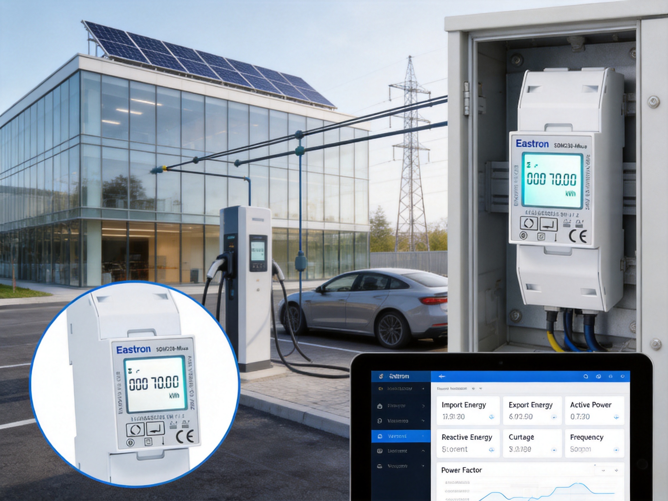
Accurate energy measurement is essential for modern electrical installations. Residential buildings, commercial facilities, industrial equipment, solar photovoltaic systems, electric vehicle charging stations and utility networks all require dependable data about how electricity is being consumed and generated. A suitable meter must do more than display kilowatt-hours. It should provide stable measurement, support remote communication, simplify installation, fit neatly into distribution equipment and operate reliably for many years.
The M-Bus DIN-rail multifunctional single-phase ETL energy meter is designed to meet these requirements in a compact two-module format. Based on a 1P2W single-phase configuration, the meter provides direct measurement for loads up to 65 A while monitoring active energy, reactive energy, voltage, current, power, power factor, frequency and demand-related values. Its integrated M-Bus interface and dual pulse outputs allow measured information to be transferred to building management systems, data concentrators, energy dashboards and other monitoring platforms.
With a rated current of 10 A, a maximum current of 65 A and an operating voltage range of 100 to 240 V, the meter can serve a broad range of single-phase applications. It is particularly useful where installation space is limited but several electrical parameters must be monitored from one device. Its DIN-rail housing supports efficient panel integration, while the backlit LCD provides local access to measurement data during commissioning, maintenance and routine inspection.
This article explains the meter’s operating capabilities, communication functions, measurement performance, installation advantages, application value and manufacturing strengths. It also examines why a compact multifunctional meter with direct connection and M-Bus communication can be a practical alternative to more complicated systems that require separate current transformers, multiple measuring instruments or additional communication converters.
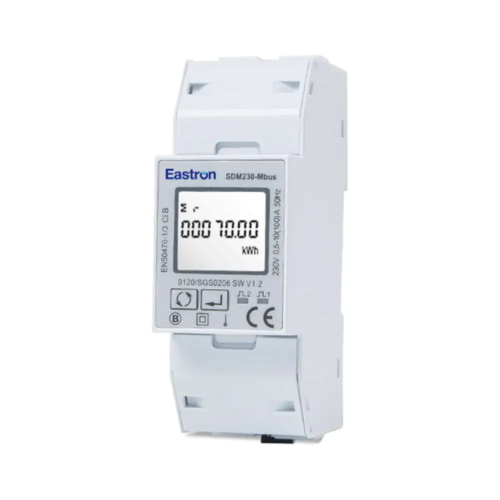
Mbus Din Rail Multi-functional Single Phase ETL Energy Meter
The meter is a single-phase, two-wire energy measuring device intended for installation on a standard DIN rail. Its 1P2W configuration is suitable for single-phase AC systems with line and neutral conductors. The meter measures the electrical characteristics of the connected circuit through a direct connection, avoiding the need for external current transformers in installations within its rated current range.
The device is available in several related configurations within the same product family. These configurations may include a pulse-only version, an RS485 Modbus version, an M-Bus version, a dual-tariff version and a model with a digital input. The M-Bus version is the focus of this article. It combines two pulse outputs with an M-Bus communication port complying with EN 13757 communication requirements.
The meter is intended for applications where electrical data must be viewed locally and collected remotely. The LCD presents measured values directly on the front of the unit, while the communication interface allows information to be transmitted to a supervisory system. This combination supports both manual operation and automated energy management.
The product’s principal functions include:
• Measurement of active and reactive energy.
• Measurement of voltage, current, active power, power factor and frequency.
• Support for bidirectional energy measurement.
• Two pulse outputs for import and export energy applications.
• M-Bus communication according to EN 13757-3.
• Direct connection for loads up to 65 A.
• Backlit LCD for local reading.
• DIN-rail installation in a two-module, 36 mm-wide enclosure.
• MID approval and ETL listing as specified for the product.
These functions make the meter more versatile than a basic kWh counter. Instead of reporting only accumulated energy, it can provide a broader view of the electrical installation and support more informed operational decisions.
Space inside electrical distribution boards is increasingly valuable. Modern panels may contain protective devices, contactors, residual-current devices, surge protection, communication equipment and control modules. A meter that occupies excessive space can increase panel size, installation cost and wiring complexity.
The compact two-module housing has a width of approximately 36 mm. This allows the meter to be installed alongside conventional DIN-rail equipment without requiring a separate enclosure. Its form factor is suitable for residential distribution boards, sub-panels, control cabinets, metering compartments and compact energy management panels.
A narrow housing also helps system designers create more organized electrical assemblies. When meters, circuit protection devices and communication modules are arranged on one rail, wiring paths can be shorter and maintenance access can be improved. The result is a cleaner installation that is easier to inspect and document.
The DIN-rail mounting method is widely understood by electrical contractors and panel builders. It avoids custom mounting brackets and reduces the time required to secure the unit. The front-facing display and terminals are accessible after installation, helping technicians perform commissioning and verification without removing the meter from the rail.
Compared with a larger multifunction power analyzer, the compact meter may be easier to install in locations where only one single-phase circuit must be monitored. Compared with a basic plug-in energy monitor, it offers a more permanent and professional installation method. This combination of compactness and functionality is one of its principal advantages.
The meter supports a maximum direct current of 65 A. This means that many residential, commercial and light industrial circuits can be connected without external current transformers. Direct connection simplifies the measurement circuit because the load conductors pass through the meter’s current terminals rather than through separate sensing transformers.
Eliminating external current transformers can provide several practical benefits. It reduces the number of components in the panel, decreases wiring requirements and removes the need to select, mount and maintain additional CTs. It also avoids costs associated with CT accessories, shorting terminals, secondary wiring and transformer installation.
Direct measurement can be especially useful in apartment submeters, tenant billing systems, small commercial buildings, workshop circuits, heat pump circuits, small photovoltaic systems and electric vehicle charging installations. In these applications, a 65 A capacity often covers the expected load while keeping the metering assembly compact.
External CTs remain useful for higher-current circuits, but they introduce additional considerations. The transformer ratio must match the application, the secondary circuit must be wired correctly and the installation must account for polarity and burden requirements. A direct-connected meter avoids these particular issues for circuits within its specified current range.
The stated electrical input characteristics include a 10 A rated current, a 65 A maximum current, a 0.5 A minimum current and a 40 mA starting current. These values provide the installer with a clear framework for selecting the meter for a particular circuit. Correct sizing remains important, and the installation should always comply with applicable electrical regulations, conductor ratings and protection requirements.
A single measurement value rarely provides enough information to understand an electrical system. Total kilowatt-hours may show how much energy has been used, but they do not reveal whether high consumption is caused by increased current, low power factor, voltage variation or changes in operating conditions. Multifunction measurement provides a more complete picture.
The meter measures active energy, reactive energy, current, voltage, power, power factor and frequency. It can also provide demand-related information, including dmd values where configured and supported. These measurements allow facility personnel to review both energy consumption and the conditions under which that consumption occurs.
Active energy is the primary quantity used for many energy monitoring and billing applications. Reactive energy is useful for evaluating inductive or capacitive behavior, especially in commercial and industrial installations. Current indicates the loading of the circuit, while voltage helps identify supply conditions. Active power shows the instantaneous rate of energy use, and power factor indicates how effectively electrical power is being utilized.
Frequency measurement provides an additional indication of supply stability. Although frequency is generally controlled by the utility network, monitoring it can be valuable in systems that include generators, converters, inverters or isolated power sources. Viewing multiple quantities from one meter can reduce the need for separate test instruments or monitoring devices.
The multifunction approach also improves troubleshooting. If energy consumption increases unexpectedly, an operator can compare power, current and voltage readings. If current is higher than expected while useful power remains relatively low, power factor may provide an explanation. If a circuit behaves differently at different times, demand and frequency data may help reveal operating patterns.
Measured or Supported Quantity | Practical Purpose |
Active energy | Monitoring consumed or generated real energy |
Reactive energy | Evaluating reactive power behavior and system loading |
Voltage | Checking the electrical supply level |
Current | Assessing circuit loading and demand |
Active power | Observing instantaneous energy use |
Power factor | Evaluating electrical utilization efficiency |
Frequency | Monitoring supply or generation frequency |
Demand-related values | Understanding consumption peaks and operating patterns |
Modern electrical systems are no longer limited to one-way energy flow. A building may consume power from the grid during some periods and export energy from a photovoltaic system during others. An electric vehicle may be charged from the grid, while future vehicle-to-grid applications may also support reverse energy flow.
The meter supports bidirectional measurement. This allows the device to distinguish between imported and exported energy where the installation and configuration require it. The capability is valuable for solar photovoltaic systems, microgeneration projects, battery-backed installations and other distributed energy applications.
Bidirectional measurement can improve visibility into self-consumption. A building operator may compare the energy produced by a local generator with the amount consumed on site and the amount exported to the grid. This data can support decisions about battery storage, load scheduling, demand management and equipment operation.
The two pulse outputs can be assigned to import and export energy functions as specified for the product. Pulse signals provide a simple method of transferring energy information to a compatible counter, controller, logger or building management system. For applications that need detailed digital data, the M-Bus interface provides a more comprehensive communication path.
Remote communication is highly useful, but a local display remains important. Installers need to verify readings during commissioning, maintenance technicians need to inspect the circuit without connecting a laptop and facility personnel may need to confirm a value directly at the panel.
The integrated LCD with backlight improves readability in electrical rooms, utility cabinets and enclosed distribution boards. The backlight is particularly helpful where ambient illumination is limited. A front display also allows users to review key values without relying entirely on a central monitoring platform.
During commissioning, technicians can compare the meter’s displayed voltage and current with expected circuit conditions. They can check whether energy accumulation changes when a load is switched on and confirm that the device is communicating with the energy management system. These checks can identify wiring or configuration problems before the panel is placed into normal service.
The display also supports operational transparency. Building owners and maintenance teams can see that the meter is active and can review local data even if a communication network is temporarily unavailable. This dual local-and-remote approach strengthens the overall monitoring system.
M-Bus is widely used for the remote reading of utility meters and building services. The interface is designed for communication between meters and a central master device, such as a data concentrator, gateway, building management controller or metering server.
The M-Bus version of the meter supports EN 13757-3 communication. Its stated M-Bus address range is 1 to 250, with baud rates from 300 to 9600 bps. Parity may be configured as none, odd or even, and one or two stop bits are supported according to the communication requirements of the connected system.
By connecting multiple meters to an M-Bus network, a facility can collect information from individual apartments, floors, production areas, charging points or dedicated circuits. Centralized data collection eliminates the need for manual readings at every device and helps create a consistent historical record.
M-Bus communication is particularly useful in multi-tenant buildings. Each tenant circuit can be measured separately, while a central system can calculate consumption, monitor abnormal changes and support transparent allocation of energy costs. The same principle applies to hotels, student accommodation, office buildings and managed residential developments.
The maximum stated transmission distance is up to 1,000 meters under suitable installation conditions. Actual communication performance depends on cable selection, network topology, connected device count, electrical noise, master-unit capability and local installation standards. A proper network design should therefore consider voltage drop, cable resistance, shielding requirements and commissioning procedures.
The communication interface provides a stronger foundation for automation than pulse outputs alone. Pulses can indicate energy increments, but an M-Bus connection can deliver multiple measured parameters and device information to the master system. This allows the energy platform to use more than one data point when analyzing the installation.
Two pulse outputs are provided for energy signaling. Pulse outputs are simple, widely understood and compatible with many monitoring systems. They can be connected to pulse counters, programmable controllers, data loggers or gateway devices that convert pulses into energy records.
In an import and export application, one output may represent imported active energy while the other represents exported active energy, subject to product configuration and system requirements. This arrangement gives the system a clear way to distinguish the direction of energy movement.
Pulse outputs can also be useful as an independent verification channel. An installer may compare the pulse count with energy values received through the M-Bus network. If both channels agree over a defined test period, confidence in the communication setup and energy accumulation process is improved.
Because the product family includes different output configurations, the exact ordering information should be reviewed before purchase. The M-Bus model provides two pulse outputs and M-Bus communication, while related versions may provide RS485 Modbus, dual-tariff functionality or a digital input. Selecting the correct variant ensures that the meter matches the intended control and monitoring architecture.
Measurement accuracy is central to the value of an energy meter. The stated performance includes IEC 62053-21 Class 1 for active energy and IEC 62053-23 Class 2 for reactive energy. These classifications provide a recognized basis for evaluating the meter’s energy measurement performance.
The product information also specifies accuracy values for several instantaneous quantities. Power accuracy is stated as 1% of range maximum, while current and voltage accuracy are stated as 0.5% of range maximum. Frequency accuracy is stated as 0.2% of mid-frequency, and power factor accuracy is stated as 1% of unity, or 0.01.
These specifications help users determine whether the meter is appropriate for a particular monitoring or metering project. Energy billing, internal cost allocation, equipment performance analysis and energy-efficiency programs may have different accuracy expectations. The system designer should evaluate the complete installation, including wiring, environmental conditions, load profile and communication configuration.
The meter is identified as MID approved and ETL listed by Intertek in the supplied product information. Such certifications and approvals can support acceptance in regulated or quality-sensitive projects, although the applicable approval scope should always be confirmed for the exact model, market and intended use.
Standards compliance is not only a product-label issue. It also reflects the importance of controlled design, testing, documentation and production processes. For users, a meter supported by recognized standards can simplify technical reviews, procurement approval and project documentation.
Residential energy systems increasingly require circuit-level visibility. A building may contain individual apartments, communal services, heat pumps, electric vehicle chargers, solar generation and storage equipment. A compact multifunctional meter can monitor a dedicated circuit without taking up excessive panel space.
For apartment submeters, the device can record energy consumption for an individual dwelling or service area. The M-Bus connection allows readings to be transferred to a central collection system, reducing the need for manual access to each apartment. The local display remains available for inspection and verification.
In larger residential developments, a network of meters can support tenant energy allocation. Data from each unit can be associated with a location or account, while common-area circuits can be monitored separately. This arrangement can improve transparency and help building managers identify unusually high consumption.
The direct 65 A connection is suitable for many residential circuits. It can be used for general apartment supply, electric heating circuits, domestic hot water systems, heat pumps or other dedicated loads, provided the current and voltage remain within the specified limits and the installation meets local regulations.
Solar photovoltaic installations require measurement in more than one direction. Energy generated by the inverter may be consumed locally, exported to the grid or directed to storage. A bidirectional meter can help distinguish these energy flows.
The product can be used to monitor a single-phase photovoltaic circuit within its direct-current capacity. Its voltage, current, active power and energy readings help operators understand how the system behaves at different times of day. The M-Bus interface can transfer the information to a monitoring platform alongside inverter and battery data.
For smaller solar installations, a direct-connected meter may be simpler than a system based on external current transformers. It can reduce the number of components in the distribution board and provide a compact measurement point between the relevant circuit and the monitoring network.
In a self-consumption strategy, measured import and export values can help determine whether appliances should be scheduled during periods of high solar production. Over time, these measurements can support decisions about storage capacity, load shifting and system expansion.
Electric vehicle charging creates new electrical loads that may need to be measured separately from a building’s general consumption. A dedicated energy meter can record the energy delivered to a charger and provide information for operational analysis or cost allocation.
The meter’s direct connection capability can be suitable for single-phase charging circuits within the 65 A maximum. Its pulse outputs and M-Bus interface provide options for integrating the measurement with a charging management platform or building energy system.
Monitoring voltage and current can also help operators understand charging behavior. The data may reveal whether the circuit approaches its design limit, whether charging power changes over time or whether simultaneous loads create a peak demand problem.
In commercial parking areas, a central M-Bus network can collect data from multiple charging points if the network design and meter arrangement are appropriate. Each charging circuit can be assigned an address, allowing the management system to identify consumption by location or charger.
Small commercial facilities often need more information than a utility bill provides but may not require a large power quality analyzer for every circuit. The multifunctional meter can monitor offices, retail areas, workshops, refrigeration equipment, pumps, lighting circuits and auxiliary systems.
By measuring current and active power, facility managers can identify heavily loaded circuits and compare operating schedules. Reactive energy and power factor data may assist with broader electrical system reviews, particularly where motors, transformers or other inductive loads are present.
Industrial users may install the meter on individual machines or process sections. Monitoring each circuit separately can reveal the energy intensity of different production stages. When connected to a central system, the data can support production reporting, maintenance planning and energy-efficiency initiatives.
The meter is not intended to replace every type of industrial power quality instrument. Sites that require harmonic analysis, transient capture or advanced waveform recording may need a specialized analyzer. However, for routine electrical measurement and energy accounting on single-phase circuits, the compact meter can provide a practical balance of functions, size and cost.
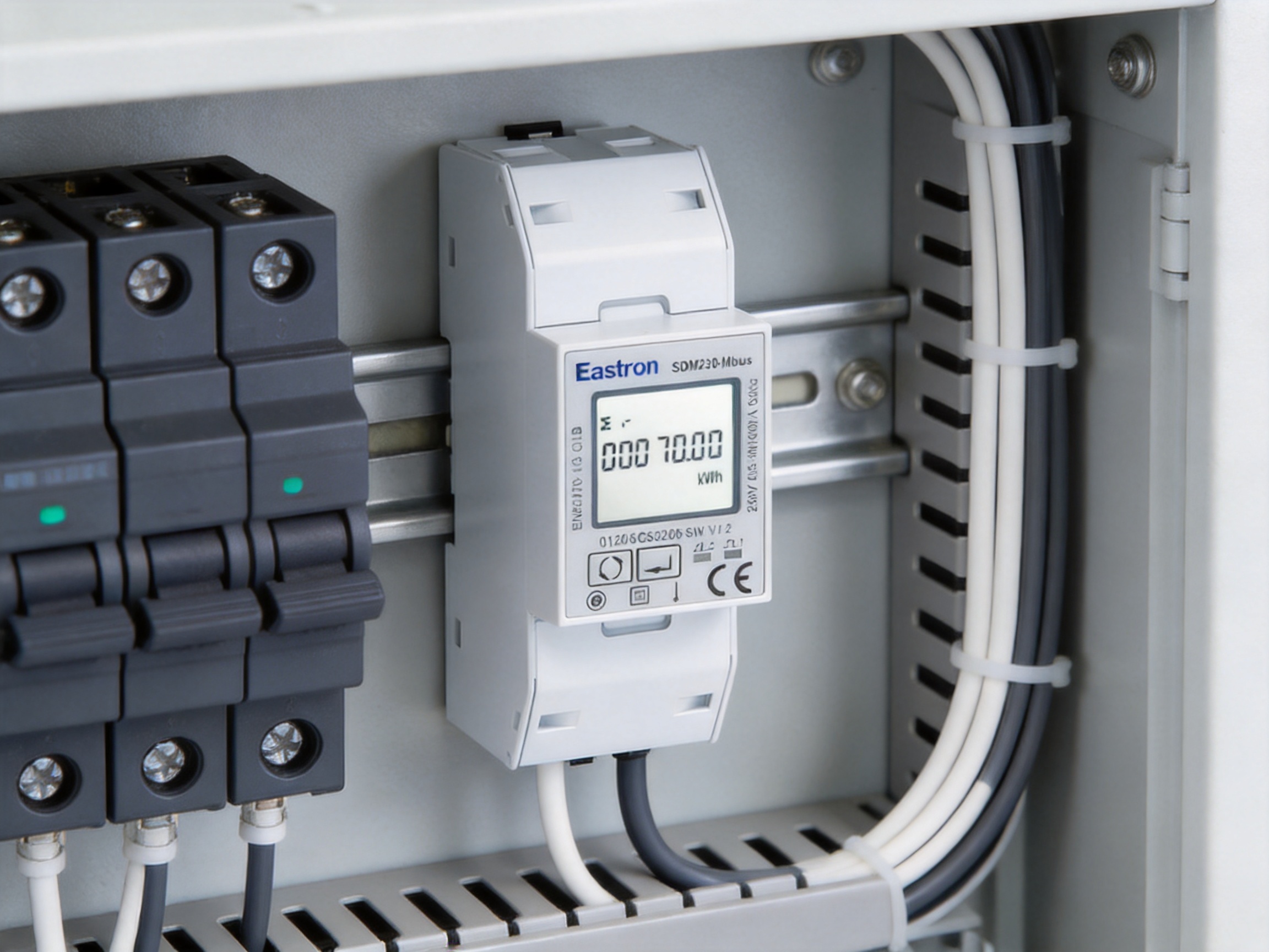
A basic energy meter generally displays or records accumulated active energy. That may be sufficient for a simple consumption check, but it provides limited information when a system requires troubleshooting, remote supervision or bidirectional operation.
The multifunctional meter provides several advantages over a basic kWh-only device:
• It measures several electrical quantities rather than active energy alone.
• It supports both local LCD reading and remote M-Bus communication.
• It provides two pulse outputs for integration with external counters and controllers.
• It supports bidirectional energy measurement for import and export applications.
• It offers direct connection up to 65 A without external current transformers.
• It fits in a compact two-module DIN-rail housing.
• It carries the stated MID approval and ETL listing credentials.
These features can reduce the number of additional devices required in an installation. A basic kWh meter may need a separate voltage monitor, current meter, communication converter and pulse module to achieve similar functionality. Combining these functions in one enclosure can reduce panel congestion and simplify commissioning.
Current-transformer metering is valuable for high-current applications, but it is not always necessary for smaller circuits. CT systems require additional physical space and careful attention to polarity, ratios, secondary wiring and terminal safety.
For circuits within the meter’s current range, direct connection can simplify design. The installer does not need to select a separate CT ratio or install a CT shorting arrangement. The measurement path is more straightforward, and the panel bill of materials may be reduced.
Direct connection also makes the relationship between the circuit and the meter easier to understand during inspection. There are fewer components that can be incorrectly matched or miswired. This can reduce installation time and make fault diagnosis more efficient.
However, direct connection must never be used beyond the meter’s specified maximum current. Higher-current circuits require an appropriately rated measurement method, which may include CTs or other approved equipment. The advantage of direct connection applies specifically to suitable circuits within the product’s electrical limits.
Some installations use one meter for local display and another device for remote communication. This can work, but it increases the number of components and may create discrepancies between readings if the devices are configured differently.
The multifunctional meter combines front-panel display, energy measurement, pulse outputs and M-Bus communication in one unit. A single measurement point can therefore serve the installer, the operator and the central monitoring system.
Using one integrated meter can also simplify documentation. The electrical drawing, device schedule and communication list can reference one product rather than several coordinated devices. Maintenance teams have fewer separate units to identify and replace.
An integrated device can improve consistency because all reported values originate from the same measurement system. This is useful when the operator compares local readings with data collected by a building management platform.
The manufacturer is described as a high-tech producer of electricity meters, power analyzers, current sensors, communication modules and energy management systems. Its product range and technical specialization indicate a manufacturing focus centered on electrical measurement and energy management rather than a general-purpose electronics catalog.
The company maintains research and development teams in China and the United Kingdom. This international engineering structure supports product development, embedded software work, hardware design and communication technology development. Cooperation with universities and research institutions further contributes to the development of new metering technologies.
For a multifunctional meter, engineering capability is important because several technical disciplines must work together. The current and voltage sensing circuits must remain accurate, the microcontroller must process measurements consistently, the LCD must present data clearly, and the communication interface must operate reliably in a real electrical environment.
Embedded software is also essential. The meter must calculate energy registers, instantaneous parameters, power factor, frequency and directional energy values. It must manage display pages, pulse generation, communication addressing and configuration settings. Reliable firmware development and testing are therefore as important as the physical circuit design.
The company’s stated laboratory capabilities include electromagnetic compatibility, low-voltage directive, accuracy and environmental testing. Testing across these areas helps verify that products can operate safely and consistently under specified conditions.
EMC testing evaluates whether the meter can withstand electrical disturbances and whether it avoids causing unacceptable interference. This is particularly relevant in distribution boards containing contactors, switching power supplies, variable-speed equipment and communication devices.
Accuracy testing verifies the performance of the measurement circuits under defined voltage, current, power factor and frequency conditions. Environmental testing helps evaluate operation under changes in temperature, humidity and other specified conditions. Low-voltage testing addresses electrical safety and insulation-related requirements.
According to the supplied company information, the manufacturer follows an ISO 9001 quality management system. A quality management system provides a framework for controlling design changes, purchasing, production, inspection, corrective actions and customer feedback.
For energy meters, production control should cover more than visual assembly quality. Current-sensing components, voltage dividers, isolation structures, terminals, displays, communication components and calibration data all affect product performance. Traceability and controlled testing are important for maintaining consistency from batch to batch.
Automated or standardized assembly processes can help control soldering quality, component placement and production repeatability. Functional testing can verify that the display, buttons, pulse outputs, communication interface and measurement channels operate correctly before shipment.
Calibration and accuracy verification are especially important. Each meter must meet the relevant production tolerance before it leaves the factory. A controlled calibration process helps ensure that the measurement results are consistent with the published specifications.
Certification-related production approval and third-party testing also provide confidence for procurement teams. When a product is intended for regulated metering or professional energy management, documented production controls can be as important as the product’s feature list.
The meter should be installed by qualified personnel familiar with electrical distribution equipment and the regulations applicable to the installation location. Before installation, the technician should verify the system voltage, phase arrangement, expected current, conductor size, protective devices and communication requirements.
The meter is intended for a 1P2W single-phase AC system. The wiring must follow the approved diagram for the exact model. Line and neutral connections should be identified correctly, and all terminals should be tightened according to the applicable installation instructions.
The maximum current rating must not be exceeded. The 65 A maximum direct current is a product limit, not a recommendation to operate continuously at any arbitrary load without considering ambient temperature, enclosure conditions, conductor size and local electrical rules.
Communication wiring should be separated or arranged appropriately in relation to power wiring. The M-Bus master, cable length, network topology and addressing plan should be confirmed before commissioning. Each meter should have a unique address on the network.
After installation, the technician should check the display, verify voltage and current readings, confirm energy accumulation and test communication with the M-Bus master. If pulse outputs are used, their operation should also be verified with the connected receiving device.
The M-Bus communication address can be configured within the stated range of 1 to 250. The baud rate can be selected from 300 to 9600 bps. Parity and stop-bit settings should match the master device and the wider communication network.
A clear addressing plan is essential when multiple meters are installed. Addresses may be assigned according to apartment number, floor, panel, circuit or equipment identifier. Recording these addresses during commissioning makes future maintenance and data management easier.
The communication network should be tested under normal operating conditions. A meter may communicate correctly on a workbench but experience problems after installation if cable routing, electrical interference or network loading changes. Testing the completed system provides greater assurance than checking individual devices only.
Users should also confirm which data registers are available through the selected M-Bus implementation. The central software must be configured to interpret energy, power, voltage, current, power factor and other values correctly. Correct register mapping is necessary for meaningful reports and alarms.
Energy efficiency begins with measurement. Without reliable data, users may not know which loads consume the most energy, when peaks occur or whether an improvement project has delivered a measurable result.
The meter can provide the data needed to establish a baseline for a single-phase circuit. Operators can record consumption over days, weeks or seasons and compare the results with occupancy, production, weather or operating schedules.
Current and power readings may identify equipment that operates inefficiently or remains active when it should be idle. Power factor information can indicate whether a circuit’s apparent loading is high relative to useful active power. Frequency and voltage data can help confirm that supply conditions remain within expected values.
When several meters are networked, the facility can compare different zones or equipment groups. This makes it possible to prioritize improvement work, verify savings and create more accurate internal energy reports.
An energy meter is often installed in a location that is not visited frequently. Reliable long-term operation is therefore important. The product’s compact solid-state design, integrated measurement electronics and controlled manufacturing process are intended to support continuous service within the specified operating conditions.
Reliability depends on both the meter and the installation environment. The device should be protected from excessive heat, moisture, vibration, contamination and electrical conditions outside its ratings. Proper circuit protection and secure terminal connections are essential.
Periodic inspection can include checking terminal tightness, reviewing communication status, comparing readings with expected load behavior and examining the panel for signs of overheating or contamination. The front display and central monitoring data make these checks easier to perform.
A well-maintained meter can provide a long-term record of energy behavior. This historical information is valuable for detecting gradual changes, planning maintenance and evaluating the impact of new equipment or operating policies.
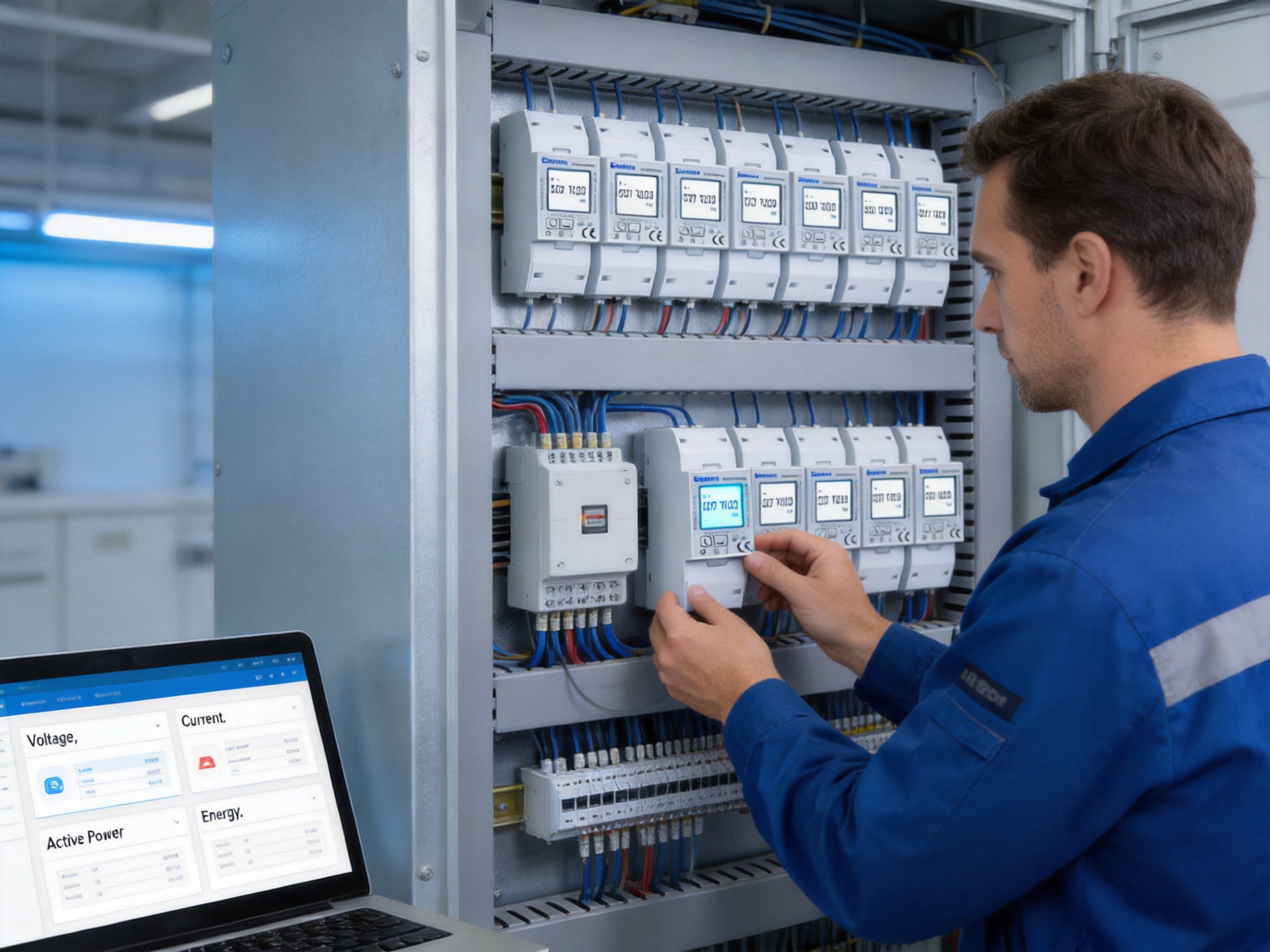
Before ordering the meter, buyers should confirm the following project requirements:
• The electrical system is single-phase, two-wire and compatible with the meter’s voltage range.
• The maximum expected current does not exceed 65 A for direct connection.
• The required energy direction, including import and export measurement, is supported.
• M-Bus communication is required or compatible with the planned monitoring system.
• Two pulse outputs are needed for the intended integration.
• The housing width and DIN-rail arrangement fit the available panel space.
• The required approval or listing applies to the intended market and application.
• The system software can read and interpret the meter’s communication data.
• The environmental conditions are within the product’s specified operating limits.
Buyers should distinguish the M-Bus model from related versions in the same product family. The product information identifies variants with pulse-only output, RS485 Modbus, dual tariffs and digital input. The ordering code should therefore be checked carefully to avoid receiving a communication interface that does not match the project design.
Modern energy infrastructure is becoming more distributed, more digital and more dependent on accurate information. Buildings generate electricity, charge vehicles, manage storage and operate many independent loads. A meter must therefore support more than traditional one-direction consumption recording.
This product responds to those needs through a combination of compact installation, direct connection, multifunction measurement, bidirectional capability, pulse outputs and M-Bus communication. It is small enough for practical panel integration but provides sufficient information for centralized energy management.
Its design is also suitable for staged projects. A customer may begin with local LCD monitoring, later add pulse collection and eventually connect the meter to a wider M-Bus network. This flexibility can help organizations expand their energy monitoring capabilities without replacing every installed device.
The product’s value is not based on one feature alone. Its advantage comes from the way the features work together. Direct connection simplifies the electrical installation, the LCD supports local service, multifunction measurement improves visibility, bidirectional operation supports distributed generation, and M-Bus communication enables centralized data collection.
The meter is designed for a single-phase, two-wire AC system identified as 1P2W or 1P+N. The wiring should follow the approved diagram for the exact model.
The maximum direct current is 65 A. The stated rated current is 10 A, the minimum current is 0.5 A and the starting current is 40 mA. The installation must remain within the product’s electrical ratings and local safety requirements.
No external current transformers are required for suitable circuits within the meter’s 65 A direct-connection limit. Higher-current circuits require a different measurement arrangement selected by a qualified designer.
The meter measures active energy, reactive energy, voltage, current, active power, power factor and frequency. Demand-related information is also identified in the product information.
Yes. The meter supports bidirectional measurement, making it suitable for applications where energy may be imported from or exported to the electrical network.
The M-Bus model uses M-Bus communication according to EN 13757-3. It supports addresses from 1 to 250 and baud rates from 300 to 9600 bps, with configurable parity and stop-bit options as specified.
Yes. The M-Bus version provides two pulse outputs. These can be used for energy pulse collection, external counters, data loggers or compatible control systems.
The meter occupies two DIN modules and has a stated width of approximately 36 mm. This compact size helps conserve space in distribution boards and control cabinets.
Active energy measurement is specified as IEC 62053-21 Class 1. Reactive energy measurement is specified as IEC 62053-23 Class 2.
Yes. Its bidirectional measurement capability, direct connection and M-Bus communication make it suitable for many single-phase photovoltaic monitoring applications within the specified electrical limits.
It can be used to monitor suitable single-phase charging circuits when the voltage and current remain within the meter’s ratings. The circuit design, protection and installation method must be reviewed by a qualified professional.
Yes. It includes a backlit LCD that allows users to view measurement information at the panel without relying solely on a remote monitoring platform.
No. The product family includes different communication variants. The M-Bus model uses M-Bus communication, while another version may use RS485 Modbus. The ordering code should be checked before purchase.
The supplied product information identifies the meter as MID approved and ETL listed by Intertek. The exact scope should be confirmed for the selected model and intended market.
Each meter should be assigned a unique address, and the baud rate, parity and stop-bit settings should match the master system. After wiring, the installer should test communication, confirm data mapping and verify the displayed values against expected circuit conditions.
Installation should be performed by qualified electrical personnel who understand single-phase distribution systems, DIN-rail equipment, communication wiring and applicable local regulations.
The M-Bus DIN-rail multifunctional single-phase ETL energy meter combines compact installation with a broad set of measurement and communication functions. Its 1P2W design, 65 A direct connection, backlit LCD, bidirectional measurement, two pulse outputs and M-Bus interface make it a practical choice for many residential, commercial, industrial, solar and electric vehicle applications.
Compared with basic kWh meters, it provides more information for energy analysis and troubleshooting. Compared with CT-based solutions for smaller circuits, it can reduce component count and simplify installation. Compared with separate local and remote devices, it integrates measurement, display and communication in one compact enclosure.
The manufacturer’s engineering resources, laboratory capabilities, quality management system and specialist focus on electricity measurement support the product’s suitability for professional applications. Controlled design, accuracy testing, EMC evaluation, safety verification and environmental testing are important strengths when a meter is expected to operate continuously in real electrical installations.
For project designers and facility managers, the product offers a balanced solution: enough measurement depth for meaningful energy management, enough communication capability for centralized monitoring, and a compact physical design that fits modern distribution equipment. When correctly selected, installed and commissioned, it can form a dependable measurement point within a wider energy management system.
IEC 62053-21, Electricity Metering Equipment: Particular Requirements for Static Meters for Active Energy.
IEC 62053-23, Electricity Metering Equipment: Particular Requirements for Static Meters for Reactive Energy.
EN 13757-3, Communication Systems for Meters and Remote Reading of Meters.
ISO 9001, Quality Management Systems: Requirements.
International Electrotechnical Commission, Guidance on Electrical Energy Measurement and Metering Equipment.
Product technical information for the SDM230 multifunctional single-phase energy meter, including electrical characteristics, communication parameters and output configurations.
Technical documentation concerning DIN-rail energy metering, direct-connected measurement and building energy management applications.
Your email address will not be published. Required fields are marked *

We develop and produce high performance electricity meters, power analyzers, current sensors, communication modules and management systems.
Address:NO. 52, Dongjin Road, Nanhu, Jiaxing, Zhejiang, China
Copyright @ Eastron Electronic Co., Ltd. All rights reserved
