

 English
 Español
 Deutsch
 中文简体


Product Consultation
Your email address will not be published. Required fields are marked *
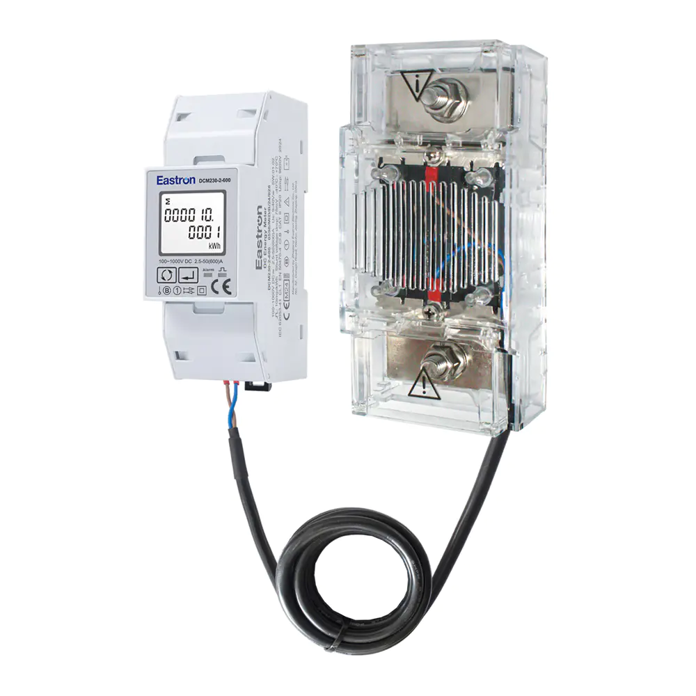
Max. Current 600A Modbus Multi-function DC Energy Meter for EV Charging Metering
Aug 02,2022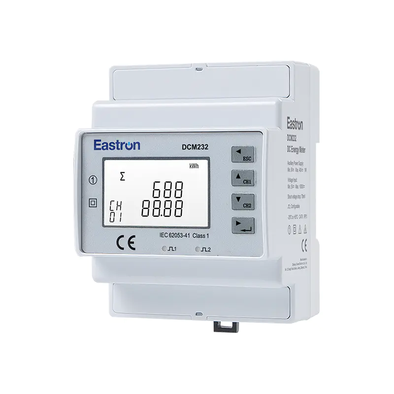
Din Rail Dual Channels DC Energy Monitoring Meter for EV Charging Metering
Aug 02,2022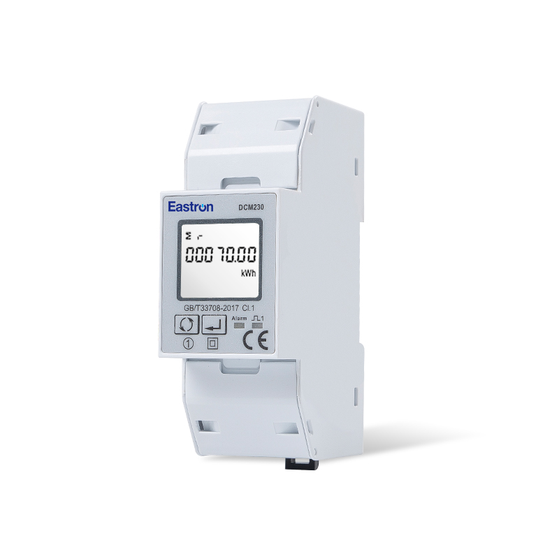
Din Rail DC Energy Monitoring Meter for EV Charging Metering
Aug 02,2022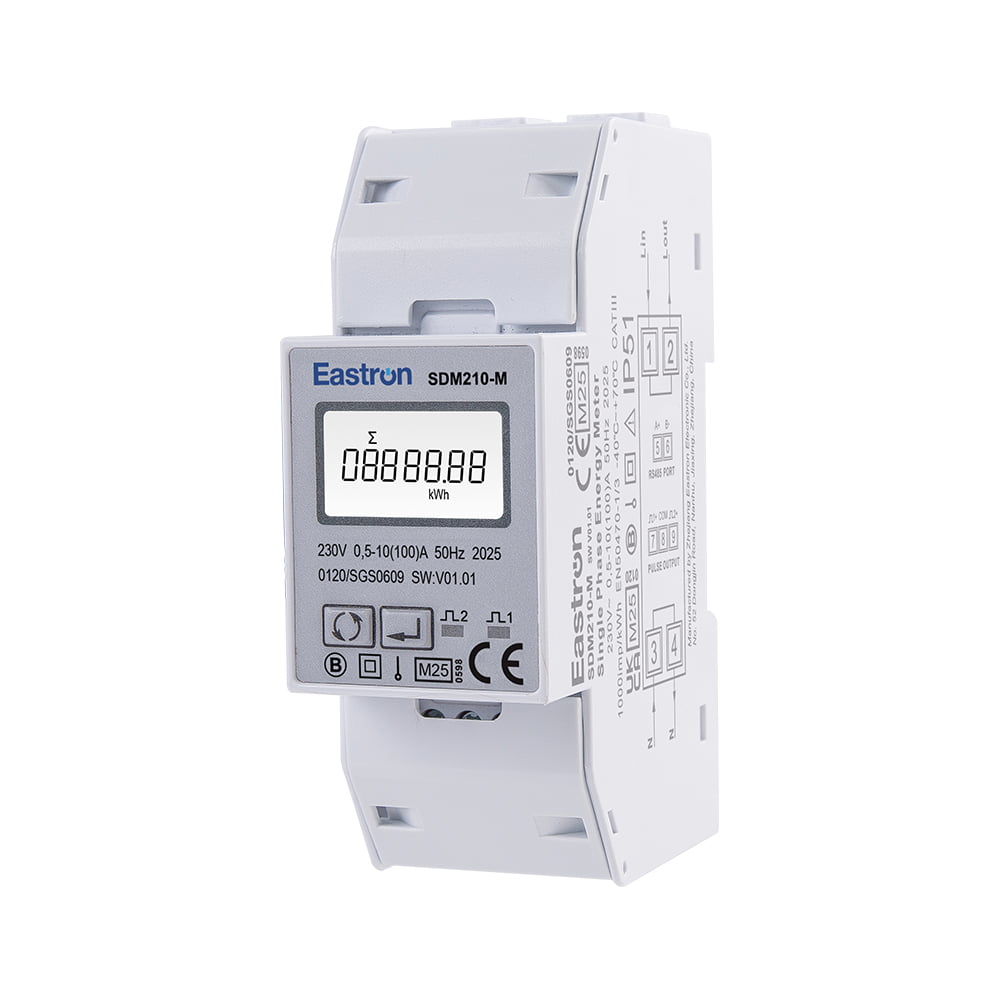
MID Approved Single Phase Energy Meter for EV Charging Metering
Nov 24,2022
MID & UL Approved Three Phase Din Rail Type Multi-function Energy Meter for EV Charging Metering
Nov 24,2022
MID/ UL Approved Single Phase Din Rail Type Multi-function Energy Meter for EV Charging Metering
Nov 24,2022Content


Modern direct-current infrastructure requires more than a basic voltage or current display. Electric vehicle charging stations, battery storage systems, photovoltaic installations, telecommunications power systems, industrial DC distribution panels, and energy-management platforms all need dependable information about how much energy is being produced, consumed, imported, or exported. The Max. Current 200A Modbus Din Rail DC Energy Meter with DC Shunt is designed for this role. Based on the DCM230-2-200 model, it combines high-voltage DC measurement, flexible shunt-based current sensing, bidirectional energy registration, pulse output, and RS485 Modbus RTU communication in a compact DIN-rail format.
The meter is designed for DC systems operating from 100 to 1000 V DC and supports current measurement up to 200 A when used with the supplied 75 mV DC shunt. Its measurement functions include voltage, current, power, active energy, and related operating data. Because the device can distinguish import and export energy, it is suitable for systems in which power may flow in either direction, including charging and discharging applications, regenerative systems, battery storage, and renewable-energy installations.
One of the most important features of this product is its combination of electrical capability and integration flexibility. A high-voltage input range enables one meter family to serve a wide variety of DC applications. The external shunt allows the current path to be measured without forcing the full load current through the meter body. RS485 communication makes the measured values accessible to supervisory software, PLCs, building-management systems, energy dashboards, and remote monitoring platforms. The DIN-rail enclosure helps installers place the meter neatly inside control cabinets and distribution boards.
The DCM230-2-200 is a DC energy meter developed for accurate monitoring of high-voltage DC power systems. It is supplied with a 75 mV shunt intended for current measurement up to 200 A in the specified configuration. The product measures the essential electrical parameters required for energy accounting and equipment supervision, while its communication interface makes it suitable for automated data collection.
The meter is identified as a Class 1.0 / B accuracy product. In practical terms, this makes it appropriate for many commercial, industrial, EV charging, renewable-energy, and energy-management applications in which reliable energy measurement is required. The detailed electrical characteristics specify measurement accuracy of 1% of maximum range for power and active energy, and 0.5% of maximum range for current and voltage. System designers should always select the correct range, wiring arrangement, shunt rating, and installation method for the intended application.
| Item | Specification |
|---|---|
| Product model | DCM230-2-200 |
| Meter type | DIN-rail DC energy meter |
| Voltage input | 100–1000 V DC |
| Maximum current | 200 A with the specified external shunt |
| Shunt | 75 mV, supplied as standard |
| Measurement direction | Bidirectional, import and export |
| Measured parameters | Voltage, current, power, active energy, and related DC system data |
| Accuracy classification | Class 1.0 / B |
| Communication | RS485 with MODBUS RTU |
| Communication address | 1–247 |
| Transmission distance | Up to 1000 m under suitable installation conditions |
| Transmission speed | 1200 to 19200 bps |
| Output | Pulse output and RS485 Modbus |
| Mounting | DIN rail |
The product package includes one DC shunt. This is a practical advantage for project planning because the installer receives the principal current-measurement component together with the meter. The shunt must nevertheless be installed according to the applicable wiring diagram, conductor-size requirements, thermal conditions, polarity conventions, and local electrical regulations.
DC systems are becoming increasingly important in energy infrastructure. Solar arrays generate direct current, batteries store and deliver direct current, EV batteries are charged through DC conversion stages, and many data, communications, and industrial systems use DC internally. Measuring only AC-side consumption may not reveal the actual performance of the DC equipment. A dedicated DC meter can provide a clearer view of energy movement at the point where it matters.
In an EV charging installation, for example, the meter can record the energy delivered to a vehicle or transferred through a charging power cabinet. In a battery-storage installation, it can help distinguish energy flowing into the battery from energy flowing out of it. In a photovoltaic system, it can support monitoring of DC generation before conversion to AC. In telecommunications or industrial backup-power systems, it can provide information about battery discharge, charging efficiency, and load behavior.
The 100–1000 V DC voltage range allows the DCM230-2-200 to support applications that extend beyond low-voltage control circuits. This range is especially relevant to high-power charging equipment, energy-storage systems, and renewable-energy equipment. A broad input range can simplify product selection and standardize the metering architecture across several projects with different nominal DC voltages.
High-voltage DC measurement also requires careful design. DC arcs do not extinguish in the same way as AC arcs, and incorrect isolation, fusing, conductor routing, or switching procedures can create serious hazards. The meter is therefore one part of a complete engineered system. Qualified personnel must confirm that the installation includes appropriate overcurrent protection, isolation, creepage and clearance distances, enclosure protection, grounding or bonding provisions, and safe commissioning procedures.
The meter uses a 75 mV external DC shunt to measure current. A shunt is a precision low-resistance component installed in the current path. As current passes through the shunt, a small voltage develops across it. The meter reads this voltage and calculates the corresponding current based on the shunt rating and configuration.
This arrangement offers several advantages over placing the entire load current through a small electronic meter enclosure. First, the current path is handled by a dedicated component designed for the required current. Second, the measurement electronics can remain physically separated from the main conductor path. Third, external shunts can be mounted in a location that supports better conductor routing and thermal management. This is particularly useful in control cabinets where high-current cables or busbars require substantial clearance and mechanical support.
For the 200 A version, the supplied 75 mV shunt is matched to the intended measurement configuration. Correct installation is essential. The power conductors must be connected to the shunt terminals with suitable torque and conductor capacity. The small-signal connections between the shunt and meter must be routed securely and kept away from sources of excessive electromagnetic interference where practical. The polarity of the shunt signal must be observed so that import and export energy are recorded correctly.
A shunt-based meter can also be more adaptable than a fixed internal current path. The product family includes versions associated with different current ranges, while the 200 A model is configured for the specified application. This flexibility helps equipment manufacturers select a meter that matches the electrical design rather than oversizing every installation or using a less suitable generic instrument.
Designers should remember that a shunt dissipates a small amount of power because it has a finite resistance. At high current, this heat must be considered in the cabinet layout. The shunt should be installed where its heat can be managed, and the surrounding materials must be suitable for the expected operating temperature. The meter’s own stated power-consumption specification should not be confused with the thermal behavior of the external high-current shunt.
Traditional energy meters were often designed around one-way energy flow. Modern systems are more dynamic. A battery may charge during one period and discharge during another. A charging station may transfer energy to a vehicle while regenerative operation or local energy management produces reverse flow. A solar-powered installation may send energy toward a DC bus, while the bus later supplies energy to another subsystem.
The DCM230-2-200 supports bidirectional measurement of imported and exported energy. This allows the system operator to separate the two directions of energy flow rather than treating all current as if it moved through the circuit in one direction. Such information can improve billing, load analysis, battery-performance evaluation, renewable-energy monitoring, and system diagnostics.
Correct polarity and wiring are fundamental to bidirectional measurement. The installation should follow the designated current direction and voltage-reference arrangement shown in the product wiring documentation. If the shunt polarity is reversed, the meter may report energy in the opposite direction from the intended system convention. Integrators should define whether “import” means energy entering a load, entering a battery, or entering another controlled subsystem, then configure their monitoring software consistently.
Bidirectional measurement is also valuable for energy-management algorithms. A controller can use real-time voltage, current, power, and cumulative energy values to determine whether a battery is charging, whether a DC bus is overloaded, or whether a renewable source is meeting the expected output. When these values are read through Modbus, they can be combined with temperature, state-of-charge, charger-status, and protection data from other devices.
Digital communication is a central strength of the product. The meter provides an RS485 interface using the MODBUS RTU protocol. This widely used industrial communication method allows the device to exchange data with PLCs, industrial computers, remote terminals, gateways, energy-management software, and charging-system controllers.
The communication address can be set from 1 to 247, allowing multiple compatible meters to share an RS485 network when correctly configured. The stated maximum transmission distance is up to 1000 m under suitable conditions. Actual performance depends on cable quality, network topology, termination, grounding, baud rate, electromagnetic environment, and the number of connected devices. A properly designed bus should use appropriate twisted-pair communication cable, avoid star-shaped wiring where possible, and follow the installation rules for RS485 networks.
Transmission speeds from 1200 to 19200 bps provide flexibility for different system requirements. Lower speeds may offer greater tolerance in difficult communication environments or on long cable runs, while higher speeds can support faster polling when the network and wiring conditions are suitable. The meter supports no parity as the default, with odd and even parity options, and one or two stop bits. These settings enable the device to be matched with the host controller.
Before commissioning, the integrator should ensure that every device on the bus has a unique address and that all devices use compatible baud rate, parity, and stop-bit settings. The communication master should also implement sensible polling intervals, timeout handling, and error checking. Modbus RTU includes a cyclic redundancy check for data integrity, but reliable system design still requires suitable cable routing and protection against electrical noise.
RS485 communication can reduce the need for local manual readings. A central system can collect voltage, current, power, and energy information from multiple charging points or distribution branches. Data can then be stored for reports, alarms, maintenance planning, capacity management, and performance analysis. Because the meter also has a pulse output, it can support applications that require a simple pulse-based energy signal in addition to full digital communication.
DC energy measurement is especially important in EV charging equipment. A charger may need to know how much energy has been delivered, how much power is currently being transferred, and whether the energy direction or operating condition has changed. These values support charging-session records, equipment diagnostics, load balancing, and infrastructure management.
The DCM230-2-200 is designed for use in EV charging-related DC systems. Its high-voltage input range is suited to charging architectures that operate at elevated DC bus voltages. Its 200 A maximum-current configuration can support substantial charging power, depending on the actual voltage, thermal design, protection equipment, and system operating limits.
For example, at a nominal DC voltage of 800 V and a current of 200 A, the theoretical electrical power is approximately 160 kW. This calculation is not a statement that every installation should operate continuously at that level. It simply illustrates why high-voltage, high-current measurement is relevant to modern charging systems. The actual permissible power depends on the charger design, shunt rating, cable size, protection devices, cooling, connector rating, and applicable standards.
In a charging cabinet, the meter can be positioned to monitor the DC output, the DC input to a conversion stage, or another defined measurement point. The location should be selected according to the required metering boundary. If the meter is intended for commercial energy accounting, the system designer must ensure that the meter’s location, accuracy, calibration, sealing, and data handling meet the requirements of the applicable jurisdiction and contract.
Communication with a charging controller allows live measurements to be integrated into operational logic. The controller may use the data to detect abnormal current, verify that a commanded power level is being delivered, or record energy for each charging event. The pulse output can serve as an additional signal for a compatible counter or control system.
Battery energy-storage systems require measurements at several points. Operators may need to monitor the DC battery current, the energy entering the battery, the energy leaving the battery, and the power exchanged with a converter. A bidirectional DC meter can support this work by recording both directions of energy flow.
For renewable-energy systems, the meter can provide visibility on the DC side of a photovoltaic installation. This may help compare array output with inverter input, identify abnormal string behavior when used with suitable system architecture, or evaluate the energy contribution of a DC source. A broad voltage range gives designers flexibility when dealing with different array or battery configurations.
In battery storage, data from the meter can be combined with battery-management-system information. The energy meter may measure the external DC flow while the battery-management system monitors cell voltage, temperature, balancing, and protection status. Together, these data sources can help determine round-trip performance, standby losses, charge and discharge patterns, and operating efficiency.
Bidirectional energy data is particularly useful for distinguishing charging losses from discharging output. If a system records only absolute current, it may be difficult to determine whether energy is entering or leaving the storage device. Import and export registers provide a more useful basis for energy accounting and operational reports.
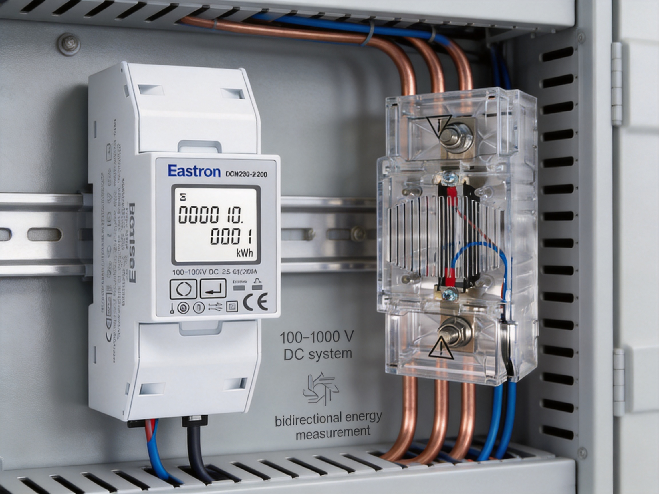
The DIN-rail format is widely used in electrical distribution and control cabinets. It gives installers a standardized mounting method and helps organize meters alongside circuit protection, contactors, terminal blocks, relays, communication equipment, and control devices.
A DIN-rail meter can be incorporated into new equipment or retrofit projects with relatively little mechanical modification. The compact form factor helps reduce panel space compared with larger bench-style instruments or separate local displays and communication modules. The result is a cleaner cabinet layout and more consistent manufacturing process for equipment builders.
Even with standardized mounting, the installation must provide adequate spacing, ventilation, and access. High-voltage terminals should be segregated from low-voltage communication wiring where appropriate. The external shunt requires its own mechanical support and should not be left suspended by electrical conductors. High-current cables must be routed to minimize stress on the shunt and its terminals.
Installers should use the supplied wiring diagram and dimension information when designing the panel. Terminal identification, polarity, fuse arrangements, communication connections, pulse-output wiring, and voltage-reference connections must all be verified before power is applied. The product’s intended wiring arrangement should not be modified without confirming the effect on measurement accuracy and safety.
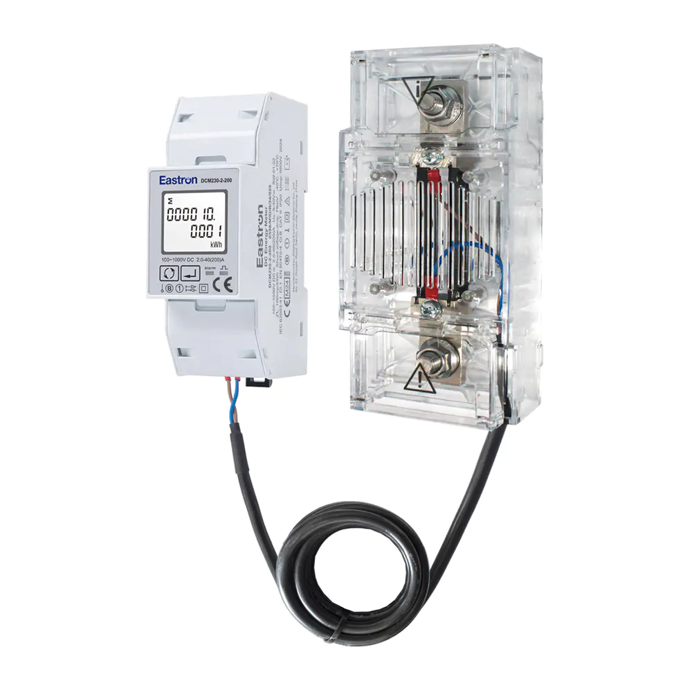
Max. Current 200A Modbus Din Rail DC Energy Meter with DC Shunt
Measurement accuracy is one of the defining characteristics of an energy meter. The DCM230-2-200 is specified as a Class 1.0 / B meter and provides stated accuracy values for its principal measurements. The detailed specifications identify 1% of maximum range for power and active energy, and 0.5% of maximum range for current and voltage.
These values should be interpreted within the conditions of the complete measurement chain. The meter, shunt, wiring, temperature, installation position, electromagnetic environment, and operating range can all influence the final result. A high-quality instrument cannot compensate for a poorly rated shunt, loose terminal, incorrect polarity, excessive conductor heating, or an unsuitable installation environment.
For project engineers, the phrase “accuracy of maximum range” is important. It differs from accuracy expressed as a percentage of the instantaneous reading. At low load levels, the absolute error associated with full-scale specifications may represent a larger percentage of the measured value. Therefore, the expected load profile should be reviewed when selecting the meter and interpreting data.
In applications requiring formal revenue measurement, users should also review local legal-metrology requirements, calibration intervals, environmental conditions, sealing provisions, and verification procedures. The meter is identified as MID approved and described as compliant with EN 50470-4 and IEC 62053-41 in the supplied product material. The responsible project party should confirm the exact approval scope and whether the intended DC application falls within the applicable certification and regulatory framework.
Commissioning checks can include verifying the voltage reading against a calibrated reference, checking current direction, confirming that power changes sign as expected during reverse flow, and comparing accumulated energy with an independent reference over a suitable test period. Communication registers should be tested under both normal and abnormal conditions, including loss and restoration of the RS485 connection.
Many generic meters can display voltage and current, but fewer combine high-voltage DC operation, a 200 A shunt-based current configuration, bidirectional energy measurement, digital communication, pulse output, and a DIN-rail enclosure in one product. This combination reduces the need to combine several separate instruments.
Compared with a simple local display meter, the DCM230-2-200 offers stronger integration potential. RS485 Modbus allows data to be collected automatically, while a pulse output provides an additional interface for systems that do not require full register-based communication. The result is better suited to distributed infrastructure and connected energy-management systems.
Compared with a one-direction meter, the bidirectional function is more appropriate for batteries, renewable sources, regenerative equipment, and charging systems with changing energy flow. It can help avoid the ambiguity that occurs when a system records reverse current as a reduction in a single cumulative value without clearly separating import and export.
Compared with a meter that measures current through an internal path, an external shunt can make high-current system design more practical. The main current path can be constructed using appropriately sized conductors and a dedicated shunt, while the electronic meter handles the low-level measurement signal. This arrangement can provide greater installation flexibility and clearer separation between power wiring and measurement electronics.
Compared with narrow-voltage-range instruments, the 100–1000 V DC input range supports a wider variety of applications. Equipment manufacturers may be able to standardize on one product family across different DC bus configurations, reducing engineering variation, inventory complexity, and training requirements.
The product also benefits from being part of a broader measurement portfolio. A supplier with products covering AC meters, multifunction meters, MID energy meters, power analyzers, current transformers, gateways, relays, switches, and systems solutions can provide a more coordinated approach to energy measurement. This broader capability can be valuable when a project includes both AC and DC measurement points or requires communication between meters and a central gateway.
The manufacturer, Eastron Electronic Co., Ltd., is headquartered in Jiaxing, Zhejiang, China, near major technology and manufacturing centers including Shanghai, Hangzhou, and Jiangsu. The company develops and produces electricity meters, power analyzers, current sensors, communication modules, and energy-management systems. This product focus supports accumulated experience in electrical measurement, embedded electronics, communication, and industrial product development.
The company describes a continuous investment in research and development, supported by development teams in China and the United Kingdom. Cooperation with universities and professional institutions contributes to the development of new technologies and products for electricity measurement. For a product such as the DCM230-2-200, this type of multidisciplinary capability is relevant because accurate metering depends on more than the display or enclosure. It requires sensor-interface design, signal processing, firmware, calibration, communication management, insulation considerations, and production control.
The company has established a professional laboratory capable of performing EMC, LVD, accuracy, and environmental tests according to IEC, EN, GB, and UL standards. These testing capabilities support a more systematic development and validation process. EMC testing helps evaluate resistance to and emissions of electromagnetic disturbance. Low-voltage and safety-related testing helps verify relevant electrical design characteristics. Accuracy testing supports calibration and performance verification, while environmental testing helps assess behavior under defined operating conditions.
In-house or closely controlled laboratory capability can provide several manufacturing advantages. Product designs can be evaluated earlier in the development cycle, test results can be used to refine hardware and firmware, and production samples can be checked using repeatable procedures. This reduces dependence on informal inspection and creates a stronger foundation for consistent product quality.
The company also reports patented technologies in software, embedded software, and hardware. For intelligent meters, embedded software is especially important. It controls data acquisition, parameter calculation, direction recognition, energy accumulation, display behavior, communication registers, fault handling, and configuration. Stable firmware is essential because the meter may be installed in a system expected to operate continuously for many years.
Quality management is another stated strength. The company follows the ISO 9001 quality-management system, and its production is approved by SGS according to MID standards. A quality-management system helps formalize design control, purchasing, manufacturing, inspection, nonconformance management, corrective action, traceability, and customer feedback. These processes are particularly valuable for products used in metering applications, where consistency between units is as important as the performance of an individual prototype.
The stated production and testing capabilities are relevant to the DCM230-2-200 because the product must coordinate several critical functions. The voltage input must be suitable for the specified DC range. The shunt interface must correctly interpret a 75 mV signal. The energy calculation must remain consistent during both import and export operation. The Modbus interface must communicate reliably with external systems. The enclosure must support DIN-rail installation, and production testing must confirm that the finished unit performs as designed.
The meter should be considered as part of a complete measurement architecture rather than as an isolated component. Before selecting the installation point, the project team should define the required measurement boundary. Possible boundaries include energy entering a charger, energy delivered from a charger, energy entering or leaving a battery, DC generation from a renewable source, or power supplied to a specific industrial load.
The choice of location affects the meaning of the recorded energy. A meter installed before a converter measures different losses from a meter installed after the converter. A battery-side meter may include wiring and conversion losses that would not appear in a grid-side meter. Clear documentation prevents later confusion when operators compare readings from multiple points.
The shunt rating, conductor cross-section, voltage insulation, fuse coordination, and thermal environment must all match the system. Engineers should consider continuous current, short-term overload, ambient temperature, enclosure temperature, and possible fault conditions. The meter’s maximum current specification must not be treated as permission to exceed the current rating of any other component.
Communication architecture should be planned at the same time as power wiring. RS485 cable routes should be separated from high-current switching conductors where possible. Network termination should be applied according to the bus design. If several meters are installed, address allocation should be documented in the panel schedule and commissioning records.
Data architecture is equally important. The host system should define how voltage, current, power, import energy, export energy, status information, and communication faults will be stored and displayed. Scaling factors and units must be confirmed from the product communication documentation. Operators should also decide whether energy registers are resettable, cumulative, or periodically archived by the supervisory software.
Only qualified personnel should install and commission equipment connected to high-voltage DC systems. Before beginning work, the system must be isolated using approved procedures, and the absence of voltage must be verified with suitable instruments. DC systems can remain energized through batteries, capacitors, photovoltaic sources, or other stored-energy devices even when an upstream switch is open.
The meter should be mounted securely on the specified DIN rail, and the shunt should be installed in a mechanically stable position. Power conductors should be selected for the expected current and temperature. Terminal connections should be tightened according to the relevant component requirements, and the installation should be inspected for loose strands, damaged insulation, incorrect polarity, and inadequate clearance.
The voltage input connections should be protected and isolated in accordance with the system design. The shunt signal wires should be identified clearly and connected to the correct terminals. If the shunt polarity is reversed, the meter’s import and export interpretation may also be reversed. Communication conductors should be checked for correct A/B or positive/negative assignment according to the installation documentation.
After wiring, the system should be inspected before energization. The commissioning sequence may include checking continuity where appropriate, confirming isolation between circuits, verifying the shunt connection, checking the communication address, and confirming the host-controller settings. Once energized, the operator should compare displayed or communicated voltage with an independent reference and apply a known or expected load to verify current and power readings.
Where reverse energy flow is part of the application, the commissioning procedure should include a controlled reverse-flow test. The resulting power and energy direction should match the project’s defined import/export convention. Communication logs should be reviewed for timeouts, invalid responses, address conflicts, or incorrect scaling.
Solid-state energy meters generally require less routine maintenance than mechanical measuring devices, but periodic inspection remains important. Maintenance personnel should check the condition of the enclosure, terminal connections, communication cable, shunt mounting, conductor insulation, and cabinet ventilation. Signs of overheating, discoloration, corrosion, moisture, or mechanical stress should be investigated promptly.
Accumulated energy readings should be included in the site’s data-backup or reporting strategy. If the meter is replaced, the outgoing meter’s final readings should be recorded and the incoming meter’s initial configuration should be documented. The replacement must use compatible shunt characteristics and communication settings to preserve measurement continuity.
Communication monitoring can provide early warning of system problems. A supervisory system may generate an alarm if the meter stops responding, reports an abnormal voltage, shows unexpected reverse power, or experiences a prolonged loss of data. These alarms can help distinguish a genuine electrical event from a network or configuration problem.
Calibration and verification intervals should be established according to the application, regulatory requirements, environmental conditions, and quality policy. Commercial or legally controlled installations may require more formal verification than an internal engineering-monitoring point. The meter’s MID status and stated standards should be reviewed together with the project’s local compliance obligations.
Once integrated into a supervisory system, the meter can contribute to detailed energy analysis. Real-time voltage and current data can show the operating condition of a DC bus. Power values can reveal demand peaks and load changes. Cumulative import and export energy can support daily, monthly, or session-based reporting.
In an EV charging network, this data can be used to compare energy delivered among chargers, identify underperforming units, and plan capacity upgrades. In a battery system, it can support charge-discharge profiles, efficiency calculations, and cycle analysis. In a renewable-energy installation, it can help compare production with expected solar or operational conditions.
Energy data can also support predictive maintenance. A gradual increase in voltage drop, unusual current variation, or a change in energy behavior may indicate loose connections, cooling problems, declining battery performance, or a developing equipment fault. Such analysis is most effective when data is collected consistently and combined with operating context.
The RS485 Modbus interface makes the meter suitable for gateways and larger systems. A gateway can collect data from multiple meters, translate it into another protocol, send it to a cloud platform, or connect it to an enterprise energy-management system. This allows the same field meter to participate in a local control loop and a broader reporting environment.
When selecting this meter, the first consideration should be the nominal and maximum DC voltage. The system must remain within the stated 100–1000 V DC input range, including expected operating variation. The second consideration is current. The 200 A model must be used with the appropriate 75 mV shunt and the complete current path must be rated for the intended load.
The measurement direction should also be defined. If energy can flow both ways, the project should confirm how import and export registers will be interpreted and reported. If energy flows only one way, bidirectional capability still provides flexibility for future system changes.
Communication requirements should be reviewed early. The host must support RS485 Modbus RTU or use a suitable gateway. Address, baud rate, parity, stop bits, register mapping, cable length, and network topology should be included in the design documents. If a simple pulse signal is preferred, the pulse output should be matched with the receiving device.
Environmental and mechanical conditions matter as well. The panel must provide suitable protection against moisture, dust, vibration, heat, and accidental contact. The shunt may require more space and thermal consideration than the meter itself. The complete assembly should be evaluated rather than selecting the meter based only on its front-panel dimensions.
Finally, the project team should review certification and compliance requirements. The product material identifies MID approval and references EN 50470-4 and IEC 62053-41. The applicable approval scope, marking, installation conditions, and local legal requirements should be confirmed before using the meter for regulated billing or formal energy settlement.
The DCM230-2-200 is configured for a maximum current of 200 A when used with the specified 75 mV DC shunt. The shunt, conductors, terminals, protective equipment, and thermal design must all be suitable for the intended current.
The specified input-voltage range is 100–1000 V DC. The system voltage, including normal operating variation, must remain within this range.
Yes. The package includes one DC shunt. The supplied shunt is specified as 75 mV for the standard configuration.
Yes. The meter supports bidirectional measurement, including imported and exported energy. Correct polarity and system configuration are necessary for the directions to be recorded as intended.
The meter uses RS485 communication with MODBUS RTU. It supports configurable addresses from 1 to 247, transmission speeds from 1200 to 19200 bps, and selectable parity and stop-bit settings.
The meter measures key DC system parameters including voltage, current, power, and active energy. The complete available data set should be confirmed in the communication documentation for the specific product configuration.
Yes. The DCM230-2 series is designed for DC energy measurement and is identified for EV charger applications. Its high-voltage range, external shunt, bidirectional measurement, pulse output, and Modbus communication are useful in charging cabinets and charging-management systems.
Yes. The meter is suitable for monitoring DC energy entering or leaving a battery system, provided that the voltage, current, shunt, insulation, protection, and environmental requirements are properly addressed.
Class 1.0 / B identifies the product’s stated accuracy classification. The detailed specifications list 1% of maximum range for power and active energy, and 0.5% of maximum range for current and voltage. Application-specific requirements should be reviewed before selecting the meter for regulated measurement.
The network should use suitable twisted-pair communication cable, compatible device settings, unique addresses, appropriate termination, and a bus-oriented topology. Communication wiring should be routed carefully in high-voltage and high-current environments to reduce interference.
Yes. The product information specifies pulse output together with RS485 Modbus communication. The pulse output can be connected to a compatible counter or control system.
An external shunt allows the high-current path to be handled by a dedicated component while the meter measures the low-voltage signal generated across the shunt. This can simplify high-current cabinet design, improve conductor flexibility, and separate the measurement electronics from the main current path.
Yes. Because the meter may be connected to systems up to 1000 V DC and currents up to 200 A, installation and commissioning should be performed by qualified personnel using appropriate isolation, protection, wiring, and verification procedures.
The Max. Current 200A Modbus Din Rail DC Energy Meter with DC Shunt is a versatile instrument for high-voltage DC energy measurement. Its 100–1000 V DC input range, 200 A current capability, supplied 75 mV shunt, Class 1.0 / B accuracy classification, bidirectional measurement, pulse output, and RS485 Modbus RTU communication address the practical requirements of modern energy infrastructure.
Its strongest value comes from the combination of functions. The meter is not limited to local voltage and current indication. It can form part of an automated measurement architecture for EV charging, battery storage, photovoltaic generation, industrial DC distribution, telecommunications power, and other energy systems. The DIN-rail design supports organized cabinet installation, while the external shunt provides flexibility for high-current applications.
The manufacturer’s experience in electricity meters, power analyzers, sensors, communication modules, and energy-management systems provides a broad technical foundation. Research and development resources, laboratory testing for EMC, LVD, accuracy, and environmental performance, ISO 9001 quality management, reported MID-related production approval, and experience serving international markets further support the product’s position in professional energy-measurement applications.
As with any high-voltage measuring device, correct application and installation are essential. Engineers must verify voltage, current, shunt compatibility, polarity, thermal conditions, protective arrangements, communication settings, and certification requirements. When integrated into a properly designed system, the DCM230-2-200 can provide dependable visibility into DC energy flow and support more efficient, accountable, and intelligent operation of modern electrical infrastructure.
1. Product technical information for the DCM230-2-200 DC energy meter, including voltage, current, shunt, accuracy, communication, and application data.
2. Manufacturer-provided wiring and dimensional information for the DCM230-2 series.
3. EN 50470-4, Electricity metering equipment and requirements for active energy meters.
4. IEC 62053-41, Electricity metering equipment and requirements for static meters for DC energy.
5. IEC 61158, Industrial communication networks and fieldbus communication principles.
6. MODBUS Application Protocol Specification, serial communication principles and RTU data exchange.
7. ISO 9001, Quality management systems and organizational quality requirements.
8. European Union Directive 2014/32/EU concerning measuring instruments and applicable conformity principles.
Your email address will not be published. Required fields are marked *

We develop and produce high performance electricity meters, power analyzers, current sensors, communication modules and management systems.
Address:NO. 52, Dongjin Road, Nanhu, Jiaxing, Zhejiang, China
Copyright @ Eastron Electronic Co., Ltd. All rights reserved
