

 English
 Español
 Deutsch
 中文简体


Product Consultation
Your email address will not be published. Required fields are marked *
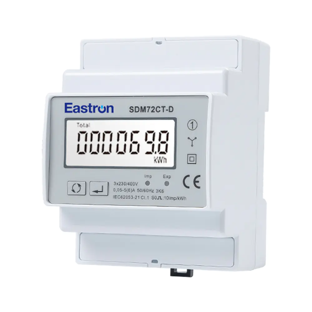
CT Type Din Rail Three Phase Electronic kWh meter with Pulse Output
Aug 11,2022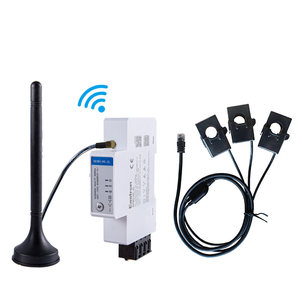
CT Type Three Phase Din Rail Wifi Energy Meter for PV Metering
May 30,2025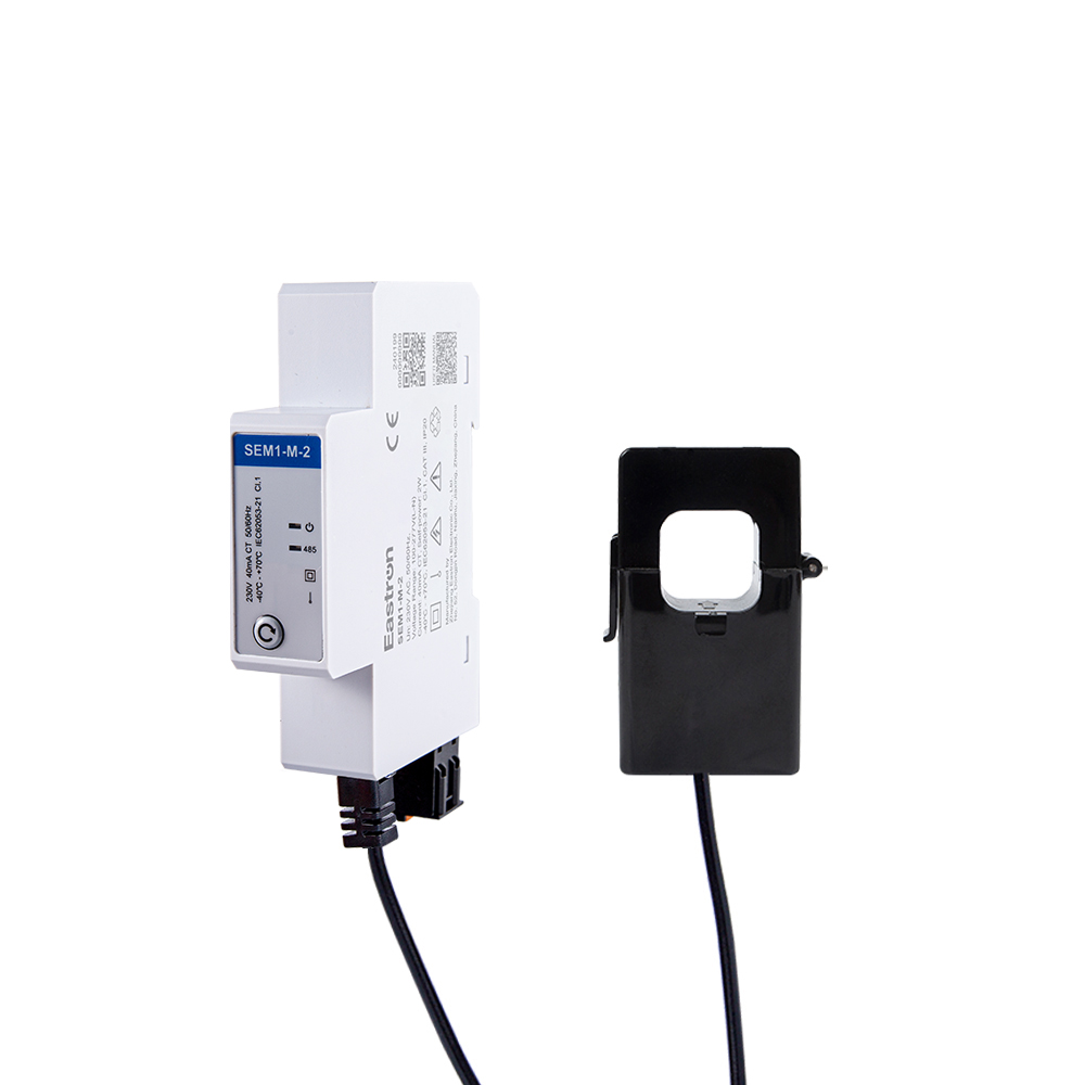
CT Type RS485 Modbus Single Phase Din Rail Energy Meter for PV Metering
May 30,2025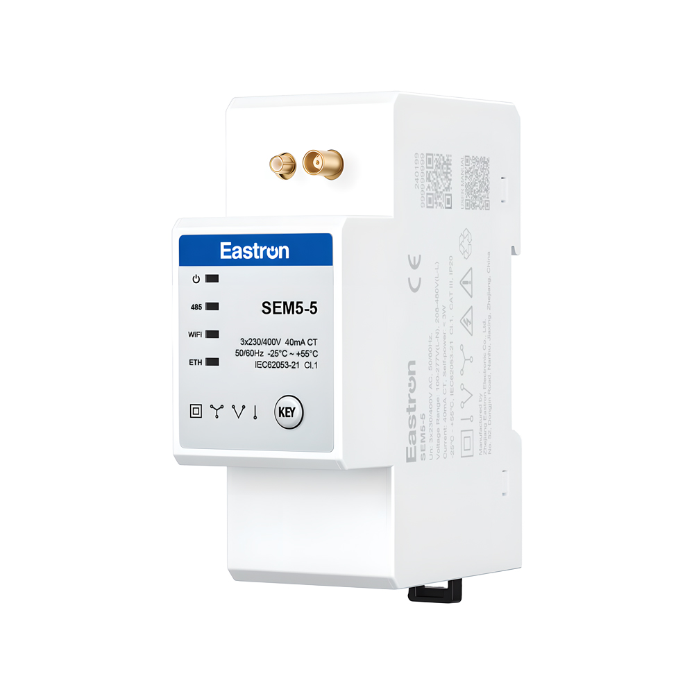
CT Operated Wireless Three Phase Energy Meter for PV Metering
May 30,2025
Resettable Din Rail Three Phase Electronic kWh meter with Pulse Output
Aug 11,2022
MID/UL CT Type Din Rail Three Phase Multi-function Energy Meter for EV Charging Metering
Nov 24,2022Content
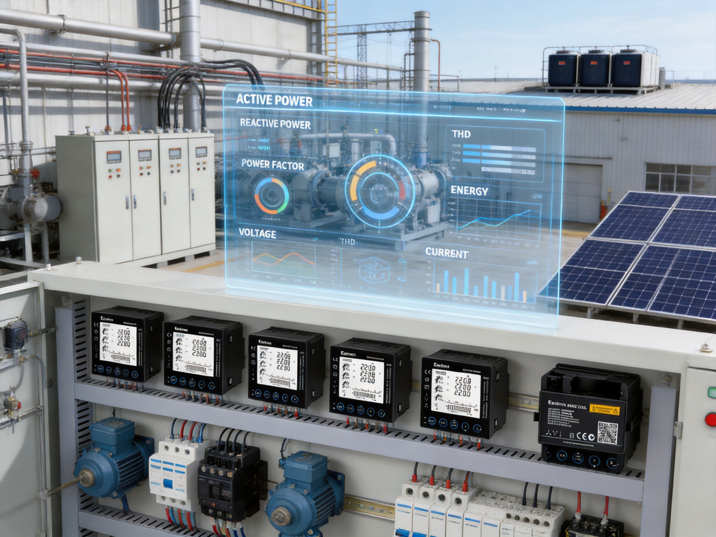
Modern electrical installations require more than a simple voltage or current reading. Facility operators, panel builders, energy managers, and maintenance engineers need a clear view of how electricity is being consumed, where power quality is changing, and whether equipment is operating within acceptable limits. A panel-mounted multifunction power analyzer provides this broader view by combining electrical measurement, energy monitoring, harmonic analysis, local indication, pulse outputs, and digital communication in one compact instrument.
The Smart X96-1A is designed for this role. It is an RJ CT type, RS485 Modbus panel-mounted multifunction power analyzer for three-phase electrical systems. It supports 3P3W and 3P4W configurations, accepts a 100 mA current-transformer signal, and measures key electrical quantities including voltage, current, frequency, active power, reactive power, apparent power, power factor, active energy, reactive energy, and harmonic distortion. It also provides two pulse outputs and an RS485 Modbus RTU interface for integration into supervisory systems.
The analyzer combines a 96 mm panel format with a front display, self-powering capability, plug-in current-transformer connection, and measurement accuracy suitable for demanding commercial and industrial applications. Its ability to measure harmonics up to the 63rd order gives users a more detailed understanding of power quality than instruments limited to basic RMS values. At the same time, its RJ12 current connection and pre-cut wiring approach can simplify installation compared with meters that require conventional high-current CT wiring.
This article examines the instrument’s operating characteristics, measurement functions, connectivity, installation benefits, manufacturing strengths, quality considerations, application value, and practical selection criteria. It also explains how an advanced electricity-meter manufacturer can support reliable deployment through product development, laboratory testing, standards awareness, production control, and international technical service.
Electrical networks are becoming more complex. Variable-frequency drives, switch-mode power supplies, LED lighting, data-center equipment, electric-vehicle chargers, solar inverters, battery systems, and automated machinery all introduce different load characteristics. A basic ammeter may show that current is flowing, but it cannot explain whether the current is balanced, whether voltage is stable, how much reactive power is present, or whether harmonic distortion is increasing.
A multifunction power analyzer addresses these needs by collecting several related measurements in a single device. Instead of installing separate meters for voltage, current, frequency, power factor, energy, and power quality, a single panel instrument can provide a coordinated set of readings. This reduces panel space requirements and gives operators a consistent measurement point.
The value of a multifunction analyzer is especially clear when troubleshooting. If a motor is drawing more current than expected, the engineer can compare current, voltage, power factor, active power, reactive power, and harmonic distortion. If a facility’s utility bill is increasing, energy registers and load information can help identify the cause. If a communication system receives unexpected data, local display readings can be compared with values collected over Modbus.
The Smart X96-1A is intended to serve as both a local display instrument and a data source for energy-management or building-management systems. The backlit LCD makes the measured values available at the panel, while RS485 Modbus RTU permits remote collection. Pulse outputs provide an additional method of transferring energy or event information to compatible equipment.
The analyzer is designed for direct panel mounting in a 96 by 96 mm format. This is a widely used industrial instrument dimension, making it suitable for switchboards, distribution panels, control cabinets, machine panels, energy-monitoring enclosures, and retrofit projects that use standard square panel cut-outs.
Its measurement architecture supports three-phase, three-wire and three-phase, four-wire systems. The product description also identifies support for single-phase two-wire measurement functions. This flexibility allows the instrument to be applied to a range of low-voltage distribution arrangements, provided that the wiring configuration, nominal voltage, current-transformer ratio, and installation category are correctly selected for the application.
The current input is rated at 100 mA. Rather than routing the full load current through the analyzer, the instrument receives a low-level signal from compatible current transformers or current sensors. The maximum programmable current is identified as 9999 A, allowing the displayed primary current to be scaled for a wide range of electrical installations when the appropriate 100 mA CT ratio is used.
A key physical feature is the RJ12 type current-transformer connection. The plug-in connection is intended to make wiring faster and more consistent, particularly when a three-in-one current sensor and pre-cut wiring loom are used. Voltage connections use shrouded screw-clamp terminals, while the current side uses the RJ12 terminal. This separation helps distinguish voltage wiring from sensor wiring during installation and servicing.
The unit is self-powered from any of the three phases. This can simplify the power-supply arrangement because a separate auxiliary supply may not be necessary when the monitored three-phase system is available. Correct wiring and the manufacturer’s installation instructions remain essential, but self-powering can reduce additional components and make retrofit work more straightforward.
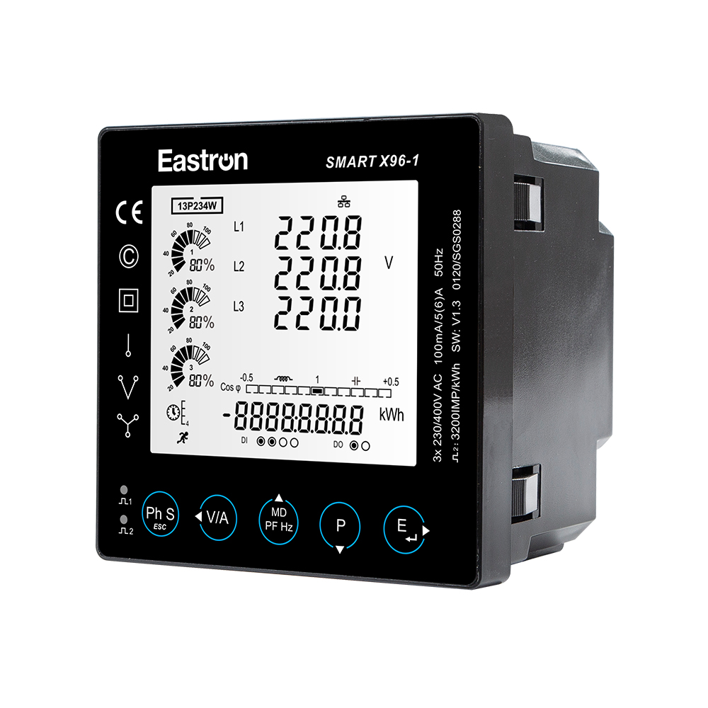
RJ CT Type RS485 Modbus Panel Mounted Multi-function Power Analyzer
The analyzer measures RMS quantities on three-phase AC systems, including the harmonic content present in the waveform. RMS measurement is important because many modern loads draw non-sinusoidal current. A simple average-based or sinusoidal-only instrument may not represent the actual heating effect or electrical stress associated with distorted waveforms.
RMS voltage and current values provide a practical indication of the electrical loading experienced by conductors, transformers, switchgear, and connected equipment. When harmonic currents are present, the RMS current can be higher than the fundamental-frequency current alone. Monitoring the complete RMS value therefore gives operators a more realistic basis for evaluating capacity and thermal loading.
Voltage measurement accuracy is specified as 0.5% of the range maximum, while current accuracy is also specified as 0.5% of the range maximum. These measurements form the foundation for the analyzer’s power and energy calculations.
Users can monitor phase-to-phase and phase-to-neutral values according to the system configuration. Comparing phase voltages can help identify imbalance, loose connections, supply abnormalities, or uneven transformer loading. Comparing phase currents can reveal unbalanced loads, overloaded conductors, or distribution problems within a facility.
Because the current input is supplied through an external 100 mA CT or current sensor, the selection and installation of the sensor are important parts of the overall measurement chain. The sensor primary rating should be appropriate for the expected load, the orientation should follow the indicated current direction, and the phase association should match the voltage phase. Incorrect phase pairing can cause inaccurate power factor and power readings even when the voltage and current values appear reasonable.
The analyzer measures active power, reactive power, and apparent power. Each value describes a different aspect of electrical operation.
Active power represents the portion of electrical power converted into useful work, heat, light, or another form of energy. It is commonly expressed in watts or kilowatts and is the principal quantity associated with energy consumption.
Reactive power is associated with the energy exchange between the electrical source and inductive or capacitive elements. Motors, transformers, reactors, and some power-conversion systems may draw substantial reactive power. Monitoring this value can help evaluate power-factor-correction performance and identify changes in the behavior of inductive loads.
Apparent power combines the effects of active and reactive power and is commonly expressed in volt-amperes or kilovolt-amperes. It is useful for evaluating the loading of transformers, generators, cables, and switchgear because equipment thermal limits are often related to current and apparent power rather than active power alone.
The accuracy specification for active, reactive, and apparent power is 1.0% of the range maximum. In practical terms, users should interpret the stated accuracy in relation to the configured measurement range, sensor performance, wiring quality, and operating conditions.
Active energy accuracy is identified as IEC 62053-22 Class 0.5S and IEC 62053-21 Class 1.0. Reactive energy accuracy is specified as 1.0% of range maximum according to IEC 62053-24. These classifications are important for users who need consistent energy records for internal allocation, efficiency analysis, tenant billing support, or system-performance evaluation.
The analyzer can measure imported and exported energy. This is increasingly useful in sites with distributed generation, energy storage, cogeneration, or bidirectional power flow. A facility may consume energy from the grid at some times and export energy at others. Distinguishing these directions helps operators understand the relationship between on-site generation, storage, and building demand.
Energy registers can also support submetering. A plant may use the instrument to monitor a production line, a workshop, a tenant area, an HVAC system, or a critical distribution board. When several analyzers are connected to a central data platform, energy consumption can be compared by department, process, building, or operating period.
Frequency accuracy is specified as 0.2% of mid-frequency. Frequency monitoring can help confirm the stability of the supply and identify abnormal operating conditions in isolated systems, generator-backed networks, or microgrids.
Power factor accuracy is specified as 1% of unity, with a resolution or indicated precision of 0.01. Power factor provides a compact view of how effectively the electrical system is using supplied apparent power. A low power factor may result from inductive loads, converter operation, unbalanced conditions, or waveform distortion.
Power factor should not be considered in isolation. A site can have a reasonable displacement power factor but still experience significant harmonic distortion. Conversely, a low value may be associated with a particular operating state rather than a permanent problem. Combining power factor data with active power, reactive power, current, and harmonic readings gives engineers a more complete diagnostic picture.
The product supports total harmonic distortion and individual harmonic distortion measurement up to the 63rd harmonic. The stated THD accuracy is 2% to the 63rd harmonic. This capability is one of the analyzer’s important advantages over basic multifunction meters that provide only fundamental measurements or limited harmonic information.
Harmonics are waveform components at integer multiples of the fundamental frequency. They may be produced by rectifiers, variable-speed drives, uninterruptible power supplies, computers, LED drivers, welding equipment, and other nonlinear loads. Excessive harmonics can increase conductor heating, transformer losses, neutral current, motor vibration, capacitor stress, and protective-device nuisance operation.
Individual harmonic distortion information can help identify whether a problem is concentrated at a particular order. For example, triplen harmonics can be significant in some four-wire systems, while characteristic harmonics may be associated with specific power-electronic converters. The analyzer’s higher-order measurement range allows a more detailed assessment than instruments restricted to the fifth, ninth, or fiftieth harmonic.
Harmonic measurements are most useful when collected over time. A brief reading may not represent the facility’s worst operating condition. Modbus communication can allow a supervisory system to record trends and compare distortion with equipment schedules, production cycles, or generator operation.
Remote communication is valuable, but local visibility remains essential. An operator standing at a switchboard often needs to confirm a reading immediately without opening software or connecting a laptop. The Smart X96-1A uses a backlit LCD display designed for full viewing angles. This supports readability in darker electrical rooms and from different positions in front of a panel.
The display presents measurement values and operating information in a compact format. A programmable backlight can improve visibility while allowing the user to manage the balance between readability and display operation. The front panel also includes a bar graph for power indication. This provides a quick visual impression of the load level, helping an operator recognize whether the monitored circuit is lightly loaded, normally loaded, or approaching a higher operating level.
Sector icons indicate the percentage of the power load on the three phases. This type of visual information can help operators identify unequal loading at a glance. While detailed analysis still requires numerical readings and engineering judgment, graphical indications make routine inspection faster.
A front-mounted 96 mm display is also useful for maintenance teams. During commissioning, technicians can verify phase sequence, current direction, voltage presence, and energy behavior directly at the device. During service, the display can help distinguish a communication issue from a wiring or electrical issue.
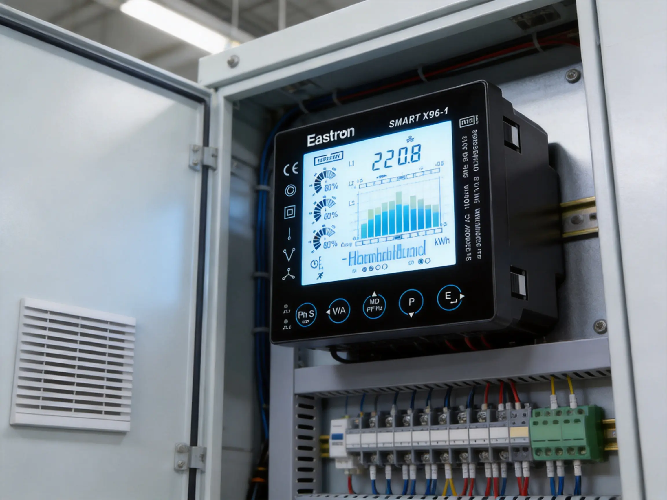
Conventional current-transformer wiring can be time-consuming. Several conductors may need to be terminated individually, polarity must be maintained, and the relationship between each CT and voltage phase must be checked carefully. In retrofit projects, limited panel space can make these tasks even more difficult.
The RJ12 type current connection provides a plug-in alternative for compatible sensors. When used with a three-in-one current sensor and pre-cut wiring loom, the current channels can be connected with fewer separate termination steps. This can reduce installation time and help standardize the wiring process across multiple panels.
A plug-in connection does not eliminate the need for electrical safety procedures. The installation team must still isolate circuits where required, verify the correct sensor rating, confirm polarity, ensure that the connector is fully inserted, and protect communication and measurement wiring from excessive electromagnetic interference. However, a structured connector system can reduce avoidable wiring variation.
The analyzer supports push-in installation and plug-in connection. This is beneficial for panel builders who need to install multiple instruments efficiently. A standard 96 mm panel format allows the device to fit within many existing control-panel layouts, while push-in retention can simplify front-panel mounting compared with arrangements that require several rear fasteners.
Before installation, the panel cut-out, depth, clearance, and terminal accessibility should be checked. The product dimensions are listed as 96 by 96 by 92 mm. The panel designer should allow sufficient rear clearance for voltage terminals, the RJ12 current connection, RS485 wiring, pulse-output wiring, and any required bend radius.
The front display is rated IP51 according to IEC 60529. This provides protection appropriate to a clean, enclosed panel environment, but it should not be interpreted as protection for direct outdoor exposure, water jets, or heavy dust conditions. The complete enclosure and installation environment should be considered when selecting the mounting location.
The analyzer is intended for a 100 mA current input. The current sensor’s primary current rating should be selected according to the maximum expected load and the desired measurement resolution. A sensor that is too small may saturate or be exposed to excessive current, while a sensor that is too large may reduce useful resolution at low loads.
The sensor direction should be consistent with the analyzer’s import and export conventions. In a three-phase system, the phase-current sensors should be installed on the corresponding conductors, and their labels should be recorded in the commissioning documentation. The current signal and voltage reference for each phase must correspond correctly for accurate real and reactive power calculations.
A structured commissioning process can include the following checks:
First, confirm that the system is isolated or otherwise safe to work on according to the site’s electrical procedures. Verify the supply configuration, nominal voltage, frequency, and phase arrangement.
Second, confirm the current-transformer primary ratio and ensure that the analyzer has been configured with the corresponding value. The rated current input is 100 mA, but the displayed primary current depends on the programmed sensor ratio.
Third, verify that the voltage wiring follows the selected 3P3W or 3P4W configuration. Check that the phase labels are consistent throughout the panel drawings, sensor loom, and analyzer terminals.
Fourth, inspect the RJ12 connection, voltage terminals, RS485 conductors, pulse-output wiring, and protective arrangements. Loose or incorrectly inserted connectors can produce intermittent readings or communication faults.
Finally, compare the analyzer readings with a trusted reference instrument under a stable load. Check phase balance, current direction, active power sign, power factor, energy accumulation, and communication data before placing the system into normal operation.
The RS485 interface uses Modbus RTU over a two-wire half-duplex connection. This is a common and practical communication method for industrial automation, building management, energy monitoring, and supervisory control applications.
Available baud rates are 2400, 4800, 9600, 19200, and 38400 bits per second. The device address range is 1 to 247. Parity options include none, even, and odd, with one or two stop bits available. These settings allow the analyzer to match the communication parameters of a wide range of data-acquisition systems.
RS485 is suitable for multi-device networks when the bus is designed correctly. Network planners should consider cable type, maximum cable length, termination, grounding strategy, device addressing, electromagnetic environment, and the number of connected instruments. Each analyzer should have a unique address, and all devices on the same bus should use compatible serial settings.
Modbus RTU enables a central controller to request measurement values and status information from the analyzer. Typical data-collection strategies may include reading voltage, current, active power, reactive power, apparent power, energy, frequency, power factor, and harmonic information at regular intervals. The exact register map and data-format details should be taken from the applicable product documentation when programming a supervisory system.
The analyzer provides pulse outputs for energy-related signaling. The contact rating is specified as 2 to 27 mA at 27 V DC, with a voltage range of 5 to 27 V DC. Pulse width can be selected as 60, 100, or 200 milliseconds.
The configurable pulse constant for S0 output 1 is 0.01, 0.1, 1, 10, or 100 kWh/kVArh. S0 output 2 is identified as 3200 impulses per kilowatt-hour and is non-configurable. These outputs can be connected to compatible pulse counters, data loggers, programmable logic controllers, or building-management equipment.
Pulse outputs are useful when a site has a legacy monitoring system that does not support Modbus. They can also provide a simple independent energy signal for verification. However, pulse wiring should be designed according to the receiving equipment’s voltage, current, isolation, and input requirements.
Modbus and pulse outputs can be used together. For example, Modbus may provide detailed real-time measurements and harmonic data, while a pulse output supplies a simple cumulative energy signal to an existing billing or process-control system.
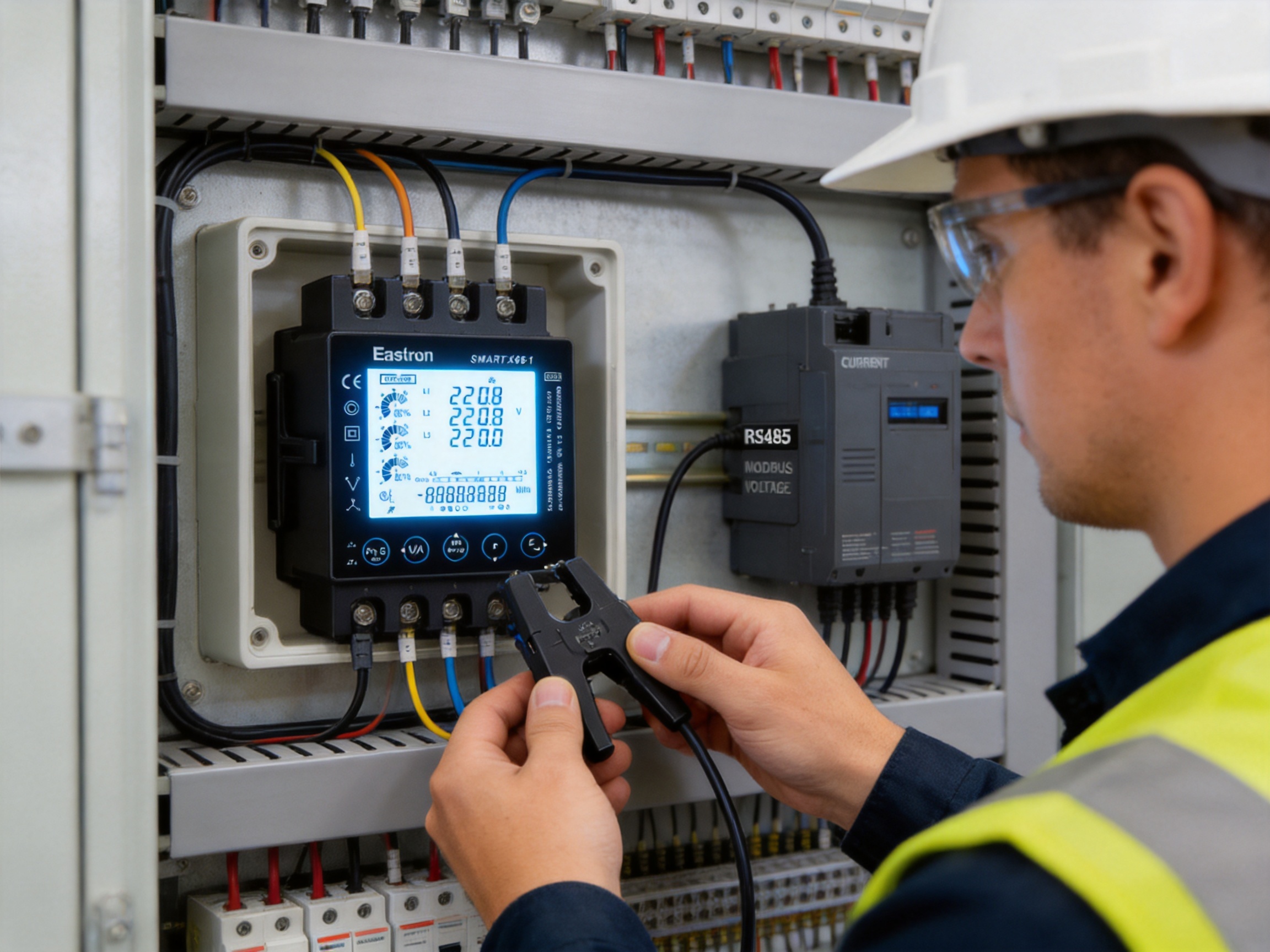
Measurement confidence depends on more than the accuracy of the meter electronics. It also depends on current-sensor characteristics, voltage connections, installation quality, temperature, system waveform, configuration, and the performance of the reference equipment used during verification.
The stated active-energy classifications include IEC 62053-22 Class 0.5S and IEC 62053-21 Class 1.0. These references provide a framework for evaluating energy-meter performance under defined conditions. Reactive energy performance is associated with IEC 62053-24. The inclusion of recognized standards gives users a clearer basis for comparing product specifications and establishing internal acceptance procedures.
Active, reactive, and apparent power accuracy is specified as 1.0% of range maximum. Voltage and current accuracy is specified as 0.5% of range maximum. Frequency accuracy is specified as 0.2% of mid-frequency, and power-factor accuracy is specified as 1% of unity. THD measurement is specified at 2% to the 63rd harmonic.
Engineers should interpret these values using the complete measurement system. For example, if a current transformer has an error that is significant relative to the analyzer input, the combined result will not equal the analyzer’s internal accuracy alone. Similarly, incorrectly matched phase wiring can affect calculated power even if each individual voltage and current channel is within its nominal accuracy range.
For high-value applications, the commissioning plan may include a documented comparison against a calibrated reference meter. The test should cover representative load levels and power factors. If the installation includes nonlinear loads, harmonic readings should be checked under operating conditions that reflect actual site behavior.
The analyzer is specified for an operating temperature range of -25 to 55°C and a storage temperature range of -40 to 70°C. The humidity rating is below 95% relative humidity at 50°C, non-condensing. These specifications make the device suitable for many indoor industrial and commercial environments, including electrical rooms and control cabinets that experience seasonal temperature changes.
The stated pollution degree is 2, and the altitude rating is 2000 meters. These values should be compared with the conditions of the intended installation. If the equipment is installed in a location with conductive dust, corrosive gases, persistent condensation, extreme altitude, or outdoor exposure, additional enclosure and environmental measures may be required.
The meter case uses self-extinguishing UL 94 V-0 material. This material classification supports the use of the device in equipment where resistance to flame propagation is an important design consideration. It does not replace the need for proper panel construction, spacing, protective devices, and compliance with the applicable electrical installation codes.
The listed product weight is approximately 420 grams. The compact 96 by 96 by 92 mm structure allows the instrument to provide a broad measurement feature set without requiring the space of a larger industrial analyzer. The mechanical design is therefore relevant to both new panel construction and retrofit work.
A basic energy meter may provide voltage, current, power, and energy, but it may not offer reactive and apparent power, individual harmonic information, or a visual indication of phase loading. The Smart X96-1A combines these functions in one instrument, reducing the need for separate monitoring devices.
This broader coverage can simplify the design of an energy-monitoring system. Instead of combining several instruments with different interfaces and display formats, a panel builder can use a coordinated analyzer for the main electrical measurements. Fewer devices can also mean fewer panel openings, fewer communication addresses, and less configuration work.
Measurement to the 63rd harmonic is a significant advantage where power quality is important. Many low-cost meters focus on fundamental values or provide only a limited THD indication. A higher-order measurement range can help engineers investigate distortion from modern electronic loads and identify trends that may not be visible in basic monitoring.
The RJ12 current-transformer interface and compatible three-in-one sensor approach can reduce wiring complexity. Compared with individual screw-terminal CT connections, a keyed plug-in arrangement can make repeat installations faster and reduce the chance of mixing phase channels. This is particularly valuable for panel builders producing multiple assemblies or service teams working in crowded retrofit panels.
The backlit LCD provides immediate local information, while RS485 Modbus RTU enables remote access. Some competing solutions may require an external display, an additional communication module, or separate pulse equipment. Combining local and remote functions in the base analyzer can reduce system architecture complexity.
Self-powering from any of the three phases can reduce dependence on an auxiliary supply. This may lower component count and simplify installation, especially in distribution boards where a dedicated control voltage is not available. The actual application must still satisfy the product’s wiring and operating requirements.
The standard 96 mm panel format is familiar to engineers and panel manufacturers. It supports clear visibility, straightforward front-panel replacement, and integration into conventional switchboard designs. The push-in mounting concept can further reduce installation effort.
A measurement instrument is only as reliable as the engineering and manufacturing system behind it. Advanced production is not limited to assembling components. It includes product architecture, sensor-interface design, embedded software, calibration, laboratory verification, traceability, environmental testing, and after-sales support.
The manufacturer behind this analyzer develops electricity meters, power analyzers, current sensors, communication modules, and energy-management systems. This breadth is important because the analyzer’s performance depends on the interaction between measurement electronics, current sensing, communications, and software. Experience across these product categories can support better system compatibility than a company focused on only one component.
Research and development activities are supported by teams in China and the United Kingdom. International development resources can contribute to product localization, standards interpretation, firmware improvement, interface design, and support for different market requirements. Cooperation with universities and technical institutions can also help bring new measurement and communication technologies into commercial products.
The company maintains a professional laboratory capable of EMC, LVD, accuracy, and environmental testing according to IEC, EN, GB, and UL requirements. These test capabilities are valuable because a power analyzer may be exposed to electrical noise, transient conditions, temperature variation, humidity, and installation-specific disturbances. Testing under controlled conditions helps identify weaknesses before products reach the field.
EMC testing is particularly relevant to a device with RS485 communication and harmonic-analysis functions. The analyzer must measure accurately in environments that may contain switching equipment, contactors, drives, transformers, and high-current conductors. Electromagnetic compatibility evaluation helps determine whether the product can maintain stable operation and communication when exposed to defined interference conditions.
Low-voltage directive-related testing and electrical safety verification address insulation, protection, clearances, creepage distances, and other safety characteristics. Accuracy testing evaluates the measurement chain against reference standards. Environmental testing examines operation under temperature, humidity, and related conditions. Together, these activities provide a more complete view of product performance than a single functional test at the end of production.
Modern power analyzers rely heavily on embedded software. The firmware must sample electrical signals, calculate RMS values, determine power quantities, process harmonics, maintain energy registers, manage display functions, control pulse outputs, and respond to Modbus requests. Reliable software development is therefore central to measurement consistency and communication stability.
The manufacturer has experience in software, embedded software, and hardware technologies and holds patented technologies in these areas. Such capabilities can support continued development of measurement algorithms, communication functions, user interfaces, current-sensor integration, and product protection features.
Hardware design is equally important. The analyzer must combine voltage inputs, low-level CT inputs, power-supply circuits, signal conditioning, display electronics, communication interfaces, and output drivers in a compact enclosure. Careful PCB layout and component selection help manage noise, thermal behavior, insulation, and long-term reliability.
An ISO 9001 quality-management system provides a framework for controlled design, purchasing, production, inspection, corrective action, and customer support. For electricity-measurement products, quality management should extend from incoming components to calibration records and final functional verification.
Production control may include inspection of electronic components, automated or guided assembly, soldering-process management, connector checks, firmware loading, display testing, communication testing, insulation checks, and final measurement verification. Calibration and testing procedures should be repeatable so that units meet their stated performance specifications across production batches.
Manufacturing approval or assessment associated with MID standards also indicates experience with regulated metering requirements. While every application must confirm the exact certification and conformity needs for its market, standards-oriented production experience can be valuable for customers working on projects that require documented technical compliance.
Office buildings, retail facilities, hospitals, hotels, and educational campuses often contain multiple distribution boards and diverse electrical loads. The analyzer can be installed at incoming feeders, sub-distribution panels, HVAC systems, lighting circuits, or tenant areas. Modbus data can be collected by a building-management platform to support energy benchmarking and load scheduling.
Factories require visibility into production equipment, motors, welding systems, compressors, pumps, and process lines. Monitoring active power can reveal production demand, while reactive power and power factor can support correction strategies. Harmonic measurements can help investigate the effect of variable-frequency drives and other electronic equipment.
Data centers and technical rooms benefit from continuous monitoring of voltage, current, power, frequency, and energy. Apparent power and phase balance are important for evaluating distribution capacity. Harmonic information can support the assessment of UPS systems, server power supplies, cooling equipment, and auxiliary systems.
Sites with photovoltaic inverters, battery storage, combined heat and power, or other generation assets may experience bidirectional energy flow. Imported and exported energy readings can help distinguish grid consumption from on-site production. Modbus integration allows data from the analyzer to be combined with inverter, battery, and supervisory-system information.
Original-equipment manufacturers and panel builders can integrate the analyzer into switchboards, machine controls, packaged power systems, and energy-monitoring assemblies. The standard panel format, plug-in current connection, local display, and configurable communication settings are useful for repeatable product designs.
Energy auditors often need to install monitoring equipment without making major changes to an existing distribution system. A current-transformer input and compact panel format can support retrofit deployments. The analyzer can collect baseline data, identify load patterns, and help measure the effect of efficiency projects.
The analyzer can operate as a standalone panel instrument, but its greatest value may appear when integrated into a broader monitoring system. A typical arrangement includes current sensors, voltage connections, RS485 cabling, a gateway or data logger, a software platform, and an energy-management dashboard.
At the field level, the analyzer measures electrical quantities and presents them locally. The RS485 network transports selected values to a gateway, programmable controller, supervisory computer, or building-management system. The higher-level platform can store historical records, create trend graphs, calculate energy intensity, generate alarms, and compare different circuits.
System designers should determine the required sampling interval and data-retention period. Fast-changing power-quality events may require a different collection strategy from monthly energy reporting. Harmonic values can generate substantially more data than basic voltage and energy registers, so the communications and database architecture should be planned accordingly.
Alarm logic can be based on voltage limits, current thresholds, power-factor changes, phase imbalance, energy consumption, or harmonic distortion. An alarm does not automatically identify the cause of a problem, but it can direct maintenance attention to a circuit before a minor issue becomes a failure.
Data security and network segmentation should also be considered. RS485 is a field communication technology, and the gateway or supervisory system may connect to an operational network. Proper access control, documented device addresses, backup configuration files, and change management can help preserve the integrity of the monitoring system.
The following table summarizes the principal characteristics provided for the analyzer. Project engineers should consult the applicable product manual for terminal assignments, register definitions, wiring diagrams, and any conditions associated with the stated specifications.
| Category | Characteristic | Specification |
|---|---|---|
| Measurement system | Supported configurations | 3P3W and 3P4W; product description also identifies 1P2W capability |
| Measurement method | Type of measurement | RMS including harmonics on three-phase AC systems |
| Current input | Rated current signal | 100 mA |
| Current input | Maximum programmable current | 9999 A |
| Power accuracy | Active, reactive, and apparent power | 1.0% of range maximum |
| Energy accuracy | Active energy | IEC 62053-22 Class 0.5S; IEC 62053-21 Class 1.0 |
| Energy accuracy | Reactive energy | 1.0% of range maximum to IEC 62053-24 |
| Voltage accuracy | Voltage | 0.5% of range maximum |
| Current accuracy | Current | 0.5% of range maximum |
| Frequency accuracy | Frequency | 0.2% of mid-frequency |
| Power factor | Accuracy and indication | 1% of unity; 0.01 indication reference |
| Power quality | THD and IHD | THD accuracy 2% to the 63rd harmonic |
| Communication | Interface and protocol | RS485, Modbus RTU |
| Communication | Network type | Two-wire half duplex |
| Communication | Baud rates | 2400, 4800, 9600, 19200, and 38400 bps |
| Communication | Address range | 1 to 247 |
| Pulse outputs | Pulse width | 60, 100, or 200 ms |
| Pulse output 1 | Configurable constant | 0.01, 0.1, 1, 10, or 100 kWh/kVArh |
| Pulse output 2 | Constant | 3200 impulses per kilowatt-hour, non-configurable |
| Mechanical | Dimensions | 96 by 96 by 92 mm |
| Mechanical | Weight | Approximately 420 g |
| Mechanical | Front protection | IP51 according to IEC 60529 |
| Materials | Meter case | Self-extinguishing UL 94 V-0 |
| Environment | Operating temperature | -25 to 55°C |
| Environment | Storage temperature | -40 to 70°C |
| Environment | Humidity | Below 95% RH at 50°C, non-condensing |
| Environment | Altitude | Up to 2000 m |
Long-term performance begins with correct installation. The analyzer should be mounted in a suitable enclosure, protected from condensation and excessive contamination, and positioned where the display can be read safely. The panel should provide adequate ventilation and rear clearance without exposing the device to unnecessary heat from power components.
Voltage and current wiring should be checked during scheduled maintenance. Terminal tightness, connector seating, cable insulation, and sensor positioning can change over time because of vibration, thermal cycling, or maintenance work in the same panel.
Communication networks should be documented. Each device address, baud rate, parity setting, stop-bit setting, cable route, and gateway connection should be recorded. A clear network schedule makes it easier to replace an analyzer or troubleshoot a missing device.
Energy registers and configuration parameters should be backed up where the monitoring system permits it. If a meter is replaced, the new device should be configured with the correct CT ratio, wiring mode, communication settings, pulse constants, and display preferences.
Trend data should be reviewed periodically rather than collected without analysis. Changes in phase balance, power factor, harmonic distortion, or apparent power can provide early indications of equipment degradation, process changes, or new loads. Establishing normal operating ranges makes unusual behavior easier to identify.
Electrical measurement projects often involve more than selecting a meter from a catalog. Customers may need help choosing current sensors, determining communication architecture, interpreting accuracy requirements, configuring pulse outputs, or integrating register data into a software platform.
A manufacturer with experience in meters, current sensors, communication modules, and energy-management systems can provide support across these connected areas. This is particularly useful when the analyzer is part of a larger energy-measurement solution rather than a standalone display.
International experience is also valuable. Products supplied across Europe, Asia-Pacific, the Americas, the Middle East, and Africa may need to accommodate different panel conventions, communication practices, standards expectations, and project documentation requirements. Technical support teams that understand these variations can help reduce implementation risk.
After-sales service should include product documentation, wiring guidance, communication assistance, troubleshooting support, and replacement coordination. For industrial customers, the availability of technical assistance can be as important as the initial product specification because monitoring equipment may remain part of the facility infrastructure for many years.
It is a panel-mounted multifunction power analyzer with an RJ12 type 100 mA current-transformer connection, an LCD display, RS485 Modbus RTU communication, and pulse outputs. It measures electrical and energy parameters in AC systems.
The listed configurations include three-phase, three-wire and three-phase, four-wire systems. The product description also identifies single-phase, two-wire measurement capability. The exact wiring arrangement should be selected and configured according to the installation manual.
The analyzer receives a low-level signal from a compatible external current transformer or current sensor rather than carrying the full load current through the meter. This supports safer and more flexible measurement of high-current circuits when the correct sensor ratio is selected.
The RJ12 connection provides a plug-in interface for compatible current sensors. When combined with a three-in-one sensor and pre-cut wiring loom, it can simplify installation, reduce individual termination work, and help maintain consistent phase-channel wiring.
Yes. It supports total harmonic distortion and individual harmonic distortion measurement up to the 63rd harmonic. The stated THD accuracy is 2% to the 63rd harmonic.
The product description states that it measures active and reactive energy, including imported and exported energy. This makes it suitable for systems with distributed generation, storage, or other bidirectional power-flow conditions.
It uses Modbus RTU over a two-wire half-duplex RS485 interface. Baud rates from 2400 to 38400 bps are available, and device addresses range from 1 to 247.
It can be integrated with compatible systems that support RS485 Modbus RTU. The system designer must verify the required register map, data formats, serial settings, cable design, addressing, and gateway compatibility.
Pulse outputs provide energy-related signals to pulse counters, controllers, data loggers, or legacy monitoring equipment. One output has configurable pulse constants, while the second output is identified as 3200 impulses per kilowatt-hour and is non-configurable.
The product is described as self-powered from any of the three phases. A separate auxiliary supply may therefore not be required in a suitable three-phase installation. The actual wiring and operating conditions must be confirmed before installation.
It refers to the front-panel instrument size. This format is widely used in industrial control and distribution panels. The listed overall depth is 92 mm, so rear clearance should be included in the enclosure design.
The front display is specified as IP51 according to IEC 60529. This is suitable for an appropriate enclosed panel environment, but it does not indicate protection against water jets, immersion, or unrestricted outdoor exposure.
Check the voltage wiring configuration, phase sequence, CT ratio, current-sensor direction, phase association, connector seating, and load conditions. Incorrect matching between a current sensor and its corresponding voltage phase is a common cause of incorrect calculated power.
The manufacturer develops meters, power analyzers, current sensors, communication modules, and energy-management systems. It also maintains laboratory capabilities for EMC, LVD, accuracy, and environmental testing, operates under ISO 9001 quality management, and has experience with international standards and regulated metering requirements.
Typical users include panel builders, industrial facilities, commercial-building operators, energy auditors, OEMs, maintenance teams, data-center operators, and sites with renewable generation or energy-storage systems. It is especially useful where local display, remote data access, energy measurement, and harmonic analysis are required together.
The Smart X96-1A combines the functions needed for modern electrical monitoring in a compact panel-mounted instrument. Its support for 3P3W and 3P4W systems, 100 mA CT input, self-powering design, backlit LCD, power bar graph, high-order harmonic analysis, RS485 Modbus RTU, and pulse outputs gives it a broad range of practical uses.
Its strongest advantages are the combination of measurement breadth and installation convenience. The analyzer does more than display voltage and current: it measures active, reactive, and apparent power, energy in both directions, frequency, power factor, THD, and individual harmonics. At the same time, the RJ12 current-sensor interface, three-in-one sensor option, pre-cut wiring approach, and push-in mounting can help panel builders complete installations more efficiently.
The product’s value is reinforced by the manufacturer’s broader capabilities in electricity meters, current sensors, communications, embedded software, hardware development, laboratory testing, quality management, and international technical support. These capabilities are important when an analyzer must operate reliably as part of a complete energy-measurement solution.
For facilities seeking better visibility into energy consumption, load balance, power quality, and remote system performance, a multifunction analyzer with local and digital interfaces can provide a practical foundation. When correctly selected, installed, configured, and maintained, it can support more informed maintenance decisions, more accurate energy analysis, and better management of electrical infrastructure.
1. Product technical information for the Smart X96-1A multifunction power analyzer.
2. IEC 60529, Degrees of protection provided by enclosures.
3. IEC 62053-21, Electricity metering equipment and active energy accuracy requirements.
4. IEC 62053-22, Electricity metering equipment and static meter accuracy requirements for active energy.
5. IEC 62053-24, Electricity metering equipment and static meters for reactive energy.
6. Modbus Application Protocol Specification and Modbus over Serial Line implementation guidance.
7. UL 94, Tests for flammability of plastic materials for parts in devices and appliances.
8. ISO 9001, Quality management systems and requirements.
9. General engineering practices for current-transformer selection, phase identification, energy monitoring, and power-quality assessment.
Your email address will not be published. Required fields are marked *

We develop and produce high performance electricity meters, power analyzers, current sensors, communication modules and management systems.
Address:NO. 52, Dongjin Road, Nanhu, Jiaxing, Zhejiang, China
Copyright @ Eastron Electronic Co., Ltd. All rights reserved
