

 English
 Español
 Deutsch
 中文简体


Product Consultation
Your email address will not be published. Required fields are marked *
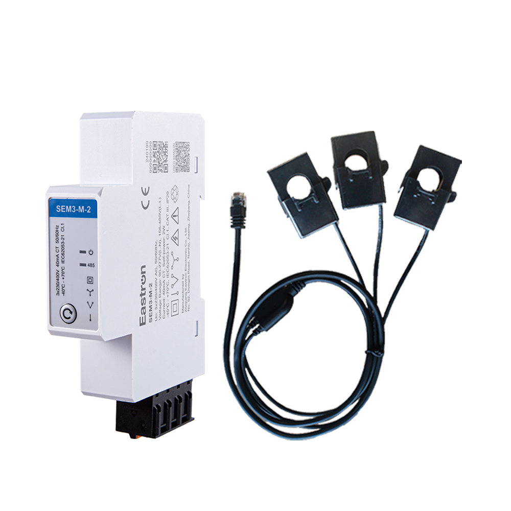
RS485 CT Connection Three Phase Din Rail Energy Meter for PV Metering
May 30,2025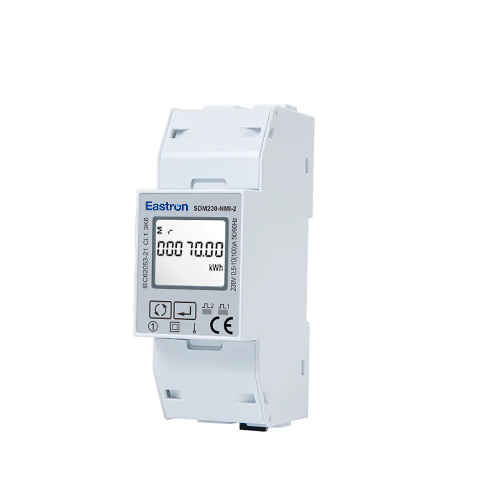
Dual RS485 Din Rail Single Phase Multi-function Solar PV/Zero Export Meter with 50mS Data Update for VPP Solution
Nov 24,2022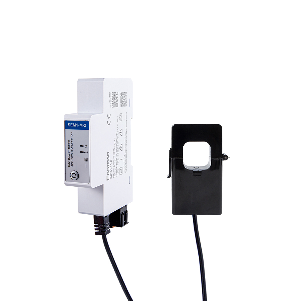
CT Type RS485 Modbus Single Phase Din Rail Energy Meter for PV Metering
May 30,2025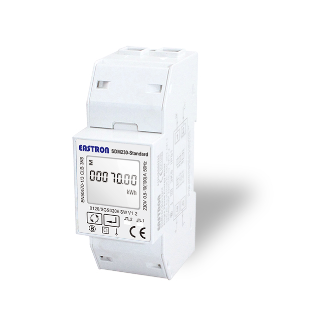
RS485 Modbus Din Rail Single Phase Electronic kWh Meter
Aug 11,2022
Din Rail Dual Channels DC Energy Monitoring Meter for EV Charging Metering
Aug 02,2022
Din Rail DC Energy Monitoring Meter for EV Charging Metering
Aug 02,2022Content

Modern direct-current systems require accurate, dependable, and easily accessible energy data. Electric vehicle charging equipment, battery storage installations, photovoltaic systems, telecommunications power systems, industrial control panels, and DC distribution networks all depend on measurements that can be trusted over long operating periods. Voltage, current, power, and energy must be monitored together so that operators can understand consumption, verify charging performance, detect abnormal operating conditions, and manage energy costs.
The DCM230-2-150 is a DIN rail DC energy meter designed for these requirements. It measures direct-current electrical parameters in systems up to 1000V DC and supports current measurement up to 150A when used with the supplied 75mV DC shunt. The meter provides active energy measurement, power measurement, voltage measurement, current measurement, pulse output, and RS485 communication using Modbus RTU. It also supports bidirectional import and export measurement, making it suitable for applications in which energy can flow in both directions.
Its combination of a compact DIN rail format, external shunt connection, wide voltage range, digital communication, and MID approval gives the meter a strong position in the market for professional DC energy measurement. Instead of being limited to a narrow current range or a single local display, the device can become part of a larger monitoring, billing, charging, or energy-management system.
The DCM230-2-150 is a single-phase DC energy meter intended for direct-current energy systems. Its measurement architecture is based on voltage sensing and current measurement through an external shunt. The supplied shunt produces a nominal 75mV signal at its rated current, and the meter converts that signal into a current value for display, energy calculation, pulse generation, and communication.
The product is rated for DC voltage inputs from 100V to 1000V. This broad operating range allows one meter design to be used in many different applications, from medium-voltage battery and charging systems to high-voltage DC equipment. The maximum current for this version is 150A, while the wider DCM230-2 platform also accommodates other current configurations when matched with the appropriate shunt.
The meter is designed for installation on a DIN rail inside a suitable electrical enclosure. DIN rail mounting simplifies panel construction, allows orderly wiring, and makes it easier to combine the meter with circuit protection, contactors, communication gateways, terminal blocks, and control equipment. For installers, this can reduce the time needed to create a neat and serviceable measurement panel.
Key functions include:
Measurement of DC voltage, current, power, and active energy.
Bidirectional measurement of imported and exported energy.
Operation with a 75mV external DC shunt.
Measurement capability up to 1000V DC.
Maximum current measurement of 150A for the specified version.
RS485 communication with Modbus RTU.
Pulse output for integration with compatible monitoring or counting equipment.
MID approval and compliance with the stated EN50470-4 and IEC62053-41 requirements.
DIN rail installation for electrical distribution and control cabinets.
Low meter power consumption of no more than 0.5W according to the supplied specifications.
The result is a practical measurement device for systems where energy data must be available locally and remotely.
DC power systems are becoming more important in transportation, renewable energy, industrial automation, and data infrastructure. Batteries store energy in DC form. Solar photovoltaic arrays generate DC power. Electric vehicle batteries are charged with DC energy, either directly or through power conversion equipment. Telecommunications systems and many control systems also use DC distribution.
In these systems, measuring only voltage or current is not enough. A battery can maintain an acceptable voltage while its current changes significantly. A charger can operate at the expected voltage while delivering less energy than intended. A solar installation can produce current in one direction during generation and receive energy in the opposite direction during auxiliary operation. Energy measurement brings these individual values together and shows how much electricity is actually being transferred.
Reliable energy data supports several practical decisions. Operators can compare the energy delivered by a charger with the energy received by a battery. Facility managers can allocate consumption to different loads. Service engineers can identify abnormal voltage drops or unusually high currents. Renewable energy operators can distinguish generated energy from exported energy. System designers can also use long-term data to size storage, protection, cooling, and conversion equipment more effectively.
The DCM230-2-150 is particularly suitable when the installation requires more than a simple local indication. Its RS485 Modbus interface makes measured values available to programmable logic controllers, building management systems, supervisory control and data acquisition platforms, industrial computers, and energy management software. This turns the meter from an isolated panel instrument into a data source within a complete electrical monitoring system.
One of the principal advantages of the product is its 100V to 1000V DC input range. Many competing DC meters are designed for a specific nominal voltage, such as 12V, 24V, 48V, 400V, or 600V. A meter with a narrow input range may require replacement when a system is upgraded or redesigned. A wide-range model gives equipment manufacturers and integrators greater flexibility when developing several system versions.
The 1000V DC capability is especially relevant to high-voltage electric vehicle charging equipment, photovoltaic installations, battery energy storage, and industrial DC distribution. Higher system voltage can reduce current for a given power level, which may help reduce cable losses and conductor size. However, high-voltage DC also increases the importance of appropriate insulation, isolation, creepage and clearance, protective devices, enclosure design, and installation procedures. The energy meter should therefore be installed only within a correctly engineered and protected system.
A broad voltage range also simplifies spare-parts management. A service department may be able to use one meter family across several projects instead of keeping separate meters for every nominal DC voltage. This can reduce procurement complexity and provide a more consistent user experience across different equipment models.
The meter’s specified voltage input is intended for measurement and system monitoring. It does not replace fuses, circuit breakers, isolators, contactors, insulation monitoring devices, or other required protection equipment. The voltage connections must be made according to the wiring diagram and the applicable electrical regulations.
The DCM230-2-150 measures current through an external shunt rather than passing the full load current through the meter body. A shunt is a precision low-resistance element that develops a small voltage proportional to the current flowing through it. In this product configuration, the default shunt signal is 75mV.
This approach offers several important benefits. First, the meter itself does not need to carry the entire 150A load through small internal terminals or sensing paths. The high-current connection is made through the appropriately rated shunt, while the meter receives the low-level measurement signal. Second, the arrangement supports flexible current ranges. The same meter platform can be matched with different shunts for different current requirements, subject to the correct configuration and technical documentation.
External shunt measurement can also be advantageous in systems where the high-current conductor must be physically separated from the monitoring electronics. The shunt can be installed in a suitable position within the power circuit, while the DIN rail meter is placed in a protected instrumentation area. This can assist with panel layout and service access.
Correct shunt installation is essential. The shunt must be selected for the required current and 75mV rating, installed with suitable conductor sizes, and connected with the correct polarity. The sense wires should be routed and terminated as specified by the manufacturer. Loose connections, excessive conductor resistance, incorrect polarity, or installation of a shunt with the wrong voltage rating can lead to inaccurate readings or unsafe conditions.
For a 150A system, the shunt and its associated conductors must be treated as high-current components. The installer should verify continuous current, short-time current, temperature rise, enclosure ventilation, mechanical tightening, and protection coordination. The energy meter provides measurement; the complete installation remains responsible for safe current carrying capacity and fault protection.
Energy does not always move in one direction. In a battery storage system, energy may flow from a charger into the battery and later flow from the battery to a load or the grid-side conversion system. An electric vehicle charging installation may need to distinguish charging energy from regenerative or exported energy. A photovoltaic system may import power during low generation and export power when production exceeds local demand.
The DCM230-2-150 supports bidirectional measurement, including import and export energy. This provides a clearer picture of the system than a meter that simply accumulates total energy without direction. Separate directional registers can support energy accounting, tariff analysis, charging verification, and performance evaluation.
Bidirectional measurement is also valuable for testing. During commissioning, engineers can verify whether the current transformer or shunt polarity, voltage reference, and power direction are correctly configured. If the system reports energy in the wrong direction, the wiring can be checked before the equipment enters normal service.
In applications involving billing or contractual energy allocation, the installer should confirm the exact approval, register behavior, sealing requirements, and local regulatory conditions. MID approval supports use in appropriate regulated measurement contexts, but the complete installation and operating arrangement must still meet the requirements of the relevant jurisdiction.
The supplied product information identifies Class 1.0 / B accuracy and provides separate measurement values for the principal electrical parameters. The stated accuracy figures are 1% of maximum range for power and active energy, and 0.5% of maximum range for current and voltage. These values should be interpreted together with the product’s official technical documentation, installation conditions, reference conditions, and applicable standards.
| Parameter | Specified Information | Practical Importance |
|---|---|---|
| DC voltage input | 100–1000V DC | Supports high-voltage DC systems and multiple equipment designs |
| Maximum current | 150A for the specified version | Suitable for medium- and high-power DC circuits when correctly protected |
| Shunt input | 75mV default | Allows current measurement through an external precision shunt |
| Power accuracy | 1% of maximum range | Supports operational monitoring and system performance evaluation |
| Active energy accuracy | 1% of maximum range | Useful for energy accounting and approved measurement applications subject to conditions |
| Current accuracy | 0.5% of maximum range | Helps identify load changes and abnormal current behavior |
| Voltage accuracy | 0.5% of maximum range | Supports voltage supervision and equipment performance checks |
| Communication | RS485 and Modbus RTU | Enables integration with automation and energy management systems |
| Pulse output | Available through the DCM230 output | Provides a simple energy pulse signal for compatible counters and controllers |
| Communication distance | Up to 1000m maximum under suitable conditions | Supports distributed panels and remote monitoring architectures |
Accuracy in a real installation depends on more than the meter specification. The shunt rating, shunt tolerance, wiring quality, voltage connection, temperature, electromagnetic environment, load level, and installation method all influence the final result. For the best performance, the meter should be installed with a correctly matched shunt and tested under conditions close to the intended application.
The product’s Class 1.0 / B designation makes it appropriate for many commercial and industrial monitoring tasks. It offers a practical balance between measurement performance, system integration, and installation cost. When a project requires legally controlled billing, the designer should verify all applicable requirements for the specific country, tariff, sealing arrangement, and metering point.
Digital communication is one of the most valuable features of the meter. The RS485 physical interface is widely used in industrial automation because it can support long cable runs, multiple devices on a bus, and robust communication in electrically demanding environments when correctly installed.
The meter communicates using Modbus RTU. Its documented communication address range is 1 to 247, transmission speeds range from 1200bps to 19200bps, and parity can be set to none, odd, or even. One or two stop bits are available. These settings allow the meter to be matched with a broad range of controllers, gateways, data loggers, and software platforms.
Modbus RTU also reduces dependence on proprietary communication systems. A system integrator can typically read voltage, current, power, energy, and status data using common industrial communication tools. This can make the product easier to include in a project that already contains meters, drives, controllers, or environmental sensors using the same protocol family.
For reliable communication, RS485 wiring should be planned as a proper bus rather than as an uncontrolled star network. Cable routing should avoid unnecessary proximity to high-noise switching conductors. Shielding, grounding, termination, biasing, address assignment, and baud-rate selection should follow the requirements of the complete network. Each connected device must have a unique address.
The maximum communication distance is stated as 1000m. Actual distance depends on cable type, data speed, electrical noise, topology, termination, and the number of connected devices. A shorter, well-terminated network in a controlled cabinet may operate more reliably than a longer network with poor routing or incorrect grounding.
Although Modbus provides detailed digital data, some applications need a simple pulse signal. The DCM230 output includes pulse output in addition to RS485 Modbus communication. A pulse output can be connected to a compatible counter, controller, data acquisition unit, or legacy energy monitoring system.
Pulse-based monitoring can be useful when the receiving equipment does not support Modbus or when a basic energy total is required without implementing a complete digital register map. It can also provide a secondary verification method. For example, a commissioning engineer may compare accumulated pulses with the energy value read over RS485.
The receiving device must be compatible with the pulse characteristics and electrical requirements specified for the meter. The installer should confirm pulse weighting, output type, maximum switching capability, cable length, and input compatibility before connection. Pulse output is not a replacement for the meter’s communication interface when detailed voltage, current, power, directional energy, or diagnostic information is required.
The DIN rail form factor is a major practical advantage over larger panel meters or custom-mounted instruments. Standard DIN rail installation allows the product to be placed alongside protective devices, contactors, terminal blocks, power supplies, gateways, and control relays. This helps create modular electrical panels that can be assembled, tested, and serviced efficiently.
A compact rail-mounted meter can also be installed close to the measurement point while remaining accessible to operators. A clear panel layout makes it easier to identify voltage terminals, shunt connections, communication terminals, and pulse output wiring. Good labeling and separation between power and communication circuits are recommended.
The installation enclosure must provide suitable protection against dust, moisture, accidental contact, vibration, and temperature extremes. The meter should not be installed in a location where condensation, corrosive chemicals, excessive heat, or direct mechanical impact could affect performance. The enclosure design should account for the heat produced by the shunt and other power components, not only the low power consumption of the meter itself.
Before commissioning, the installer should verify the DC voltage range, current direction, shunt rating, polarity, communication settings, address, pulse configuration, protective devices, and terminal tightness. A controlled test at a known load can help confirm that the measured voltage, current, power, and energy direction are sensible.
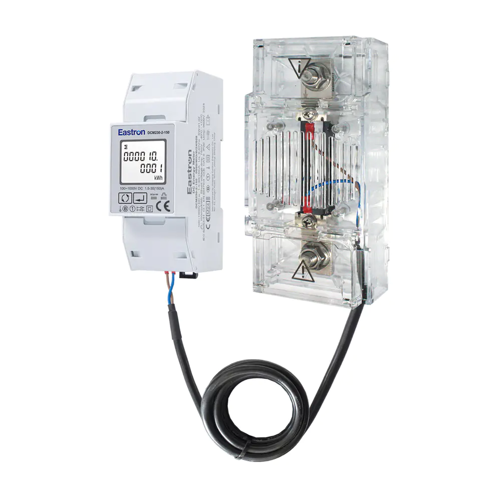
Max. 150A Current RS485 Din Rail DC Energy Meter with DC Shunt
DC energy measurement is important in electric vehicle charging because the operator often needs to know how much energy has been delivered to a vehicle or charging outlet. The meter can measure voltage, current, power, and energy in charging equipment operating within its specified range. Bidirectional measurement can also support systems involving vehicle-to-grid, vehicle-to-building, or other energy-reversal functions when the complete charger architecture permits such operation.
In a charger, the meter may be installed on the DC output side or at another defined measurement point. Its 1000V DC voltage capability is suitable for many modern high-voltage charging designs, while the 150A configuration can serve charging circuits within the corresponding current limit. The external shunt allows the high-current path to be measured without routing the complete load through the meter body.
Charging operators can use the measured data to verify delivered energy, compare sessions, identify abnormal charging behavior, and support maintenance. Through Modbus, the charger controller or a separate backend gateway can collect readings and combine them with session identification, time, vehicle information, and charging status.
Designers should carefully define the measurement point. Energy measured at the charger output may differ from energy drawn from the AC supply because of conversion losses and auxiliary consumption. The meter should therefore be positioned according to the intended commercial, technical, or operational measurement objective.
Battery energy storage systems repeatedly charge and discharge, making directional energy measurement particularly useful. The DCM230-2-150 can measure energy entering or leaving a DC battery bus, subject to the voltage and current ratings of the selected configuration. Operators can monitor charge energy, discharge energy, power peaks, and changes in battery operating conditions.
When connected to an energy management platform, the meter can provide data for charge and discharge scheduling, peak shaving, demand management, renewable energy absorption, and backup power analysis. Historical data can help determine whether a storage system is delivering the expected energy and whether conversion or cable losses are within acceptable limits.
The meter does not replace a battery management system. A battery management system performs functions such as cell supervision, balancing, temperature monitoring, contactor control, and safety protection. The energy meter complements those functions by providing electrical energy data at the selected system measurement point.
Because battery systems may contain high fault currents, the shunt, busbars, cables, fuses, contactors, and enclosure must be designed by qualified professionals. The energy meter and shunt should be installed only after the system designer has verified insulation, isolation, creepage, clearance, short-circuit withstand, and service procedures.
Photovoltaic panels generate DC energy before an inverter converts it into AC power. Measuring the DC side can help operators understand array output, compare strings or combiner groups, assess conversion efficiency, and identify degradation or faults. In systems with battery storage, the meter can also help distinguish solar energy sent to storage from energy discharged later to a load.
The broad voltage range is useful because photovoltaic array voltage varies according to module arrangement and system architecture. However, the design must remain within the meter’s specified input range under the highest possible open-circuit voltage and the expected environmental conditions. The system designer must also consider cold-weather voltage increases, switching transients, insulation, and DC arc hazards.
Bidirectional measurement can be used where a DC bus receives power from more than one source or where storage causes energy to reverse direction. This allows the monitoring system to separate generated, stored, consumed, and exported energy more effectively than a one-direction counter.
Industrial DC distribution systems often include rectifiers, batteries, control equipment, motors, instrumentation, and auxiliary loads. A meter installed at a distribution point can show how much current is being used and whether voltage remains stable as loads change. RS485 communication makes it possible to collect data from multiple cabinets and present it through a central supervisory interface.
Telecommunications installations also use DC power systems with rectifiers and battery backup. Monitoring the DC bus can help maintenance teams observe load current, battery charging behavior, and energy consumption. When many remote sites are involved, digital communication reduces the need for local inspection and can support centralized alarm and performance reporting.
In both industrial and telecommunications environments, the meter should be integrated with the site’s alarm strategy. A controller may generate warnings when voltage falls below a threshold, current exceeds an expected value, or energy flow reverses unexpectedly. The meter supplies the measurement data, while the control system determines the appropriate response.
Basic DC meters may provide only local voltage and current indication. Such instruments can be adequate for simple systems, but they may not satisfy the requirements of modern energy management. The DCM230-2-150 offers several advantages over a basic display-only instrument.
First, it measures energy as well as instantaneous electrical quantities. Energy values are needed for charging verification, consumption analysis, and cost allocation. Second, it supports bidirectional import and export measurement, which is important for storage and renewable applications. Third, RS485 Modbus communication allows data to be transferred to remote software instead of requiring an operator to read the display manually.
The external shunt design is another advantage over meters with a fixed internal current path. It allows high current to be measured through a purpose-selected component and offers greater flexibility in panel layout. The 1000V DC voltage range also makes the product suitable for more demanding systems than low-voltage-only meters.
MID approval and the stated standards provide additional confidence for projects that require documented measurement performance. Approval does not eliminate the need for correct installation or local compliance, but it distinguishes the product from unverified instruments intended only for approximate indication.
Some DC meters are optimized for one nominal voltage or one current range. These products may work well in their intended application but can create difficulties when a system is expanded or redesigned. A meter capable of up to 1000V DC and 150A in the specified configuration offers greater design latitude.
Other solutions depend on a proprietary communication protocol or a dedicated software platform. The use of Modbus RTU provides a more accessible integration path for equipment manufacturers and system integrators. It allows the meter to be incorporated into existing industrial networks and reduces dependence on one supervisory software supplier.
A further advantage is the combination of pulse output and digital communication. A project can use Modbus for detailed data and a pulse signal for a simple secondary counter or legacy controller. This dual-interface approach can help support different levels of system complexity within the same product family.
The product is manufactured by Eastron Electronic Co., Ltd., a high-tech electricity product and energy measurement solutions company headquartered in Jiaxing, China. The company develops and produces electricity meters, power analyzers, current sensors, communication modules, and energy management products. Its location near Shanghai, Hangzhou, and Jiangsu provides access to a substantial electronics manufacturing and engineering environment.
The company’s stated product development strengths include teams in China and the United Kingdom, cooperation with universities and institutions, and continued investment in new technologies for electrical measurement. For a product such as the DCM230-2-150, this type of engineering structure is important because a reliable meter requires more than a display and a communication chip. It requires coordinated development of measurement circuits, embedded software, mechanical housing, calibration methods, communication functions, and compliance documentation.
Eastron reports that it operates a professional laboratory capable of EMC, low-voltage directive, accuracy, and environmental testing according to IEC, EN, GB, and UL standards. These capabilities are significant because energy meters are exposed to several types of technical risk. Electromagnetic compatibility testing evaluates whether the product can operate correctly in the presence of electrical interference and whether it creates unacceptable interference. Accuracy testing verifies measurement performance. Environmental testing helps assess operation under conditions such as temperature and humidity variations.
In-house or controlled laboratory testing can also improve the feedback cycle between design and production. When an engineering team can evaluate accuracy, electromagnetic performance, and environmental behavior during development, it can identify weaknesses before a product reaches large-scale production. This supports more consistent product improvements and helps maintain a documented approach to compliance.
The company also states that it holds patented technologies in software, embedded software, and hardware and has been recognized as a High-tech Enterprise and High-tech Research and Development Centre of Electricity Application. These strengths indicate a focus on both hardware design and the firmware that controls measurement, display, storage, pulse generation, and communication.
For customers, the value of this manufacturing background is not limited to the product’s nominal specifications. It also affects technical support, product continuity, customization potential, documentation quality, and the ability to address unusual application requirements. A supplier with experience across meters, sensors, communication products, and management systems can better understand how a meter functions within a complete energy measurement solution.
The company reports following the ISO 9001 quality management system. A structured quality system can support controlled design changes, supplier management, production records, inspection procedures, corrective actions, and traceability. These processes are particularly important for measurement products because a small change in a sensing component, circuit board, calibration method, or firmware routine can affect the result seen by the user.
The product information identifies MID approval and states compliance with EN50470-4 and IEC62053-41. MID approval is relevant to measuring instruments placed on the European market for certain regulated applications. EN50470-4 relates to static meters for active energy and includes requirements associated with accuracy and testing. IEC62053-41 addresses static meters for active energy on direct-current systems.
Standards and approvals should always be verified against the current product certificate, model designation, rated configuration, and intended use. A product family may include several variants, and approval conditions may apply to particular ranges or configurations. Customers requiring legal metrology should request the applicable documentation and confirm the complete installation requirements before specifying the meter for billing.
Compliance testing is also valuable for non-billing installations. It provides an independent technical framework for evaluating accuracy, electromagnetic performance, environmental behavior, and safety-related characteristics. This can make procurement and project approval easier, especially when a system integrator must document the suitability of each major component.
Before selecting the meter, the engineer should confirm the nominal and maximum DC voltage, expected continuous current, overload profile, shunt rating, energy flow direction, measurement point, communication architecture, and environmental conditions. The 150A version should not be used above its specified current capacity, and the selected shunt must be compatible with the meter’s 75mV input.
The voltage measurement circuit should be protected and wired in accordance with the manufacturer’s diagram and local regulations. The high-voltage DC circuit must include suitable isolation and protective devices. The meter’s low power consumption does not mean that the installation is low risk; the measured circuit may contain dangerous and potentially lethal voltage and energy.
The shunt should be installed where it can dissipate heat safely and where its terminals can be protected against accidental contact. Its polarity should be marked clearly. If the project requires import and export registers to have a particular meaning, the designer should define the positive energy direction during commissioning and document it for maintenance personnel.
For communications, the system designer should prepare a register map and decide which values are read cyclically, which are recorded historically, and which generate alarms. Polling too many devices too rapidly can reduce network performance. A practical communication plan normally includes device addresses, baud rate, parity, stop bits, cable type, termination, gateway location, and data logging interval.
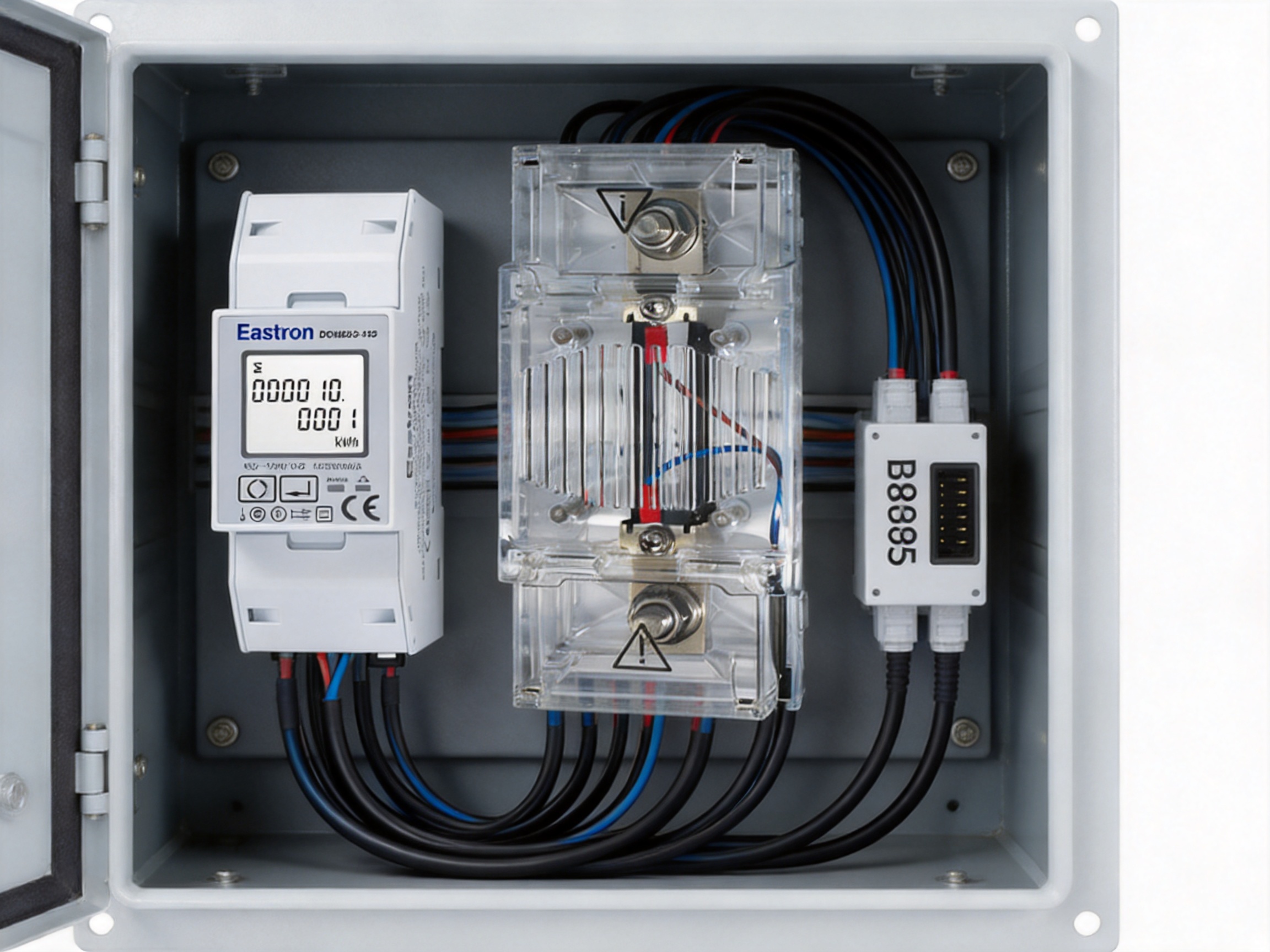
A structured commissioning process helps ensure that the meter provides meaningful data from the first day of operation. The first stage is a visual inspection. Check that the meter, shunt, terminals, enclosure, rail mounting, labels, and protective barriers are in good condition. Confirm that the product model and shunt rating match the project documentation.
The second stage is a de-energized wiring inspection. Verify voltage polarity, shunt polarity, sense-wire connections, pulse output wiring, RS485 A and B connections, and protective devices. Confirm that power conductors are tightened to the specified torque and that communication wiring is separated from high-current switching conductors where practical.
The third stage is a controlled energization. Apply voltage within the specified range and observe the meter for abnormal indications. Confirm that the displayed voltage is consistent with a calibrated reference instrument. At a stable load, compare the indicated current and power with expected values. If the reading is negative when positive flow is expected, check the direction of the shunt and voltage reference.
The fourth stage is communication testing. Assign a unique Modbus address, set the required baud rate and parity, and read selected registers from the supervisory controller. Confirm that voltage, current, power, active energy, and directional values are interpreted correctly. If pulse output is used, compare the number of received pulses with the expected energy accumulation.
The final stage is documentation. Record the meter serial number, shunt information, configuration settings, test results, installation date, communication address, and measurement direction. This information can significantly reduce troubleshooting time during future service work.
Electronic energy meters generally require little routine maintenance when installed in a suitable enclosure. Nevertheless, periodic inspection is recommended. Operators should check for loose terminals, discoloration, abnormal heat, corrosion, communication errors, unexpected energy direction, and changes in measurement behavior.
The shunt and high-current connections deserve particular attention. Thermal cycling and vibration can gradually affect terminal tightness. Any sign of overheating, discoloration, damaged insulation, or mechanical movement should be investigated by qualified personnel. Maintenance must follow safe isolation procedures because the DC circuit may remain energized or store energy in capacitors and batteries even after the main source is disconnected.
Communication logs can provide an early indication of problems. Repeated timeouts may result from incorrect addressing, poor termination, electrical noise, damaged cables, or a failed gateway. Sudden changes in energy readings may indicate a wiring issue, a changed load profile, a shunt problem, or a configuration error rather than a failure of the meter itself.
Where the meter is used for regulated measurement, inspection and verification should follow the applicable legal metrology requirements. Calibration intervals, sealing, access control, and records may be prescribed by the project or local authority.
Original equipment manufacturers can benefit from using a meter platform that combines measurement, communication, and approval features in one product. The DCM230-2-150 can be incorporated into charger cabinets, storage systems, renewable energy equipment, DC distribution boards, and industrial power units without requiring a separate voltage meter, current meter, energy counter, and communication module.
The common DIN rail format can simplify mechanical design. Modbus RTU allows the equipment controller to retrieve data using a familiar industrial protocol. The external shunt separates the high-current path from the meter body and allows the designer to select a suitable current arrangement. The wide voltage range supports product families intended for different DC bus voltages.
System integrators can also standardize their software interface around a consistent set of electrical measurements. A central platform may collect data from multiple meters, calculate energy balances, create alarms, and generate reports. This supports scalable projects in which a single installation contains several charging outlets, battery cabinets, solar arrays, or DC distribution branches.
The specified voltage input range is 100V to 1000V DC. The complete installation must remain within the permitted range under normal operation and foreseeable system conditions. Appropriate protection, isolation, and enclosure design are required.
The specified version supports a maximum current of 150A when used with the appropriate external DC shunt. The shunt and all high-current conductors must be rated for the application.
Yes. The product information states that the package includes one DC shunt. The default shunt signal is 75mV. The exact shunt rating and supplied configuration should be confirmed when ordering.
Yes. The meter supports bidirectional measurement for import and export energy. Correct polarity and commissioning are necessary to ensure that the directional registers correspond to the intended power-flow definitions.
The meter uses RS485 physical communication with Modbus RTU. The documented address range is 1 to 247, and communication speeds range from 1200bps to 19200bps. Parity can be set to none, odd, or even, with one or two stop bits available.
The stated maximum transmission distance is 1000m. Actual performance depends on cable quality, transmission speed, topology, termination, grounding, electrical noise, and the number of devices on the network.
Yes. The DCM230 output includes pulse output in addition to RS485 Modbus communication. The receiving equipment must be compatible with the pulse specifications and electrical requirements.
It is designed for DC energy measurement and is suitable for many electric vehicle charging applications that fall within its voltage, current, shunt, environmental, and installation requirements. The measurement point should be selected according to whether the project needs to measure charger output, battery-side energy, or another defined location.
Yes. Its high-voltage DC range, external shunt, bidirectional measurement, and communication functions make it suitable for many battery energy storage applications. It complements, but does not replace, a battery management system and dedicated safety controls.
No. MID approval is an important qualification, but billing use also depends on the exact model and configuration, the applicable certificate, installation requirements, sealing, verification, local regulations, and the defined measurement point. These conditions should be confirmed before use in a regulated billing application.
The supplied information identifies Class 1.0 / B accuracy. It also lists 1% of maximum range for power and active energy and 0.5% of maximum range for current and voltage. Actual performance depends on the shunt, wiring, operating conditions, temperature, load, and installation quality.
The product is designed to use an external DC shunt for current measurement. The high-current circuit should pass through the correctly rated shunt, while the meter receives the shunt’s low-voltage measurement signal. Wiring must follow the official diagram.
No. The energy meter is a measurement and communication device. It does not replace fuses, circuit breakers, isolators, contactors, insulation monitoring equipment, or other required protection components.
Confirm the DC voltage range, maximum current, shunt rating, required energy direction, measurement point, communication settings, pulse requirements, installation environment, approval needs, and local compliance requirements. Also confirm the exact product variant and supplied accessories.
The DCM230-2-150 is a flexible DC energy measurement solution for applications requiring more than a basic voltage or current display. Its 1000V DC input range, 150A current capability with an external 75mV shunt, bidirectional energy measurement, RS485 Modbus communication, pulse output, DIN rail installation, and MID approval make it suitable for a wide range of professional systems.
Compared with narrow-range or display-only meters, it provides greater integration potential and more complete energy information. It can support electric vehicle charging, battery storage, photovoltaic systems, telecommunications infrastructure, industrial DC distribution, and other high-voltage DC applications. The external shunt design separates the high-current path from the measurement electronics and provides flexibility for system layout.
The manufacturer’s engineering resources, laboratory testing capabilities, ISO 9001 quality management approach, standards experience, and international technical teams further support the product’s role in demanding energy measurement projects. As with any high-voltage electrical device, the final performance depends on correct selection, shunt installation, protection, wiring, commissioning, and maintenance.
For equipment manufacturers, panel builders, system integrators, and energy operators, the meter offers a practical way to make DC energy visible, communicable, and actionable. When properly specified and installed, it can provide the measurement foundation needed for safer operation, better energy management, clearer performance analysis, and more reliable long-term system control.
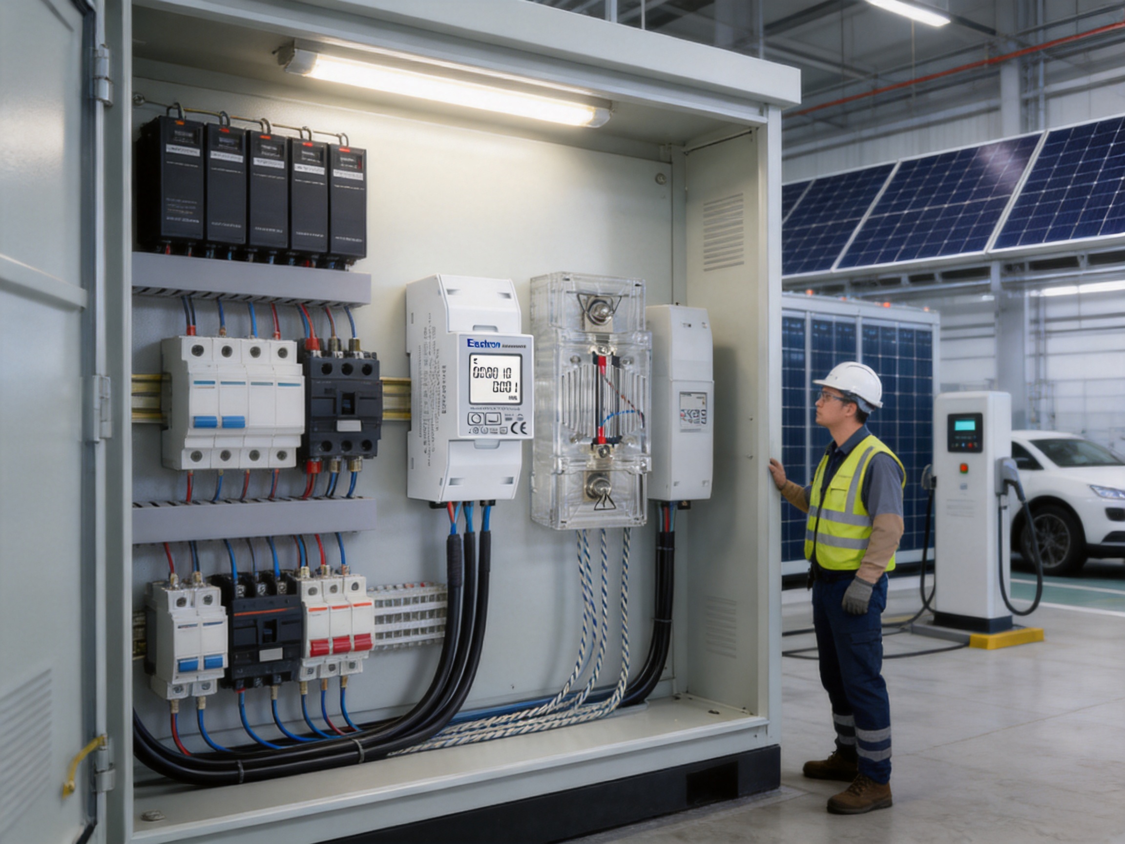
1. Product technical information for the DCM230-2-150 DC energy meter, including voltage range, shunt input, measurement functions, accuracy information, communication settings, and application data.
2. Manufacturer information for Eastron Electronic Co., Ltd., including company capabilities, laboratory facilities, quality management, product development activities, and energy measurement solutions.
3. EN50470-4, Electricity Metering Equipment for Alternating Current, relevant requirements and testing principles for static meters where applicable to approved energy measurement equipment.
4. IEC62053-41, Electricity Metering Equipment, static meters for active energy on direct-current systems.
5. EU Directive 2014/32/EU, requirements relating to measuring instruments and regulated measurement applications.
6. General industrial practices for RS485 serial communication and Modbus RTU network installation.
7. General electrical engineering practices for DC shunt selection, high-voltage DC protection, DIN rail panel construction, and energy monitoring system commissioning.
Your email address will not be published. Required fields are marked *

We develop and produce high performance electricity meters, power analyzers, current sensors, communication modules and management systems.
Address:NO. 52, Dongjin Road, Nanhu, Jiaxing, Zhejiang, China
Copyright @ Eastron Electronic Co., Ltd. All rights reserved
