

 English
 Español
 Deutsch
 中文简体


Product Consultation
Your email address will not be published. Required fields are marked *
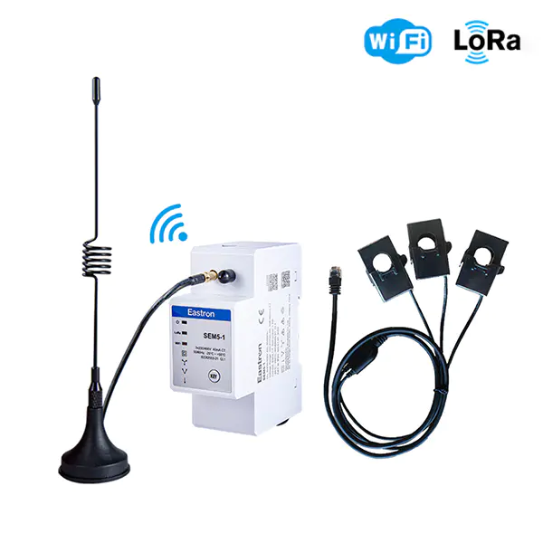
Wifi & LoRa Three Phase Din Rail Energy Meter for PV Metering
Sep 19,2025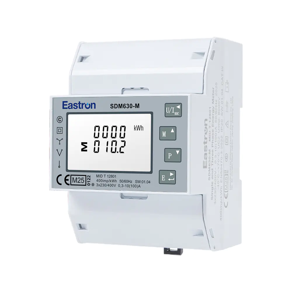
MID UL Certified Din Rail Three Phase Multi-function Energy Meter for EV Charging Metering
Aug 02,2022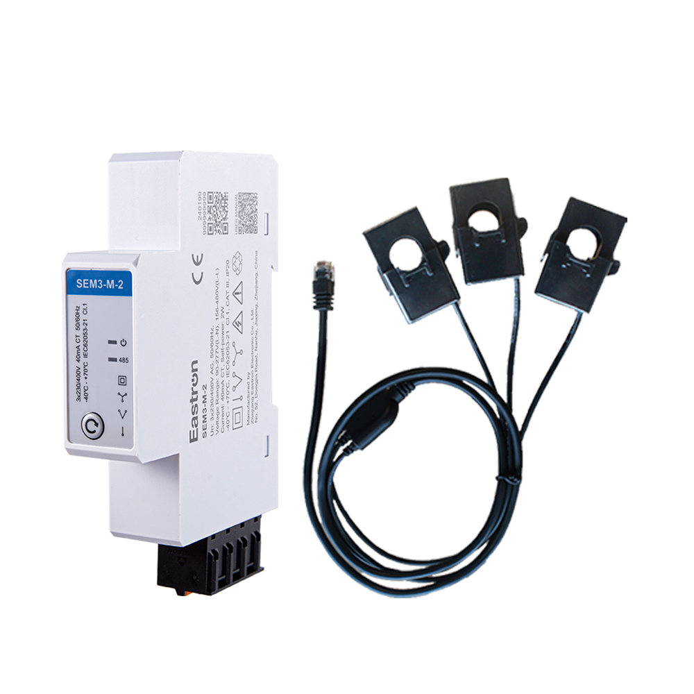
RS485 CT Connection Three Phase Din Rail Energy Meter for PV Metering
May 30,2025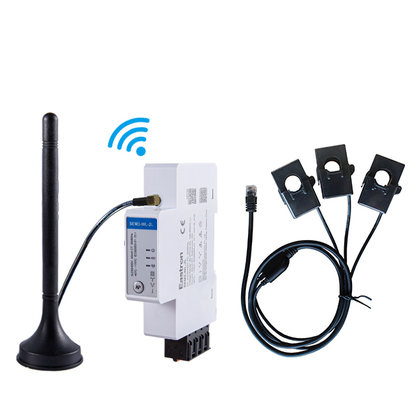
CT Type Three Phase Din Rail Wifi Energy Meter for PV Metering
May 30,2025
MID & UL Approved Three Phase Din Rail Type Multi-function Energy Meter for EV Charging Metering
Nov 24,2022
MID/UL CT Type Din Rail Three Phase Multi-function Energy Meter for EV Charging Metering
Nov 24,2022Content
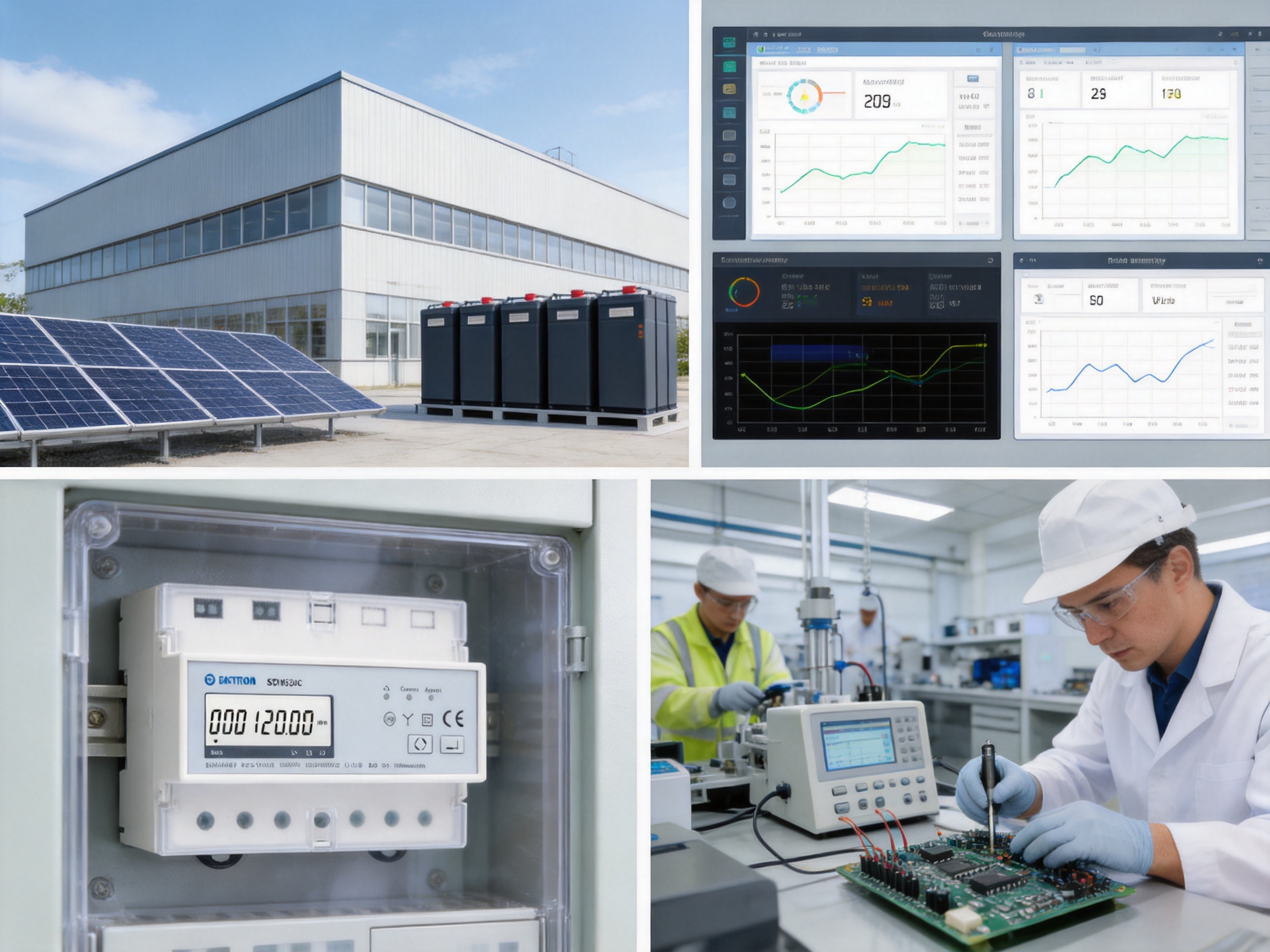
Modern electrical installations require more than a simple record of accumulated energy. Commercial buildings, industrial facilities, distributed energy systems, infrastructure projects, and managed residential developments increasingly need accurate measurement, remote communication, alarm management, and dependable load control in one compact device. The three-phase DIN-rail multifunction energy meter described in this article is designed to meet these requirements through a combination of multifunction measurement, built-in relay control, pulse output, and RS485 Modbus RTU communication.
Designed for three-phase, four-wire AC systems, the meter supports applications requiring current, voltage, power, frequency, power factor, and active or reactive energy information. Its compact DIN-rail format allows it to be installed inside distribution boards, control cabinets, metering panels, and energy management enclosures without occupying the space required by larger panel-mounted instruments.
The product is particularly suitable for automatic meter reading, advanced metering infrastructure, post-pay systems, remote load management, sub-metering, and energy management platforms. By combining measurement and switching functions, it can reduce the number of separate components required in an installation while giving operators more visibility and control over connected loads.
Energy management has developed from periodic manual meter reading into a continuous process based on real-time or scheduled data collection. Facility operators want to understand not only how much energy a site consumes, but also when consumption occurs, which circuits are responsible, whether voltage and current remain within acceptable limits, and whether a load should be disconnected under defined conditions.
A conventional energy meter may provide accumulated kilowatt-hours, but it may not provide enough information for diagnosis or optimization. A multifunction energy meter can show the electrical conditions behind the energy total. Measurements such as phase current, line or phase voltage, active power, reactive power, frequency, and power factor help users identify overloaded circuits, poor power factor, phase imbalance, abnormal voltage, and unexpected operating conditions.
Remote communication adds another layer of value. When meters are connected through an RS485 network, a supervisory system can collect data from many points without requiring personnel to visit each location. Meter values can be transmitted to a building management system, industrial control platform, data logger, energy management software package, or customized monitoring application.
The built-in relay extends the function beyond observation. Authorized users can switch the supply remotely, while configured alarm conditions can initiate automatic disconnection. This capability is useful where energy access must be controlled, where loads need to be managed during abnormal conditions, or where a system operator needs an integrated solution for remote service and recovery.
The meter is a three-phase DIN-rail multifunction energy meter intended for three-phase, four-wire AC systems. It supports a maximum current of 100 A and is suitable for installations where direct-connected measurement and remote control are required. The product combines metering, communication, alarm processing, pulse output, and relay switching in a single enclosure.
The device measures RMS values on a three-phase AC system with neutral. It can measure electrical quantities including current, voltage, power, frequency, power factor, imported energy, and exported energy. These functions make it appropriate for both consumption monitoring and applications in which energy may flow in more than one direction.
An RS485 interface using Modbus RTU enables connection to a master controller or data acquisition network. The communication address can be configured from 1 to 247, allowing multiple meters to operate on a common bus when the installation is properly designed. Selectable baud rates, parity settings, and stop-bit options support integration with a wide range of industrial communication equipment.
The product also provides an energy pulse output for connection to a pulse counter, logger, controller, or legacy energy monitoring system. A pulse interface can be useful when only energy accumulation is required or when a site uses a separate data collection system that does not communicate directly through Modbus.
The built-in relay is designed for remote power control. Through Modbus communication, an operator or control system can switch the connected supply on or off. The relay can also respond automatically to alarm conditions such as over-current or voltage-related events, depending on the configured operating logic. Each phase can be controlled together or separately where the installation and application require this capability.
• Three-phase, four-wire RMS measurement.
• Maximum current capacity of 100 A.
• Active energy accuracy according to IEC 62053-22 Class 0.5s.
• Reactive energy measurement according to IEC 62053-23 Class 2.
• Built-in relay for remote switching and alarm response.
• Measurement of current, voltage, power, frequency, and power factor.
• Import and export energy measurement.
• Energy pulse output.
• RS485 Modbus RTU communication.
• Up to 26 configurable alarm values.
• DIN-rail mounting for compact electrical panels.
• Optional multi-tariff version.
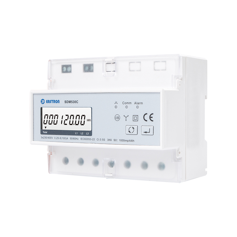
Three Phase Din Rail Multi-function Energy Meter for AMR/AMI
Accuracy is one of the most important considerations when selecting an energy meter. A device used for energy management must provide dependable data over time, across changing loads, and under normal variations in voltage and frequency. The meter’s active energy performance is specified as IEC 62053-22 Class 0.5s, making it suitable for demanding sub-metering and energy measurement applications where data quality is important.
The Class 0.5s designation applies to active energy measurement and indicates a high level of accuracy under the conditions defined by the relevant standard. It is especially valuable for commercial and industrial users who use energy data to allocate costs, evaluate equipment performance, compare production areas, or verify savings after an efficiency project.
Reactive energy is measured according to IEC 62053-23 Class 2. Reactive energy information helps users understand the non-working component of electrical demand and can assist with power factor management, capacitor bank evaluation, and network analysis.
Current and voltage measurement accuracy is specified at 0.5 percent of the range maximum. Power measurement is also specified at 0.5 percent of range maximum, while frequency accuracy is 0.2 percent of mid-frequency. Power factor accuracy is specified at 1 percent of unity, with a resolution of 0.01. Together, these specifications provide a practical measurement foundation for operational monitoring and energy analysis.
| Parameter | Specification |
|---|---|
| Measurement system | RMS measurement on a three-phase, four-wire AC system |
| Active energy | IEC 62053-22 Class 0.5s |
| Reactive energy | IEC 62053-23 Class 2 |
| Power | 0.5% of range maximum |
| Current | 0.5% of range maximum |
| Voltage | 0.5% of range maximum |
| Frequency | 0.2% of mid-frequency |
| Power factor | 1% of unity, resolution 0.01 |
Accurate measurement is also valuable because it improves the quality of decisions made by an energy management system. If the reported values are inconsistent, operators may respond to problems that do not exist or overlook issues that require attention. A dependable meter helps establish a trusted information layer between the electrical installation and the software used to manage it.
The product is specified with a rated current of 5 A, a maximum current of 100 A, a minimum current of 0.25 A, and a starting current of 20 mA. This range allows the meter to detect and record low-level consumption while also supporting higher-current direct-connected applications within the stated maximum.
The rated voltage is 230 V, with an operational voltage range of 80 percent to 120 percent of the rated voltage. This operating range provides tolerance for normal supply variation while maintaining the meter’s ability to monitor the installation. The three-phase, four-wire arrangement is widely used in commercial distribution systems, small industrial facilities, mixed-use buildings, workshops, and many other low-voltage applications.
Before installation, the electrical designer or qualified installer should verify the applicable current, voltage, wiring, protection, isolation, and local code requirements. The 100 A maximum should not be treated as a substitute for a system-specific design review. Conductor sizing, upstream protection, enclosure temperature, terminal capacity, short-circuit conditions, and the switching duty of the relay must all be considered in the complete installation.
The meter’s ability to measure each phase separately is important in systems where phase imbalance can affect equipment performance. A facility may have a balanced total load while individual phases experience different current levels. Per-phase information allows maintenance personnel to redistribute single-phase loads, investigate heating, and improve the use of available capacity.
One of the product’s strongest differentiating features is its built-in relay. Many energy meters measure and communicate but require a separate contactor, relay module, or control device to disconnect a load. By incorporating a relay into the meter, this product can simplify system architecture and reduce the number of separate control components in suitable applications.
Through the RS485 Modbus connection, a central system can issue a command to switch the power supply. This function can support remote connection, disconnection, service activation, demand management, scheduled control, and post-pay operation. It can also reduce the need for site visits when a user or circuit must be enabled or disabled.
The relay can respond to alarm conditions, including over-current or voltage-related events. If an abnormal condition is detected, the relay may open automatically according to the configured protection or control logic. This provides an additional response layer between measurement and physical action.
Another useful feature is the possibility of controlling the relay associated with each phase together or separately. The appropriate control method depends on the electrical design and application. In a coordinated three-phase installation, simultaneous switching may be required. In other systems, phase-specific control may provide greater flexibility. The switching arrangement should always be evaluated against the load type, safety requirements, fault conditions, and applicable regulations.
The relay is particularly useful in post-pay systems. A service provider or facility manager can monitor consumption remotely and control access to a supply through an authorized software platform. Similar functions can be applied to temporary facilities, managed accommodation, commercial units, equipment rental, charging infrastructure, and remote technical installations.
An integrated relay can reduce panel complexity because measurement and switching functions are located in one coordinated product. It can reduce wiring between separate modules and simplify the relationship between an alarm value and the resulting control action. It may also reduce the time required for commissioning because the communication system can address both measurement data and relay status through the same device.
However, the relay must be selected and installed within its electrical rating and intended duty. Highly inductive, high-inrush, or motor-driven loads may require additional switching equipment or protective components. A qualified professional should confirm whether an external contactor is necessary for the specific load.
The product supports 26 alarm values, providing a flexible way to identify abnormal electrical conditions. Alarm thresholds can be used to monitor quantities such as current, voltage, power, frequency, or other available measurement parameters, depending on the configured register and operating logic.
Alarm functionality changes the meter from a passive data source into an active monitoring device. Instead of waiting for an operator to inspect a dashboard, the system can identify a limit violation and generate a response. The response may include a relay action, an event record, a notification through the supervisory system, or a maintenance task.
Over-current monitoring can help identify overloaded circuits, unexpected equipment operation, or wiring problems. Over-voltage and under-voltage monitoring can help protect sensitive equipment and identify supply quality problems. Frequency and power-related alarms may provide useful information in generator systems, isolated networks, or industrial processes.
Alarm thresholds should be configured carefully. A limit set too close to normal operating variation may create nuisance events, while a limit set too high may delay a useful response. Operators should consider start-up currents, short-duration fluctuations, seasonal loading, process cycles, and the response time of connected equipment.
When alarms are connected to relay control, a clear operating philosophy is essential. The installation should define which conditions cause immediate disconnection, which conditions create a warning only, how the system is reset, and who is authorized to restore power. These decisions should be included in commissioning documentation and operating procedures.
RS485 is widely used in industrial and building automation because it supports reliable serial communication over comparatively long distances and can connect multiple devices on a shared bus. The meter uses RS485 Modbus communication for remote setting and reading.
The communication address can be configured from 1 to 247. The transmission distance is specified up to 1,000 meters under appropriate installation conditions. Available baud rates range from 1,200 bps to 9,600 bps, with selectable parity settings of none, odd, or even and one or two stop bits.
| Communication Item | Available Specification |
|---|---|
| Protocol | Modbus RTU |
| Physical interface | RS485 |
| Address range | 1 to 247 |
| Maximum transmission distance | Up to 1,000 m |
| Baud rate | 1,200 bps to 9,600 bps |
| Parity | None, odd, or even |
| Stop bits | 1 or 2 |
For reliable communication, the RS485 network should be installed using suitable twisted-pair cable, correct polarity, appropriate termination, and proper routing away from strong sources of electromagnetic interference. The number of devices, cable length, baud rate, grounding approach, and isolation arrangements should be considered together.
Modbus integration allows a host system to read instantaneous values, accumulated energy, alarm status, relay status, and other supported registers. It can also provide remote configuration and relay control when the relevant permissions and system logic are in place.
The use of a common industrial protocol is a competitive advantage because it avoids dependence on a proprietary communication ecosystem. System integrators can often connect the meter to existing programmable logic controllers, gateways, supervisory systems, or energy management platforms using established Modbus tools and practices.
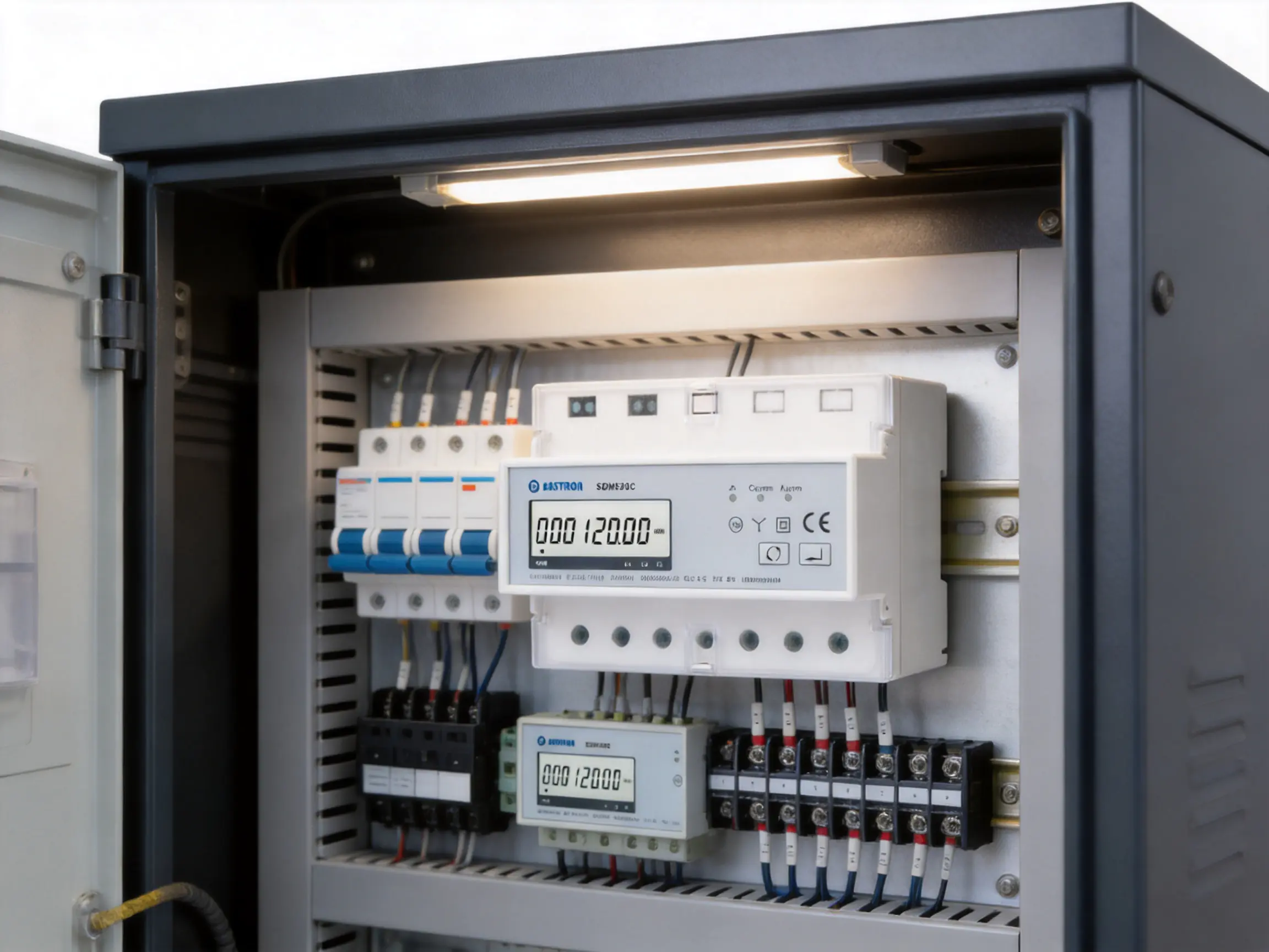
The pulse output provides a straightforward method of transmitting energy accumulation information to an external counter or monitoring system. Pulse-based systems remain useful in applications where a simple electrical output is preferred, where existing equipment already accepts pulses, or where the main controller does not require full two-way Modbus communication.
An energy pulse output can also serve as a secondary data path. For example, a site may use Modbus for detailed operational data while using the pulse output for an independent verification counter. This can support comparison, auditing, and troubleshooting.
A multi-tariff version is available for applications in which energy use must be separated by time period or tariff schedule. Time-based measurement can help facility operators compare peak and off-peak consumption, allocate costs more accurately, and encourage the operation of flexible loads during lower-cost periods.
Multi-tariff capability is useful in commercial buildings, industrial processes, accommodation facilities, and other installations where the cost of energy changes according to time. When combined with remote communication and relay control, it can support automated load scheduling and demand response strategies.
DIN-rail mounting is a practical advantage for modern electrical panels. Standard rail installation allows the meter to be placed alongside circuit protection devices, terminal blocks, communication modules, contactors, and other control equipment. It is particularly suitable for modular distribution boards and compact automation cabinets.
The DIN-rail format helps installers create organized layouts and makes replacement or expansion easier. A meter can be grouped with the circuit it monitors, positioned near communication wiring, or arranged with other measurement devices in a dedicated metering section.
Panel designers should leave sufficient space for conductor bending, terminal access, heat dissipation, inspection, and safe isolation. Communication wiring should be separated from power conductors where practical. Labels should identify the meter address, monitored circuit, relay function, and relevant alarm configuration.
Installation must follow the product documentation and the requirements of local electrical regulations. The meter should be installed by qualified personnel who understand three-phase systems, neutral connections, protective devices, and the hazards associated with energized equipment.
In automatic meter reading systems, the meter provides electrical data to a remote collection platform. Operators can collect energy values from multiple sites or multiple tenant circuits without manually reading each meter. This reduces labor, improves reading frequency, and supports more timely reporting.
Advanced metering infrastructure requires reliable measurement combined with communication and system-level management. The product can function as a field device within a wider network, supplying measurement values, energy totals, event information, and relay status to a central platform.
The built-in relay is valuable in post-pay applications where service activation and disconnection must be performed remotely. A management platform can monitor energy use and operate the supply according to defined administrative or commercial rules.
Commercial buildings often contain many tenants, departments, retail units, or services that require separate energy tracking. The meter can support sub-metering for offices, shops, common areas, HVAC systems, lighting circuits, and equipment rooms.
Industrial users can apply the meter to production lines, workshops, auxiliary systems, machinery groups, and process areas. The measurement of current, power, energy, and power factor can help identify inefficient operation, abnormal loads, and capacity constraints.
Because the meter measures imported and exported energy, it can be useful in systems where power may flow from a local generation source to the grid or from the grid to the facility. It can support monitoring around photovoltaic systems, battery systems, and other distributed energy installations, subject to the requirements of the complete system design.
Construction sites, temporary offices, remote equipment shelters, and managed facilities can benefit from remote monitoring and switching. Reducing the need for physical access is especially valuable where a site is distant, difficult to reach, or operated outside normal working hours.
The product competes effectively with basic energy meters because it offers a wider combination of functions in one compact unit. A simple meter may show accumulated energy, while this device adds multi-parameter measurement, communication, alarms, pulse output, and relay control.
Compared with a separate meter-and-contactor arrangement, the integrated relay can simplify a suitable system by reducing component count and improving the connection between measurement results and switching action. The result may be a cleaner panel, fewer interconnections, and easier centralized control.
Compared with proprietary communication products, Modbus RTU provides broad compatibility. Many automation engineers and system integrators already understand Modbus addressing, register mapping, serial settings, and RS485 network design. This can shorten integration time and reduce dependence on a single software environment.
The Class 0.5s active energy specification is another important advantage. High-accuracy energy data is useful when measurements influence billing allocation, operational decisions, efficiency verification, or customer reporting.
The product also offers flexibility in how data is collected. Users can select RS485 Modbus communication for detailed two-way monitoring and control, pulse output for straightforward energy transmission, or both in systems that require redundancy or multiple data users.
| Product Capability | Practical Benefit |
|---|---|
| Multifunction measurement | Provides broader visibility than an energy-only meter |
| Class 0.5s active energy accuracy | Supports dependable energy analysis and allocation |
| Built-in relay | Enables remote switching without a separate control module in suitable applications |
| 26 alarm values | Supports configurable abnormal-condition monitoring |
| RS485 Modbus RTU | Facilitates integration with common industrial and building systems |
| Pulse output | Connects with pulse counters and legacy monitoring systems |
| DIN-rail format | Fits compact distribution boards and control cabinets |
| Multi-tariff option | Supports time-based energy accounting and load strategies |
The manufacturer behind the product is an established developer and producer of electricity meters, power analyzers, current sensors, communication modules, and energy management systems. Its product development focus covers both measurement hardware and the software, embedded technology, and communication functions required in modern electrical monitoring.
A strong manufacturing organization must control more than final assembly. It must manage design verification, component selection, circuit-board production, firmware development, calibration, environmental testing, communication testing, and final inspection. Energy meters are precision products, so stable manufacturing processes are essential to maintain measurement consistency from one unit to the next.
The company operates a professional laboratory capable of performing electromagnetic compatibility, low-voltage directive, accuracy, and environmental tests according to relevant IEC, EN, GB, and UL requirements. These capabilities support internal verification during product development and production quality control.
Laboratory testing is particularly important for meters used in industrial and commercial environments. The product must continue to operate correctly while exposed to electrical noise, voltage variation, temperature changes, vibration, and other conditions found in real installations. Accuracy testing confirms measurement performance, while EMC testing helps verify that the device neither creates unacceptable interference nor becomes excessively vulnerable to interference from nearby equipment.
The manufacturer follows an ISO 9001 quality management system. A structured quality system helps organize design control, supplier evaluation, manufacturing procedures, inspection records, corrective action, and customer feedback. These processes provide a foundation for consistent production and continuous improvement.
The company has also developed patented technologies in software, embedded software, and hardware. This combination is valuable because a modern energy meter depends on coordinated operation between sensing circuits, microprocessors, firmware algorithms, communication functions, display or configuration systems, and relay control.
Recognition as a high-tech enterprise and high-tech research and development center in electricity application reflects an emphasis on technical development. Cooperation with universities and research institutions can further support the development of new measurement methods, communication functions, and energy management applications.
Energy measurement products must evolve with changing customer expectations. Users increasingly request remote configuration, cloud connectivity, advanced alarms, renewable energy integration, data security, and smaller installation formats. Continuous research and development allows a manufacturer to improve existing products while creating new solutions for emerging requirements.
The company maintains development teams in China and the United Kingdom. International development resources can help combine manufacturing scale with broader engineering perspectives and knowledge of different market requirements. This is useful for a product family serving customers across Europe, Asia-Pacific, the Americas, the Middle East, and Africa.
Testing should cover the complete product lifecycle. During development, engineers verify electrical design, communication behavior, relay operation, alarm response, and measurement accuracy. During production, inspection and calibration help identify assembly or component problems. Before shipment, final testing confirms that each unit meets the required functional criteria.
Environmental testing is important for equipment installed in distribution panels and industrial cabinets. Temperature, humidity, and electrical stress can affect components and measurement behavior. A controlled laboratory provides the means to evaluate these influences before products are placed in service.
The quality of a multifunction meter depends on the interaction of multiple production stages. Component quality is the starting point, but circuit-board assembly, soldering, inspection, firmware loading, calibration, enclosure assembly, and final verification must also be controlled.
During electronic assembly, accurate placement and reliable solder joints are essential. Measurement circuits often use precision components whose characteristics affect accuracy. Automated production equipment can improve repeatability, while inspection systems can help detect placement errors, solder defects, and component abnormalities.
Firmware loading and verification are equally important. The firmware manages measurement calculations, register mapping, communication behavior, alarm logic, pulse generation, and relay control. A controlled programming process helps ensure that the correct firmware version is loaded and that configuration data is properly recorded.
Calibration is a key manufacturing step for precision meters. Each unit should be checked against known electrical reference conditions so that current, voltage, power, frequency, energy, and power factor measurements meet the required specifications. Traceable test equipment and documented procedures help maintain confidence in the results.
Relay testing should verify both command operation and status feedback. The product must correctly interpret remote commands, respond to configured alarm conditions, and return reliable status information to the host system. Pulse output and RS485 communication should also be tested during final inspection.
Enclosure assembly and labeling contribute to installation safety and product usability. Terminals, communication markings, rating information, and product identification should remain clear throughout the service life. Mechanical fit and DIN-rail engagement should be checked to support secure installation in the panel.
A successful installation begins with a clear definition of what the system must measure and control. Engineers should identify the monitored circuits, expected current range, voltage arrangement, communication architecture, alarm requirements, relay duty, tariff structure, and data retention needs.
For Modbus systems, the network plan should assign a unique address to every meter. Communication parameters must match the master device. The wiring topology should avoid unnecessary branches, and termination should be applied in accordance with RS485 best practice.
The host system should document the register map and scaling factors used for each measurement. Energy values, power values, voltage, current, frequency, and power factor may use different units or decimal representations. Correct interpretation is essential for accurate reports and control decisions.
Alarm settings should be reviewed during commissioning. Normal operating values should be recorded first, then warning and trip thresholds should be selected based on the equipment and the application. The system should be tested under controlled conditions so that operators understand the sequence from measurement to alarm to relay action.
Cybersecurity should also be considered when the meter is connected to a wider network. Access to relay control and configuration functions should be restricted to authorized users. Network segmentation, secure supervisory software, password management, event logging, and controlled remote access can reduce operational risk.
One benefit of remote communication is that many operating conditions can be checked without opening the panel. Operators can review energy totals, phase currents, voltage levels, frequency, power factor, alarm events, and relay status through the supervisory platform.
Periodic inspection remains important. Maintenance personnel should check terminal tightness, signs of overheating, cable condition, enclosure cleanliness, communication stability, and relay behavior according to the site maintenance plan. Any inspection must follow appropriate isolation and electrical safety procedures.
Unexpected changes in current or power may indicate equipment deterioration, process changes, or wiring problems. A gradual rise in reactive energy or decline in power factor may indicate changes in motor loading or capacitor equipment. Repeated voltage alarms may indicate a supply issue or an installation problem.
Energy data should be backed up and reviewed over time. Historical trends can reveal seasonal patterns, production changes, equipment degradation, or the results of efficiency measures. The value of the meter increases when its data is converted into practical maintenance and operational decisions.
When selecting this type of meter, users should confirm that the electrical system is a three-phase, four-wire arrangement and that the voltage and current fall within the product’s specified limits. The expected load profile should include normal current, start-up current, continuous current, and possible future expansion.
The communication requirements should also be reviewed. If the installation uses Modbus RTU, the system designer should confirm baud rate, parity, address allocation, cable distance, gateway requirements, and software compatibility. If pulse collection is required, the receiving device must support the relevant pulse interface and energy scaling.
Relay requirements deserve particular attention. The designer should determine whether the relay can switch the intended load directly or whether an external contactor is required. The control philosophy should specify whether phases are switched together or separately and how the system behaves after an alarm or communication failure.
Finally, users should consider the manufacturer’s technical support, laboratory capability, quality system, international experience, documentation, and ability to provide related products. A meter is one part of a larger energy measurement solution, and long-term value depends on the supplier’s ability to support integration and future development.
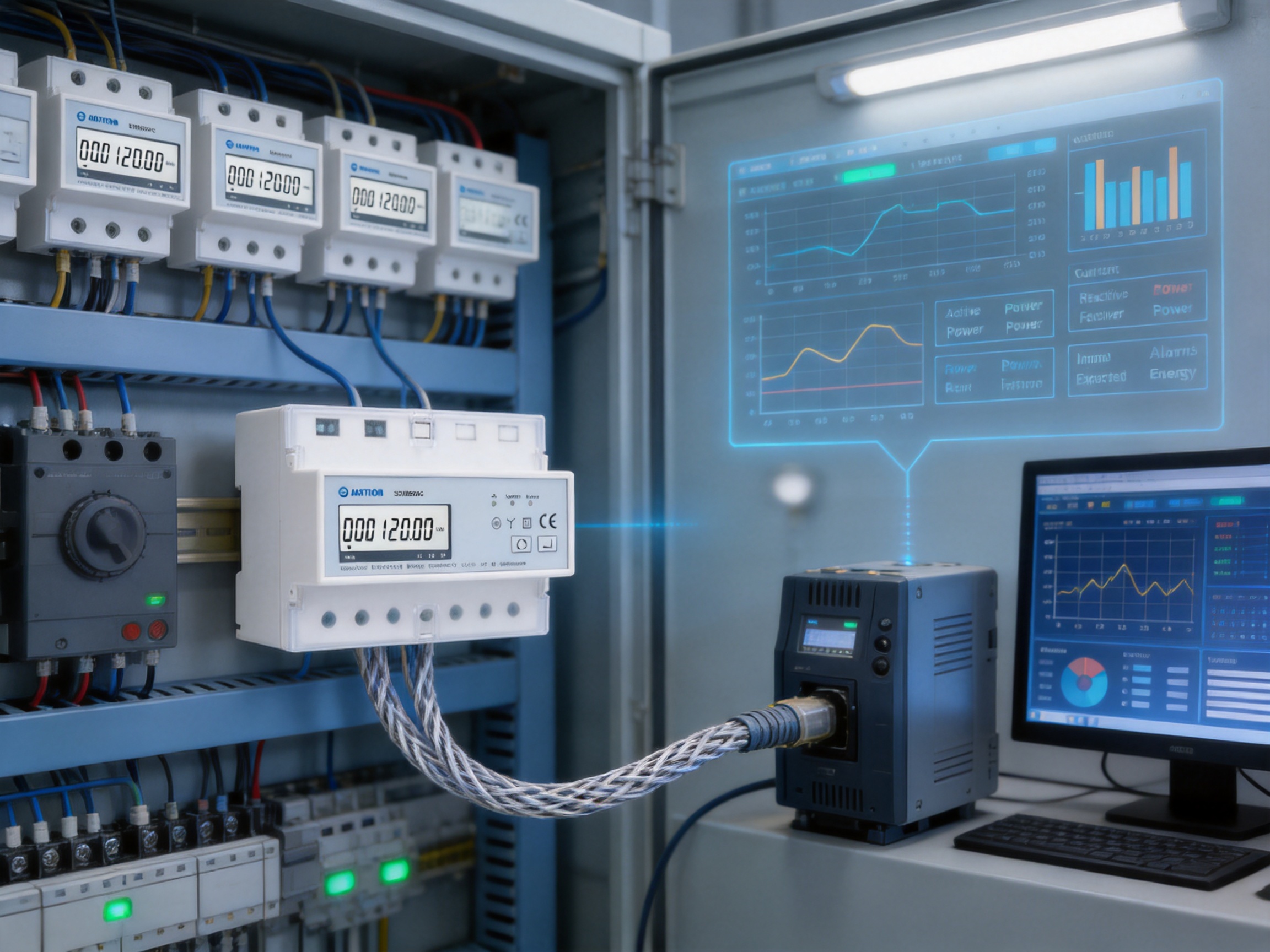
The meter is designed for RMS measurement on a three-phase, four-wire AC system, commonly identified as a 3P4W system.
The specified maximum current is 100 A. The product information also identifies a 5 A rated current, a 0.25 A minimum current, and a 20 mA starting current. The complete installation must be designed within the applicable ratings and local electrical requirements.
Yes. It measures multiple electrical parameters, including current, voltage, power, frequency, power factor, active energy, reactive energy, and import and export energy.
Active energy measurement is specified according to IEC 62053-22 Class 0.5s.
Yes. It includes a built-in relay for remote power control and alarm-related operation. The relay can be controlled through Modbus communication, and each phase can be controlled together or separately according to the application.
The relay can open automatically in response to configured alarm conditions, such as over-current or voltage-related events. The exact behavior should be confirmed during system configuration and commissioning.
The product supports 26 alarm values, allowing users to configure multiple monitoring thresholds for abnormal operating conditions.
The meter uses RS485 with Modbus RTU communication. It supports communication addresses from 1 to 247, baud rates from 1,200 bps to 9,600 bps, selectable parity, and one or two stop bits.
The specified maximum transmission distance is 1,000 meters under suitable RS485 installation conditions. Actual performance depends on cable quality, network design, electromagnetic interference, baud rate, termination, and the number of connected devices.
Yes. The product provides an energy pulse output for connection to pulse counters, data loggers, and compatible monitoring equipment.
Yes. A multi-tariff version is available for applications that need energy information separated by time period or tariff schedule.
The DIN-rail format makes it suitable for distribution boards, control cabinets, sub-metering panels, building management systems, industrial installations, post-pay systems, and remote energy monitoring projects.
Its import and export energy measurement can be useful in systems where energy flows in both directions, including suitable distributed generation applications. The complete installation must be designed and verified by qualified professionals.
Modbus RTU is widely used in industrial and building automation. It allows a host system to read measurement data, monitor alarms, check relay status, and perform supported remote settings or control functions using a common communication method.
The manufacturer develops and produces electricity meters, power analyzers, current sensors, communication modules, and energy management systems. It operates a professional laboratory for EMC, low-voltage, accuracy, and environmental testing and follows an ISO 9001 quality management system.
Yes. Three-phase metering and remote switching involve electrical hazards. Installation, commissioning, protection selection, and relay application should be performed by qualified personnel in accordance with the product documentation and local regulations.
The three-phase DIN-rail multifunction energy meter provides a comprehensive solution for applications that require accurate measurement, remote communication, alarm management, and power control. Its 3P4W design, 100 A maximum current capability, Class 0.5s active energy accuracy, reactive energy measurement, pulse output, and RS485 Modbus RTU interface make it suitable for a wide range of modern electrical systems.
The built-in relay is a major practical advantage. It allows the product to participate in remote service, post-pay operation, load management, and automatic response to abnormal conditions without necessarily requiring a separate switching module. The availability of 26 alarm values further supports preventive monitoring and automated control.
Its DIN-rail format simplifies integration into compact panels, while the combination of Modbus and pulse output supports both advanced automation systems and simpler data collection arrangements. The optional multi-tariff capability adds flexibility for time-based energy management.
Behind the product is a manufacturer with experience in energy measurement, communication technology, laboratory testing, research and development, and international supply. Its ISO 9001 quality management system, professional testing laboratory, patented technologies, and development resources support the consistent production of advanced electricity measurement equipment.
For facilities seeking more than basic energy accumulation, this meter offers a balanced combination of accuracy, connectivity, control, and installation convenience. Properly selected, installed, configured, and maintained, it can provide the measurement foundation required for efficient operation, remote management, improved electrical visibility, and more responsive energy control.
IEC 62053-22, Electricity Metering Equipment — Particular Requirements — Static Meters for Active Energy.
IEC 62053-23, Electricity Metering Equipment — Particular Requirements — Static Meters for Reactive Energy.
ISO 9001, Quality Management Systems — Requirements.
Modbus Organization, Modbus Application Protocol Specification.
RS485 Serial Communication Engineering Practices for Industrial Networks.
Manufacturer product information for the three-phase DIN-rail multifunction energy meter, including electrical characteristics, communication specifications, relay functions, and application data.
Your email address will not be published. Required fields are marked *

We develop and produce high performance electricity meters, power analyzers, current sensors, communication modules and management systems.
Address:NO. 52, Dongjin Road, Nanhu, Jiaxing, Zhejiang, China
Copyright @ Eastron Electronic Co., Ltd. All rights reserved
