

 English
 Español
 Deutsch
 中文简体


Product Consultation
Your email address will not be published. Required fields are marked *
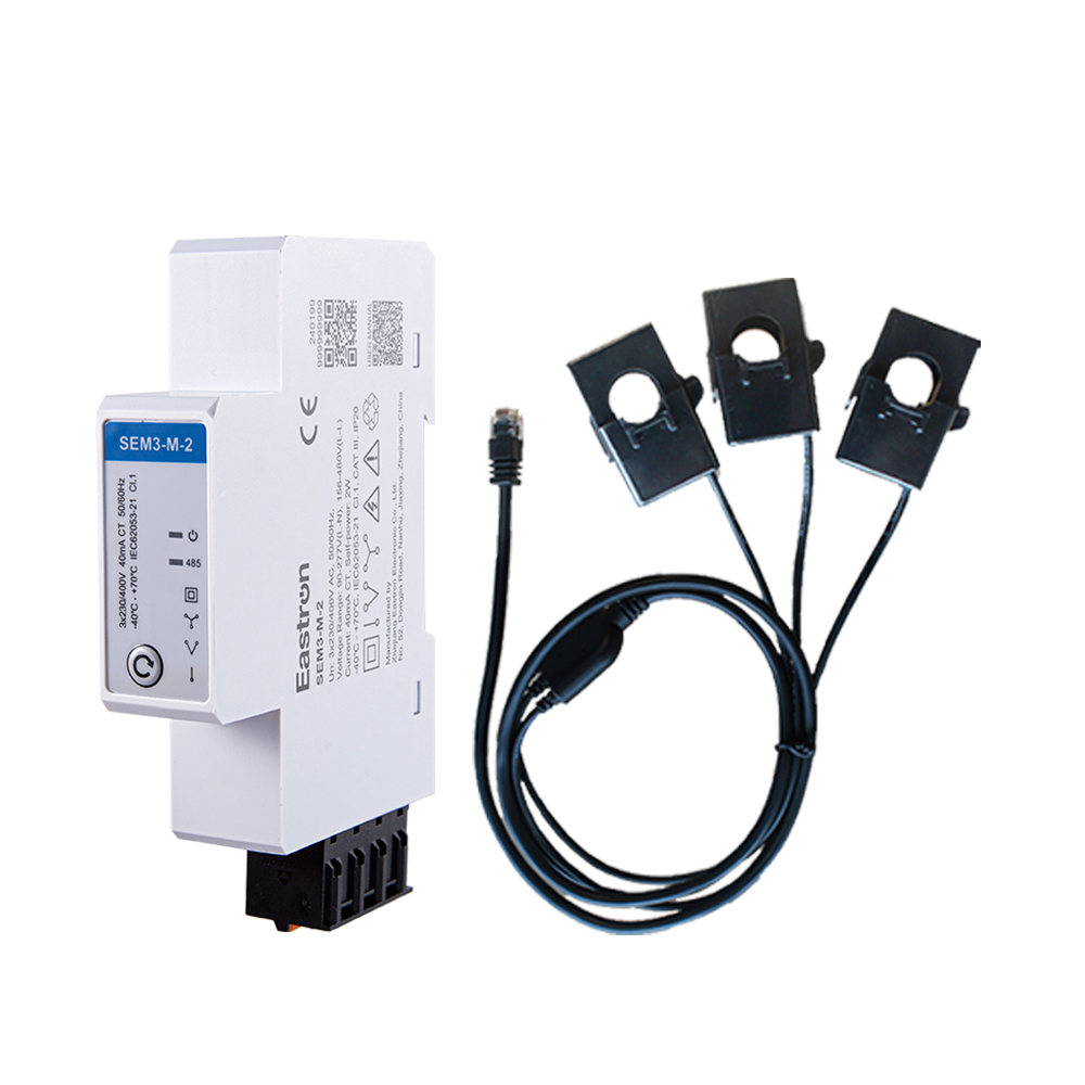
RS485 CT Connection Three Phase Din Rail Energy Meter for PV Metering
May 30,2025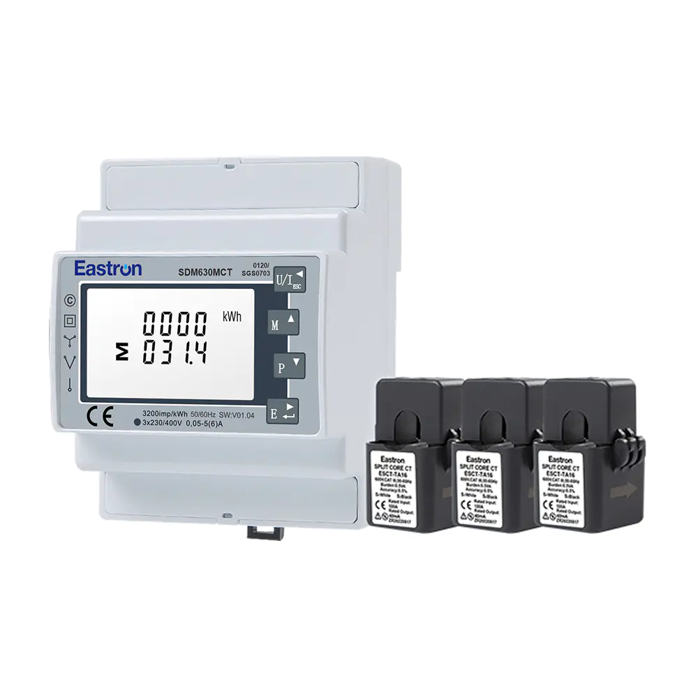
MID/UL CT Type Din Rail Three Phase Multi-function Energy Meter for EV Charging Metering
Nov 24,2022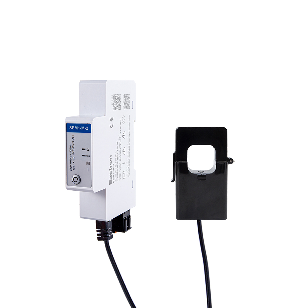
CT Type RS485 Modbus Single Phase Din Rail Energy Meter for PV Metering
May 30,2025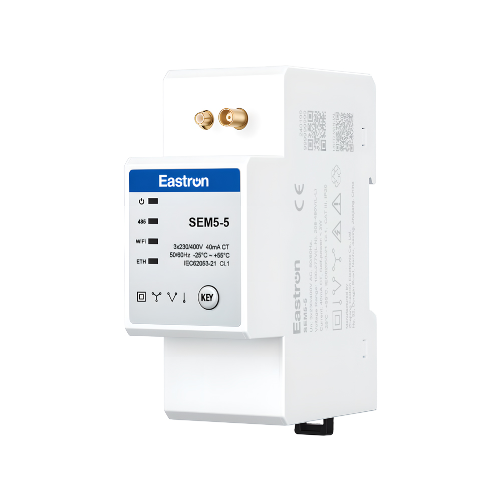
CT Operated Wireless Three Phase Energy Meter for PV Metering
May 30,2025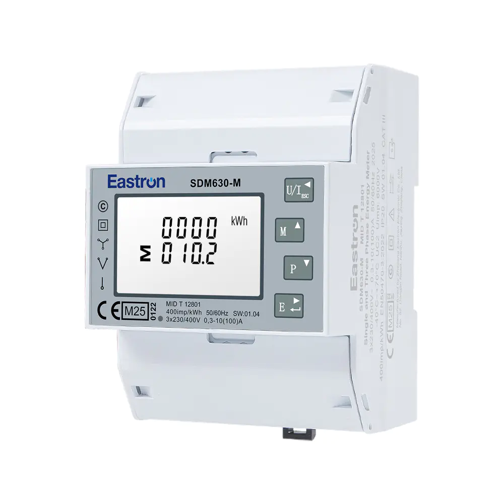
MID UL Certified Din Rail Three Phase Multi-function Energy Meter for EV Charging Metering
Aug 02,2022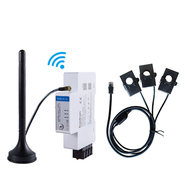
CT Type Three Phase Din Rail Wifi Energy Meter for PV Metering
May 30,2025Content

Modern electrical installations require more than a simple record of total energy consumption. Commercial buildings, industrial facilities, data centers, renewable-energy systems, charging infrastructure, and distributed electrical panels increasingly need accurate measurements of voltage, current, active power, reactive power, apparent power, power factor, frequency, demand, and energy in both directions. They also need a practical way to transmit this information to a supervisory platform, building-management system, energy-management platform, or industrial control network.
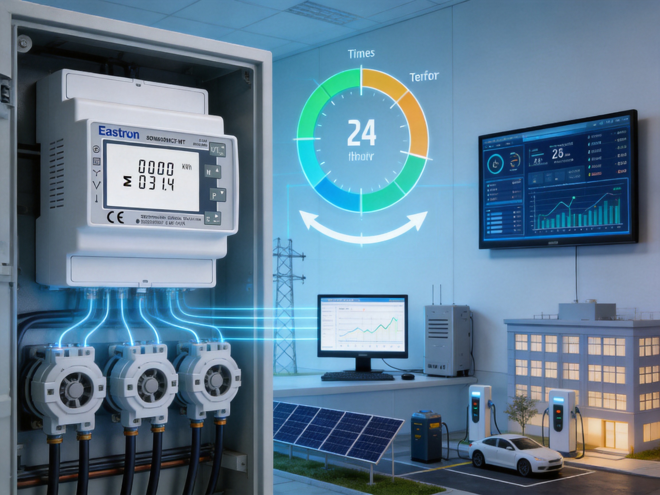
The SDM630MCT-MT is designed for these requirements. It is a multi-function, multi-tariff, CT-operated, three-phase energy meter intended for DIN-rail installation. Its flexible electrical configuration supports 1P2W, 1P3W, 3P3W, and 3P4W systems, while its 1 A or 5 A current-transformer input makes it suitable for higher-current installations where direct connection to the load is impractical. The meter combines local measurement, bidirectional energy recording, pulse outputs, and RS485 Modbus communication in a compact four-module housing measuring 72 mm in width.
The product has been assessed and certified as meeting the requirements of UL 61010. This makes it particularly relevant to projects that require a recognized safety framework for electrical measurement equipment. Its active-energy performance is specified as Class 0.5S according to IEC 62053-22, and its reactive-energy performance is specified as Class 2 according to IEC 62053-23. Together, these features give system designers a flexible instrument for energy monitoring, tenant billing support, tariff analysis, load management, and electrical-performance evaluation.
Energy consumption is rarely constant throughout the day. Loads change according to production schedules, occupancy, weather, equipment cycles, charging behavior, and utility pricing. A facility that only records a monthly total cannot easily identify when energy was used, which operating periods were most expensive, or whether a corrective action produced a measurable improvement.
A modern meter therefore needs to support several layers of information. First, it must measure fundamental electrical quantities accurately. Second, it should distinguish imported and exported energy where power can flow in both directions. Third, it should communicate the data in a form that can be integrated into automation and analytics systems. Finally, it should be economical to install in the limited space available inside distribution boards and control cabinets.
The SDM630MCT-MT addresses these requirements through a combination of CT-operated measurement, multi-parameter monitoring, multi-tariff recording, and digital communication. Rather than functioning only as a kilowatt-hour counter, it operates as a compact electrical measurement node. This allows a single device to provide information that might otherwise require several separate instruments.
For facility operators, the advantage is improved visibility. For panel builders, the advantage is simplified integration. For energy-management engineers, the advantage is access to structured data through RS485 Modbus. For system owners, the advantage is the ability to analyze consumption by time period and electrical direction without replacing the whole distribution architecture.
The meter is designed for three-phase systems and can work with several wiring arrangements: 1P2W, 1P3W, 3P3W, and 3P4W. This flexibility allows the same product family to be applied across different types of electrical networks. It can be used in systems with or without a neutral conductor, provided that the selected wiring configuration and voltage range are suitable for the installation.
The current circuit is CT-operated. The device accepts a 1 A or 5 A CT secondary input, while the programmable CT primary range extends from 1 A to 9999 A. This allows the meter to monitor large feeders and branch circuits without routing the full load current through the meter terminals. The minimum current is specified as 0.05 A, and the starting current is 5 mA.
The voltage input is based on a rated three-phase voltage of 3 x 230/400 V AC. The stated voltage ranges are 100–277 V AC line-to-neutral and 173–480 V AC line-to-line. An auxiliary power supply is required to operate the meter. Depending on the system design, the auxiliary supply may be AC or DC, as specified for the applicable version and installation.
The standard SDM630MCT-MT output arrangement includes two pulse outputs and an RS485 Modbus interface. Pulse outputs are useful for connection to pulse counters, basic building-management inputs, or dedicated energy data loggers. RS485 Modbus provides a more extensive channel for accessing measurements, configuration values, tariff settings, and other supported information.
The product family also includes related communication and power-supply variants. These include versions with dual power source capability, M-Bus EN13757 communication, and LoRaWAN communication. The SDM630MCT-MT described in this article is the multi-tariff RS485 Modbus version, while the broader family allows system integrators to select a communication method that matches the project architecture.
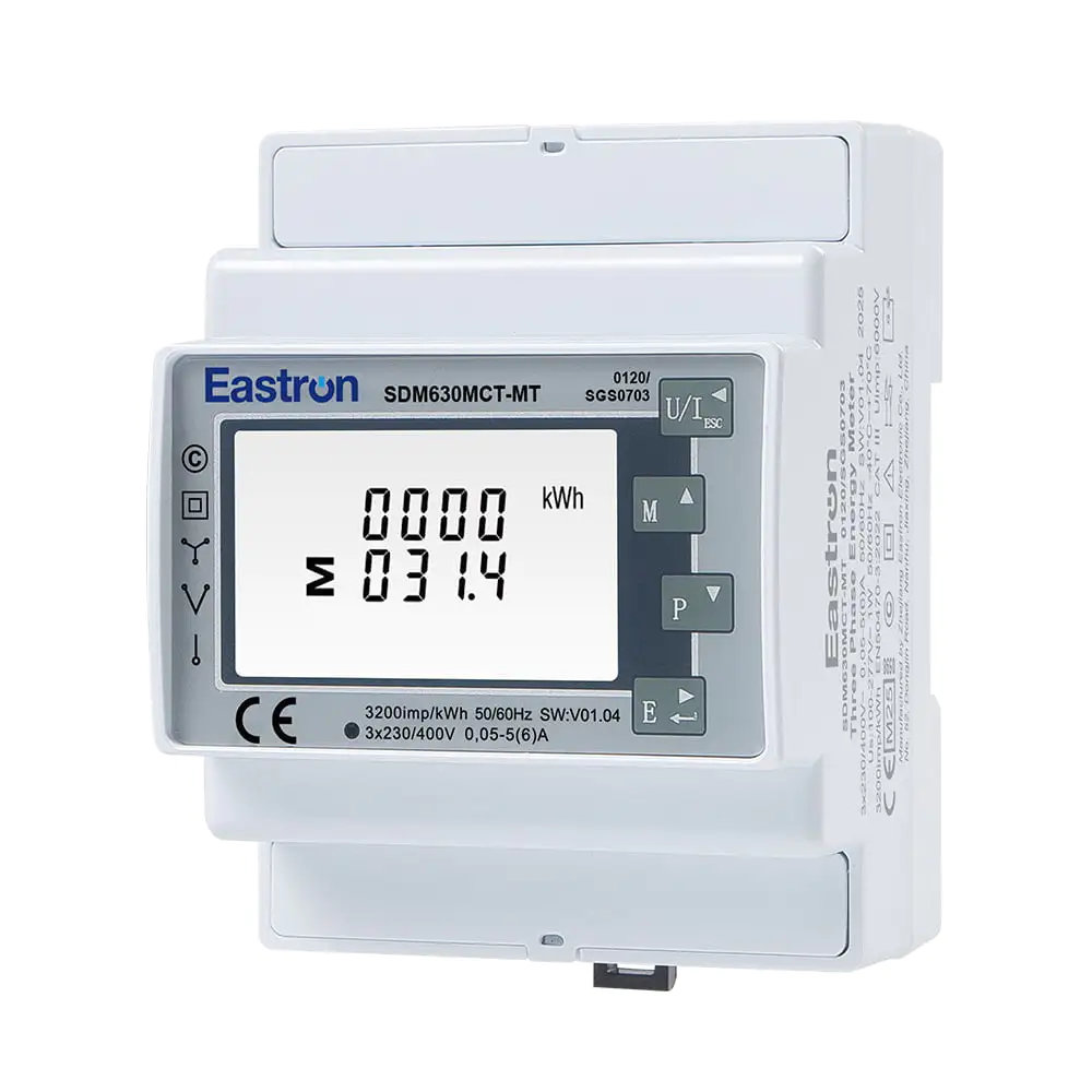
Multi-tariff CT Operated RS485 Din Rail Three Phase UL Energy Meter
One of the defining functions of the SDM630MCT-MT is its multi-tariff capability. The meter supports up to four tariffs and ten time segments. Tariff periods and time segments can be configured through RS485 communication. This allows the meter to record energy according to different periods rather than treating all consumption as a single undifferentiated total.
Time-based measurement is valuable wherever energy prices, operating costs, or internal cost allocations vary during the day. A facility may have peak, shoulder, and off-peak periods. A property manager may need to distinguish daytime and nighttime consumption. A manufacturing plant may want to compare scheduled production periods with standby periods. A charging installation may need to understand consumption during high-demand and low-demand windows.
Multi-tariff operation also supports more informed operational decisions. If a facility discovers that a large proportion of its energy is consumed during an expensive period, managers can evaluate whether production can be rescheduled, storage can be used, or nonessential loads can be shifted. The meter does not make these decisions automatically, but it provides the structured measurement needed to support them.
The ability to configure tariffs through communication is particularly useful in installations where the meter is located inside a sealed or restricted-access panel. Authorized personnel can adjust the schedule through the supervisory system instead of manually accessing every meter. This can reduce service time and help maintain a consistent configuration across a group of devices.
Multi-tariff functionality is also useful for internal cost allocation. In a multi-tenant building, an industrial campus, or a facility with separate departments, energy data can be assigned according to time and electrical area. When combined with appropriate contractual arrangements and verification procedures, the readings can support operational accounting and energy-performance reporting.
A major advantage of CT-operated metering is the ability to measure high-current circuits without placing the full current directly through the meter. Current transformers are selected according to the expected primary current, and their secondary output is connected to the meter. The programmable CT primary setting enables the device to calculate and display primary-side values based on the installed transformer ratio.
This architecture is suitable for main incomers, subdistribution feeders, motor-control centers, generator outputs, photovoltaic combiner systems, battery systems, and other circuits where current may exceed the practical direct-input rating of a compact DIN-rail meter. It also provides flexibility when the panel design requires the measurement device to be located away from the main conductor.
Correct CT selection and installation remain essential. The CT primary rating should be appropriate for the expected current, the secondary rating must match the meter input setting, and the polarity and phase association must be maintained. The CT secondary circuit should be wired and handled according to applicable safety procedures. A measurement system can only achieve its expected performance when the transformer ratio, wiring, phase sequence, and configuration are correct.
The meter supports 1 A and 5 A CT secondary inputs, covering common instrumentation-transformer standards. The broad programmable primary range from 1 A to 9999 A helps reduce the need for multiple product models across a project. Panel builders can therefore standardize the meter platform while selecting CTs that match different feeder sizes.
Compared with a direct-connected meter, a CT-operated design can also simplify retrofit work. Existing conductors may not need to be disconnected and routed through a new meter. In many cases, suitable CTs can be installed around existing conductors while the measurement unit is mounted on the DIN rail. All retrofit work must be performed by qualified personnel under the applicable isolation and electrical-safety procedures, but the architecture can reduce mechanical disruption to the distribution system.
The SDM630MCT-MT provides multi-measurement capability for a wide range of electrical values. Supported measurements include active energy, reactive energy, active power, reactive power, apparent power, power factor, frequency, voltage, current, and demand-related information. This broad measurement range helps users move from simple consumption tracking to a more complete assessment of electrical performance.
Voltage readings can help identify supply imbalance, abnormal operating conditions, or voltage levels outside the expected range. Current measurements can reveal uneven phase loading, overloaded feeders, and changing operating patterns. Active power indicates the rate at which useful electrical work is being consumed, while reactive power can reveal the behavior of inductive and capacitive loads.
Apparent power is important for understanding the total loading imposed on conductors, transformers, and switchgear. A facility may have a moderate active-power reading but still place a substantial apparent-power demand on the electrical infrastructure if the power factor is low. Monitoring both values supports more effective capacity planning and power-factor-improvement decisions.
Power factor provides an indication of how effectively current is being converted into useful active power. A declining power factor may be associated with motors operating at light load, poorly compensated reactive loads, or changes in equipment operation. By exposing these conditions, the meter can contribute to maintenance investigations and energy-efficiency programs.
Frequency monitoring helps verify the stability of the supply and can be useful in systems that include generators, inverters, or other distributed energy resources. Demand measurements can support analysis of maximum loading and help operators understand whether a facility is approaching a contractual or equipment capacity limit.
The measurement method is specified as RMS including harmonics on a three-phase AC system. This is significant because practical electrical waveforms are not always perfect sine waves. Variable-speed drives, switching power supplies, LED drivers, inverters, computers, and other electronic loads can introduce waveform distortion. A measurement approach that considers RMS values and harmonics provides a more realistic representation of the electrical conditions experienced by the installation.
Measurement accuracy is a central consideration when selecting an energy meter. The published specifications identify voltage accuracy of ±0.5%, current accuracy of ±0.5%, frequency accuracy of ±0.2%, and power-factor accuracy of ±1%. Active, reactive, and apparent power are each specified at ±1%.
For active energy, the meter is specified as Class 0.5S according to IEC 62053-22. This performance level is appropriate for many monitoring, energy-management, and submetering applications where reliable energy data is needed across a broad operating range. Reactive energy is specified as Class 2 according to IEC 62053-23.
Accuracy should always be considered together with installation conditions. The overall performance of a CT-operated system depends on the meter, the CT accuracy, the CT burden, conductor routing, phase identification, voltage connections, temperature, waveform characteristics, and correct configuration. The meter’s stated class is therefore an important part of the system specification, but it does not remove the need for correct engineering and commissioning.
Compared with basic low-cost energy counters, a meter with documented measurement classes and multiple electrical-value specifications offers a stronger basis for professional energy-management work. Users can compare readings over time, investigate unusual values, and establish repeatable measurement procedures. The combination of accuracy information and digital communication is especially useful for installations that need traceable, structured data rather than occasional visual readings.
Electrical energy does not always flow in one direction. A site may import energy from the utility and export energy from solar generation, a battery inverter, a generator, or another distributed resource. Electric-vehicle charging sites may also experience changing power-flow conditions as equipment is added or upgraded. The SDM630MCT-MT supports bidirectional measurement, making it suitable for applications in which imported and exported energy both matter.
Bidirectional measurement helps operators distinguish consumption from generation. This is essential for evaluating renewable-energy self-consumption, analyzing battery charge and discharge behavior, monitoring microgrids, and understanding the net effect of on-site generation. It can also help identify reverse-current conditions caused by incorrect CT polarity or phase wiring during commissioning.
In a solar installation, for example, the meter may be installed at the point of common coupling or on a selected feeder. During periods of low generation, the site imports energy. During periods of high generation and low local demand, the site may export energy. Recording both directions provides a more complete picture than a meter that only accumulates forward energy.
Bidirectional data can also support control strategies. An energy-management system may use import and export readings to limit grid demand, coordinate battery operation, or adjust flexible loads. Since the meter provides RS485 communication, these values can be incorporated into a larger control or monitoring system when the relevant software and controls are properly engineered.
The integrated RS485 Modbus interface is one of the product’s most important advantages for connected electrical systems. RS485 is widely used in industrial and building-control environments because it supports reliable serial communication over distances that are practical for many panels and facilities. The meter specifies a maximum transmission distance of 1000 m, subject to suitable cabling, topology, grounding, termination, and electromagnetic conditions.
The communication address range is 1–247. Transmission speeds from 2400 bps to 38400 bps are supported. Parity may be set to none, odd, or even, with none identified as the default. One or two stop bits are available, and the response time is specified as less than 100 ms. These settings allow the meter to be adapted to common Modbus RTU network requirements.
Through Modbus communication, a supervisory system can obtain electrical measurements without relying on manual readings from the front of the device. Depending on the implemented register map and software configuration, a system may collect voltage, current, power, energy, power factor, frequency, demand, tariff information, and status values. It may also use communication to configure CT ratios, addresses, tariff schedules, and other supported parameters.
Digital communication improves scalability. A single monitoring platform can collect data from multiple meters distributed across a building or industrial site. Operators can compare feeders, departments, production lines, floors, or tenants from one interface. This makes it easier to establish energy baselines, identify unusual consumption, and track improvements after equipment changes.
RS485 communication also supports integration with gateways and protocol-conversion equipment. A Modbus network can be connected to a supervisory computer, programmable logic controller, building-management system, industrial gateway, or cloud-connected data concentrator. The exact integration method depends on the project, but the standard interface reduces the need for proprietary communication hardware.
Network engineering remains important. RS485 networks should use suitable twisted-pair communication cable, follow the recommended bus topology, avoid excessive star connections, and apply termination and biasing practices appropriate to the installation. Shielding and grounding should be considered in environments with significant electrical noise. Device addresses must be unique, and the baud rate, parity, and stop-bit settings must match the host system.
In addition to RS485, the meter provides two pulse outputs. Pulse outputs are useful when a receiving device only needs accumulated energy pulses rather than a complete collection of electrical measurements. They can be connected to pulse counters, programmable controllers, alarm or automation inputs, or legacy energy-monitoring equipment that accepts standardized pulses.
The coexistence of pulse outputs and Modbus communication gives system designers more than one integration option. A small installation may use pulse outputs for a simple data logger, while a larger installation may use Modbus for detailed data collection. Pulse channels can also provide a secondary data path or a convenient connection to a dedicated monitoring function.
When pulse outputs are used, the receiving equipment must be compatible with the electrical characteristics, pulse value, and configuration of the meter. Cable routing and input isolation should be considered, especially when the pulse signal travels between separate panels or buildings. Installation and commissioning should verify that the receiving system counts pulses correctly and that the accumulated total corresponds to the meter display or communication value.
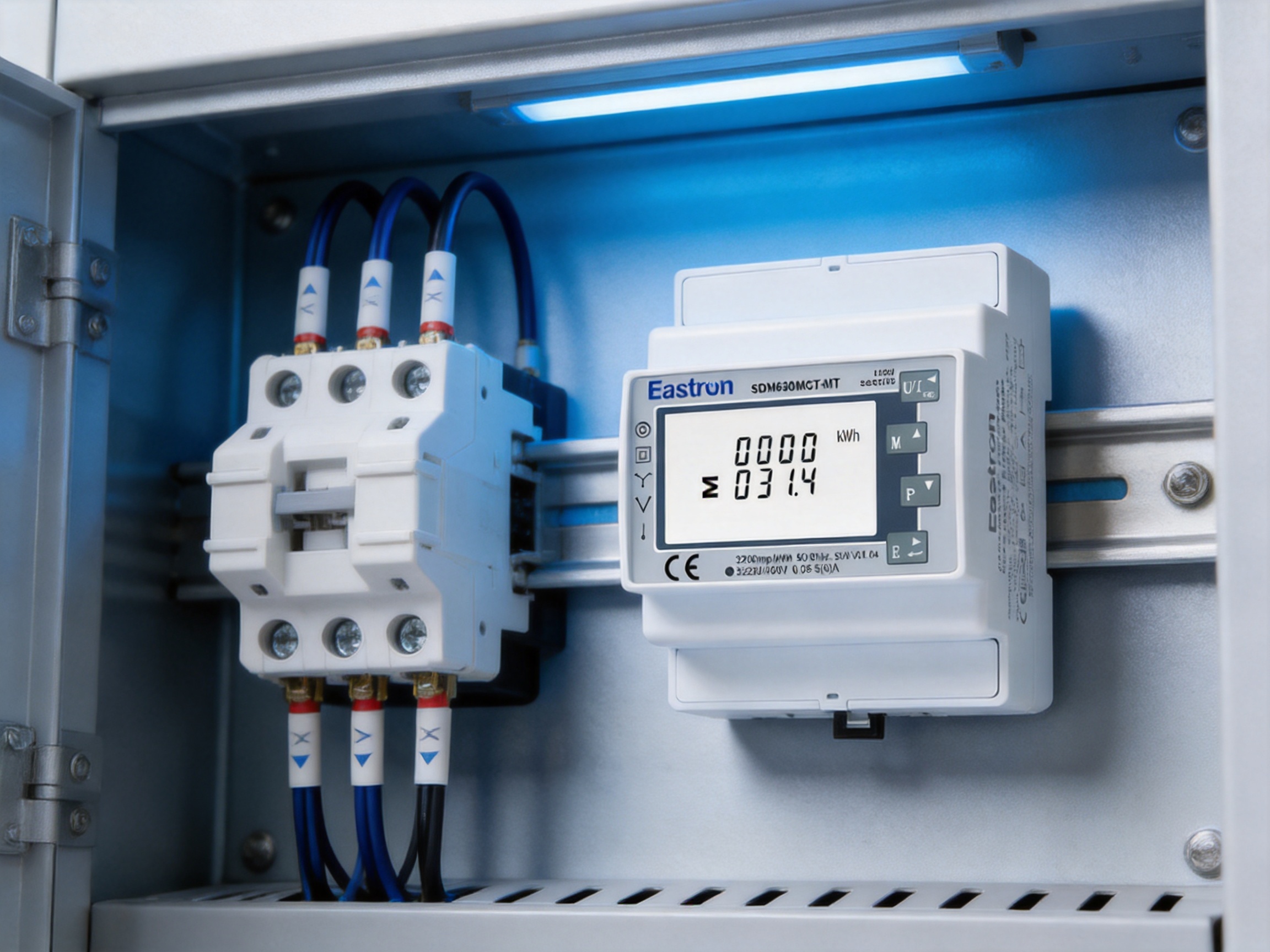
Panel space is expensive and often limited. The meter is designed as a four-module DIN-rail device with a width of 72 mm. This compact form factor allows it to be mounted alongside circuit protection, contactors, terminal blocks, communication equipment, and other control components.
A narrow DIN-rail meter can be particularly valuable in retrofit projects. Existing distribution boards may have only a small amount of spare capacity, and a large standalone instrument may require a new enclosure or extensive modification. The 72 mm form factor helps reduce the space required for installation while retaining a display-oriented multifunction measurement platform.
DIN-rail mounting also supports consistent panel construction. Electrical contractors and panel builders can use standard mounting practices and arrange groups of meters in a clear row. This can simplify inspection, labeling, replacement, and future expansion. The final installation must still provide adequate clearance, wiring space, ventilation, and access in accordance with the applicable electrical code and product instructions.
The compact enclosure should not be confused with limited capability. The device combines CT measurement, multi-tariff energy recording, bidirectional measurement, two pulse outputs, and RS485 communication in the same enclosure. This integration can reduce the number of separate components needed for a basic energy-monitoring point.
The meter has been assessed and certified as meeting the requirements of UL 61010. UL 61010 is associated with safety requirements for electrical equipment used for measurement, control, and laboratory applications. For project owners, consultants, and approval teams, a recognized safety assessment can simplify the product-selection process when specifications require UL-related compliance.
Safety certification does not replace correct installation. The meter must be installed by qualified personnel, and the system must include appropriate isolation, overcurrent protection, conductor sizing, CT protection practices, labeling, and enclosure arrangements. The voltage and current limits must not be exceeded, and the wiring configuration must correspond to the selected system type.
UL-oriented product development is also relevant to international panel projects. Contractors may work with different regional standards, inspection expectations, and procurement requirements. A device supported by documented safety and performance information is easier to evaluate during design review. This can reduce uncertainty when a project involves multinational stakeholders or equipment intended for export markets.
The product’s UL certification, IEC energy-class specifications, and communication capabilities create a balanced profile. It can serve projects that prioritize safety recognition, measurement performance, and digital integration at the same time. These characteristics distinguish it from simple meters that may provide only a local display or basic pulse counting.
In commercial buildings, the meter can monitor main feeders, tenant areas, HVAC systems, lighting panels, retail spaces, offices, and common facilities. Multi-tariff recording helps facility teams compare energy use across different time periods, while Modbus communication allows data to be brought into a building-management or energy-management platform.
Because the meter can measure voltage, current, power, power factor, and energy, it can support both cost analysis and electrical maintenance. A facility manager may use energy data to identify after-hours loads, compare floors, investigate abnormal power factor, or evaluate the effect of lighting and HVAC upgrades.
Industrial plants often have a combination of large motors, variable-speed drives, heating equipment, compressors, conveyors, process machinery, and auxiliary systems. CT operation allows measurement of large feeders without routing high current through a compact meter. The measurements can be used to compare production lines, monitor process areas, and evaluate demand patterns.
Demand and power measurements can also help identify equipment that operates inefficiently or remains energized during nonproduction periods. Reactive and apparent-power data may be useful when reviewing transformer loading, capacitor-bank performance, and the impact of large motor loads.
Solar photovoltaic systems, battery systems, and generator installations require an understanding of power flow in both directions. Bidirectional measurement allows operators to distinguish imported grid energy from exported energy and to observe how local generation affects the site’s net demand.
The meter can be used at selected distribution points, provided that its voltage, current-transformer, and auxiliary-power requirements are suitable for the application. Modbus communication can make the measurements available to a local energy-management controller or gateway.
Charging sites often experience changing loads, scheduled charging periods, and demand-management requirements. The meter can monitor a feeder or charging group, provide time-based energy information, and communicate electrical values to a supervisory platform. Bidirectional measurement may also be relevant to installations that support vehicle-to-building or vehicle-to-grid functionality, subject to the design of the charging equipment and control system.
Data centers and technical rooms require continuous visibility of electrical loading. Monitoring voltage, current, apparent power, power factor, and energy can help operators understand the loading of distribution paths and identify changes in equipment demand. The compact DIN-rail design allows the meter to be installed in auxiliary distribution panels and subdistribution sections where space is constrained.
Submetering allows a facility to move beyond a single utility bill and understand the performance of individual areas or systems. The meter’s CT input, multiple measurement values, time-based tariff capability, and communication interface make it suitable for many submetering projects. Data can be collected over time to establish a baseline and evaluate changes after an energy-efficiency measure is introduced.
The first advantage is functional breadth. A basic energy counter may provide only total kilowatt-hours, while this meter combines active and reactive energy with voltage, current, power, power factor, frequency, demand, and other electrical measurements. This reduces the need to install multiple independent instruments for routine monitoring.
The second advantage is wiring flexibility. Support for 1P2W, 1P3W, 3P3W, and 3P4W systems makes the product adaptable to different network arrangements. A product that can serve several system configurations can reduce engineering complexity and simplify inventory planning.
The third advantage is CT compatibility. The 1 A and 5 A CT secondary inputs and programmable primary range allow the meter to monitor circuits that cannot be served by a small direct-connected meter. This expands the range of applications from small distribution points to large feeders.
The fourth advantage is multi-tariff functionality. Time-segmented data gives users more insight into when energy is consumed. This is more useful for cost optimization and operational planning than a single cumulative reading.
The fifth advantage is bidirectional measurement. This is increasingly important as renewable generation, storage, and flexible energy systems become more common. A meter limited to forward energy cannot provide the same level of information for sites with changing power-flow direction.
The sixth advantage is connectivity. RS485 Modbus is widely understood by automation and energy-management engineers. The meter can therefore be connected to a broader control architecture instead of remaining an isolated display instrument.
The seventh advantage is installation efficiency. A four-module, 72 mm DIN-rail enclosure helps conserve panel space and supports standardized mounting. When a product combines several functions in a compact housing, the overall installation may require fewer components and less wiring.
These advantages do not mean that every project should use the same meter. Final selection should consider the required accuracy, communication method, voltage system, CT arrangement, environmental conditions, certification requirements, and local regulations. However, the product’s combination of functions provides a strong solution for projects seeking a balance between capability, installation practicality, and cost control.
Eastron Electronic Co., Ltd. is headquartered in Jiaxing, China, near Shanghai, Hangzhou, and Jiangsu. The company develops and manufactures electricity meters, power analyzers, current sensors, communication modules, and energy-management products. Its product range reflects a focus on electricity measurement and related digital energy solutions.
The company’s manufacturing strength is supported by in-house technical development in China and the United Kingdom. This international engineering structure allows product development teams to work across hardware, embedded software, measurement technology, communication functions, and application requirements. Cooperation with universities and technical institutions further supports research and the introduction of new technologies.
For a multifunction meter, manufacturing capability is not limited to assembling a plastic enclosure and a circuit board. The product must coordinate voltage sensing, CT current measurement, analog-to-digital conversion, calculation algorithms, display functions, nonvolatile data storage, clock and tariff management, pulse generation, and serial communication. Each of these elements must work together consistently across production batches.
The company has established a professional laboratory capable of performing EMC, LVD, accuracy, and environmental tests according to IEC, EN, GB, and UL standards. These test capabilities are important because an energy meter may be installed in electrically noisy environments and must continue to measure and communicate reliably. Electromagnetic compatibility testing helps evaluate immunity and emissions, while low-voltage and safety testing addresses electrical protection requirements.
Accuracy testing is particularly important for a CT-operated meter. The production and quality process must consider current ratios, phase relationships, voltage channels, power calculations, energy accumulation, and behavior across different operating conditions. Environmental testing helps evaluate product performance under temperature, humidity, and other conditions relevant to field use.
The company also holds patented technologies in software, embedded software, and hardware. Such intellectual-property development indicates that the product platform is supported by proprietary engineering work rather than being limited to generic, off-the-shelf measurement functions. Embedded software is especially important for multi-tariff scheduling, bidirectional energy calculation, communication handling, data management, and user configuration.
ISO 9001 quality-management practices provide a framework for controlled processes, documentation, corrective action, and continuous improvement. The company’s production is also approved by SGS according to MID standards. Although the specific certification requirement for each project must be reviewed separately, these quality and assessment activities demonstrate an organized approach to product reliability and manufacturing control.
Another strength is the breadth of the company’s product portfolio. Eastron supplies meters and energy products for applications that include single-phase and three-phase measurement, direct and CT-operated metering, power analysis, communication gateways, current transformers, and system solutions. This breadth can help customers coordinate several measurement points through related product families rather than combining equipment from unrelated suppliers.
Reliable metering begins at the design stage. The measurement circuit, isolation structure, power supply, communication interface, enclosure, and firmware must be developed as an integrated system. Design verification can identify issues before mass production, while documented production procedures help ensure that approved designs are reproduced consistently.
Incoming-material control is another important part of quality assurance. Electronic components, terminals, housings, displays, communication interfaces, and other parts must meet the relevant specifications. Traceability and inspection help reduce the risk that variations in component quality will affect measurement stability or product life.
During assembly, production controls should address soldering quality, board cleanliness, connector placement, terminal integrity, enclosure assembly, labeling, and firmware programming. A meter used in a distribution panel must also withstand the mechanical and electrical conditions associated with installation and service.
Calibration and final testing are essential for measurement products. The meter should be tested against controlled reference conditions so that voltage, current, power, energy, frequency, and communication functions can be verified. Functional testing can confirm that pulse outputs operate correctly, Modbus communication responds as expected, and tariff settings are stored and applied properly.
Environmental and EMC capabilities are especially valuable for products that may be installed near contactors, motor drives, switching power supplies, generators, and other sources of interference. Testing according to recognized standards helps identify weaknesses and improve the product before it reaches the field.
After-sales technical support is also part of the total product value. Meter installation often involves CT selection, wiring diagrams, communication parameters, register mapping, tariff configuration, and interpretation of measurements. Eastron provides technical and after-sales teams to support customers in different regions, helping users obtain the intended value from the installed equipment.
Before installation, the system voltage, frequency, wiring configuration, CT ratio, auxiliary supply, communication requirements, and environmental conditions should be confirmed. The selected meter version must match the project specification. The wiring diagram and product documentation should be reviewed by qualified personnel before any connection is made.
The phase sequence and CT polarity should be checked carefully. Reversed CT polarity can cause incorrect power direction or unusual power-factor readings. Connecting a CT to the wrong phase can also produce inaccurate phase measurements and misleading total values. Commissioning should include a comparison with a trusted reference or a known operating condition.
The CT primary and secondary settings must correspond to the installed transformer. If a 5 A CT is installed but the meter is configured for a 1 A input, or if the primary ratio is entered incorrectly, the displayed values will not represent the actual circuit. Configuration records should be retained so that maintenance teams can understand the installed settings.
Voltage connections require suitable protective devices and isolation arrangements. The auxiliary supply must be compatible with the meter version. Conductors should be sized and routed according to applicable electrical standards. The enclosure should protect the device from conditions outside its specified operating environment, including excessive moisture, contamination, vibration, and heat.
For RS485 networks, each device should have a unique address. Baud rate, parity, and stop-bit settings must match the host. Communication wiring should be routed to minimize exposure to power cables and high-noise equipment. If long cable runs are used, termination and network topology should be reviewed carefully.
After installation, the commissioning process should verify the display, voltage readings, current readings, power direction, energy accumulation, pulse outputs, and communication response. Where multi-tariff operation is required, the real-time clock, tariff schedule, and time segments should be checked against the project requirements.
Installing a meter is only the first step. The greatest value comes from using the data to support decisions. A facility can begin by establishing a baseline for total energy, peak demand, power factor, and operating-period consumption. Once the baseline is available, unusual changes can be detected more quickly.
Data should be reviewed at an interval appropriate to the application. Monthly totals may be sufficient for a small office, while an industrial process or charging site may require five-minute, one-minute, or event-based analysis through a connected system. The meter provides the measurement point, while the supervisory platform determines how data is stored, visualized, and analyzed.
Tariff data can be compared with operating schedules. If high consumption consistently occurs during the most expensive period, managers can evaluate load shifting. If a facility has high reactive power during low-production periods, the maintenance team can inspect motors, compensation equipment, or control settings. If current is unbalanced between phases, the distribution arrangement can be reviewed.
Bidirectional readings can be compared with renewable generation and battery data. This can reveal whether on-site generation is being used effectively or exported during periods when local loads could have been scheduled. Over time, the measurements can support decisions about storage capacity, charging schedules, demand response, or additional generation.
Energy data can also support maintenance. A gradual increase in current or apparent power may indicate equipment deterioration, process changes, or an unexpected additional load. A sudden loss of power factor may indicate a failed capacitor stage or a change in motor operation. These observations do not replace professional diagnostics, but they can help direct attention to the right area.
| Product type | Multi-function, multi-tariff, CT-operated three-phase energy meter |
| Installation | DIN rail, four modules, 72 mm wide |
| Supported wiring systems | 1P2W, 1P3W, 3P3W, and 3P4W |
| CT secondary input | 1 A or 5 A |
| Programmable CT primary range | 1–9999 A |
| Minimum current | 0.05 A |
| Starting current | 5 mA |
| Rated voltage | 3 x 230/400 V AC |
| Voltage range | 100–277 V AC line-to-neutral; 173–480 V AC line-to-line |
| Measurement method | RMS including harmonics on three-phase AC systems |
| Voltage accuracy | ±0.5% |
| Current accuracy | ±0.5% |
| Frequency accuracy | ±0.2% |
| Power-factor accuracy | ±1% |
| Active, reactive, and apparent power accuracy | ±1% |
| Active-energy performance | Class 0.5S, IEC 62053-22 |
| Reactive-energy performance | Class 2, IEC 62053-23 |
| Outputs | Two pulse outputs and RS485 Modbus |
| Multi-tariff capacity | Up to four tariffs and ten time segments |
| Modbus address range | 1–247 |
| Modbus transmission speed | 2400–38400 bps |
| Maximum stated Modbus transmission distance | 1000 m |
| Modbus parity | None, odd, or even |
| Modbus stop bits | One or two |
| Typical response time | Less than 100 ms |
| Safety assessment | UL 61010 requirements |
It is a CT-operated, three-phase, multi-function energy meter designed for DIN-rail installation. It supports multi-tariff measurement, bidirectional energy recording, two pulse outputs, and RS485 Modbus communication.
Yes. The product supports 1P2W, 1P3W, 3P3W, and 3P4W configurations. The wiring arrangement must be selected and connected correctly according to the installation design and product instructions.
The meter supports 1 A and 5 A CT secondary inputs. The CT primary setting can be configured across a range from 1 A to 9999 A.
No. It measures a broad range of electrical quantities, including active energy, reactive energy, active power, reactive power, apparent power, voltage, current, power factor, frequency, and demand-related values.
Bidirectional measurement records energy flow in both directions. This is useful for solar installations, battery systems, generators, microgrids, and other applications in which a site may import and export energy.
The meter supports up to four tariffs and ten time segments. Tariffs and time segments can be configured through RS485 communication.
The SDM630MCT-MT uses RS485 Modbus communication. The interface supports addresses from 1 to 247 and transmission speeds from 2400 bps to 38400 bps.
Yes. Its RS485 Modbus interface can be connected to suitable building-management systems, energy-management platforms, programmable controllers, gateways, and data-acquisition equipment. The host system must be configured according to the meter’s communication settings and register documentation.
The two pulse outputs can provide energy pulses to compatible counters, data loggers, controllers, or monitoring equipment. They are useful when a receiving system does not require the full range of Modbus data.
Yes. The meter requires an auxiliary power supply to operate. The supply type and rating must match the selected version and the product documentation.
It is suitable for many high-current applications because it uses external current transformers rather than requiring the full load current to pass directly through the meter. The CT primary rating and secondary output must be selected correctly for the circuit.
The product has been assessed and certified as meeting the requirements of UL 61010. Installation must still follow applicable electrical codes, safety procedures, and product instructions.
Commissioning should verify the wiring configuration, phase sequence, CT ratio, CT polarity, voltage readings, current readings, power direction, energy accumulation, pulse outputs, communication settings, and tariff schedule. Readings should be compared with expected operating conditions or a suitable reference.
The meter can support submetering and energy-cost analysis, but the suitability for legal billing or revenue metering depends on the applicable jurisdiction, contract, certification, installation method, and project requirements. These conditions should be confirmed with the responsible authority or project engineer.
The SDM630MCT-MT combines the functions required by modern electrical-monitoring systems in a compact DIN-rail format. Its CT-operated architecture supports large feeders and retrofit applications, while its compatibility with 1P2W, 1P3W, 3P3W, and 3P4W systems provides design flexibility. Its measurement range extends beyond basic energy counting to include voltage, current, power, power factor, frequency, demand, and bidirectional energy.
Multi-tariff operation gives users a practical way to analyze consumption across different time periods. Two pulse outputs support simple data collection, while RS485 Modbus enables integration with energy-management systems, building controls, industrial automation, and data gateways. The four-module, 72 mm DIN-rail housing helps conserve panel space without sacrificing multifunction capability.
The product’s Class 0.5S active-energy specification, Class 2 reactive-energy specification, RMS measurement approach, and UL 61010 assessment provide a strong technical foundation for professional applications. Its value is further supported by Eastron’s focus on electricity measurement, international engineering resources, laboratory testing, ISO 9001 quality practices, patented technologies, and broad product portfolio.
For commercial buildings, industrial plants, renewable-energy installations, charging infrastructure, data centers, and submetering projects, the meter offers a practical combination of measurement depth, communication capability, tariff flexibility, and installation efficiency. When correctly selected, installed, configured, and commissioned, it can become a dependable measurement point for energy visibility and informed electrical management.
IEC 62053-22, Electricity Metering Equipment: Particular Requirements for Static Meters for AC Active Energy, Accuracy Classes 0.1S, 0.2S, and 0.5S.
IEC 62053-23, Electricity Metering Equipment: Particular Requirements for Static Meters for Reactive Energy, Accuracy Classes 2 and 3.
UL 61010, Safety Requirements for Electrical Equipment for Measurement, Control, and Laboratory Use.
Modbus Organization, Modbus Application Protocol Specification and Serial Line Implementation Guidance.
EN 13757, Communication Systems for Meters and Remote Reading of Meters.
Product technical information for the SDM630MCT-MT multi-tariff CT-operated RS485 DIN-rail three-phase energy meter.
Quality and company information supplied for Eastron Electronic Co., Ltd., including manufacturing, laboratory testing, engineering, certification, and product-development capabilities.
Your email address will not be published. Required fields are marked *

We develop and produce high performance electricity meters, power analyzers, current sensors, communication modules and management systems.
Address:NO. 52, Dongjin Road, Nanhu, Jiaxing, Zhejiang, China
Copyright @ Eastron Electronic Co., Ltd. All rights reserved
