

 English
 Español
 Deutsch
 中文简体


Product Consultation
Your email address will not be published. Required fields are marked *
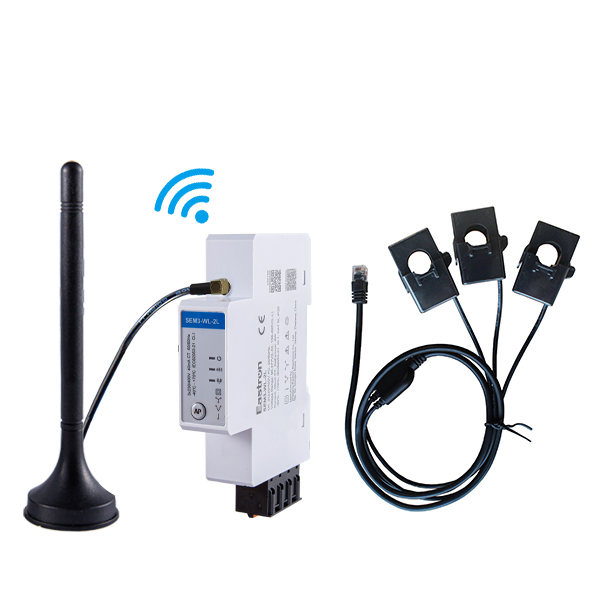
CT Type Three Phase Din Rail Wifi Energy Meter for PV Metering
May 30,2025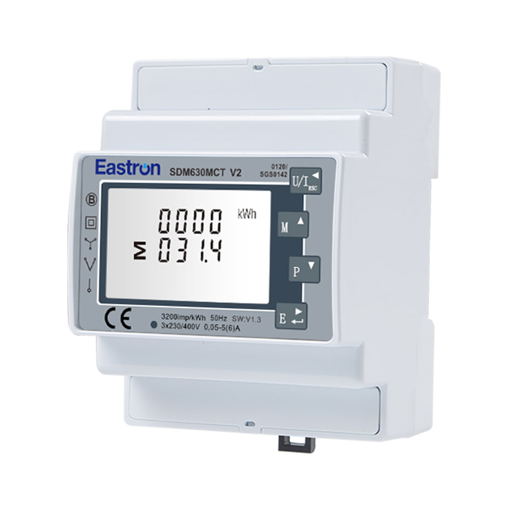
MID Approved CT Type Din Rail Three Phase Multi-function Solar PV /Zero Export Meter for PV Metering
Nov 24,2022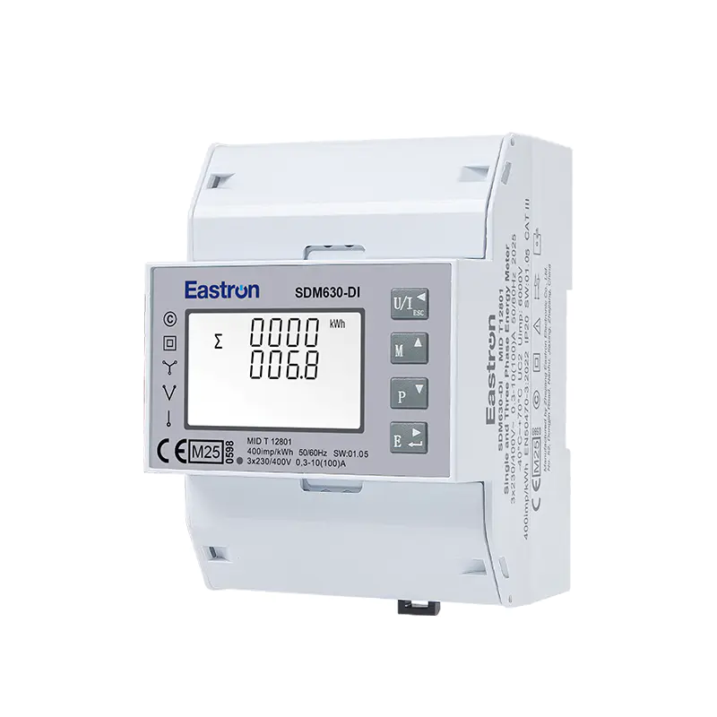
MID & UL Approved Three Phase Din Rail Type Multi-function Energy Meter for EV Charging Metering
Nov 24,2022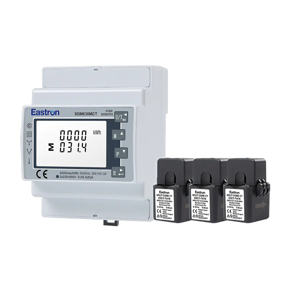
MID/UL CT Type Din Rail Three Phase Multi-function Energy Meter for EV Charging Metering
Nov 24,2022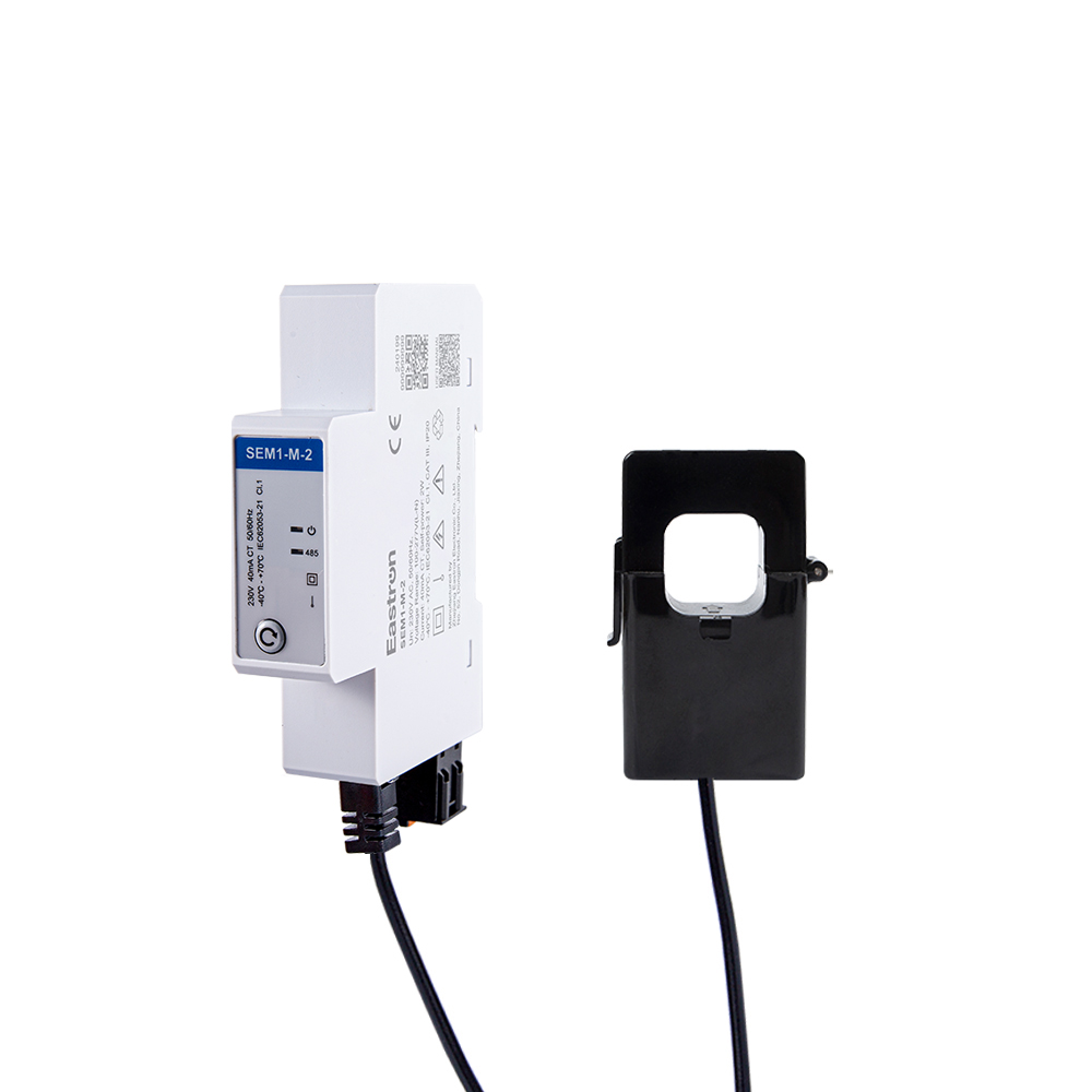
CT Type RS485 Modbus Single Phase Din Rail Energy Meter for PV Metering
May 30,2025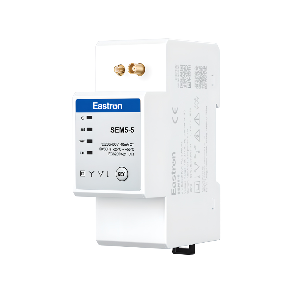
CT Operated Wireless Three Phase Energy Meter for PV Metering
May 30,2025Content
Modern electrical installations require more than a basic energy register. Commercial buildings, industrial facilities, renewable-energy systems, tenant-billing applications, and infrastructure projects increasingly need accurate measurements, remote data access, flexible current ranges, communication reliability, and straightforward installation. A connected meter must also operate within demanding electrical environments while providing data that can be used for energy management, cost allocation, fault investigation, and regulatory reporting.
The LoRaWAN CT-type DIN rail three-phase energy meter addresses these requirements by combining current-transformer measurement, multifunction electrical monitoring, pulse outputs, and long-range wireless communication in one compact device. The SDM630MCT-Lora is designed for three-phase installations using either three-phase three-wire or three-phase four-wire configurations. It can measure active and reactive energy as well as voltage, current, frequency, power factor, active power, reactive power, apparent power, and demand-related values.
Its current-transformer architecture allows the meter to be used with a wide selection of primary current ratings. Instead of forcing the entire load current through the meter terminals, the installation uses external 1 A or 5 A secondary CTs. This provides flexibility for higher-current systems and allows the same meter platform to support a broad range of electrical applications.
With a built-in LoRaWAN communication module, the meter can transmit measurement information over a long-range, low-power wireless network. It supports automatic uploading, adjustable upload and download intervals, confirmation functions, offline detection, auto-resume operation, and a broad range of regional frequency bands. These functions make it suitable for distributed metering systems where installing communication cables would be expensive, disruptive, or technically difficult.
The product is also ETL listed and MID certified, depending on the applicable configuration and market requirements. Its stated accuracy performance includes Class 0.5 active-energy measurement under the relevant standards and Class 2 reactive-energy measurement. These characteristics position the meter as a practical solution for professional energy monitoring, submetering, equipment management, and connected building applications.
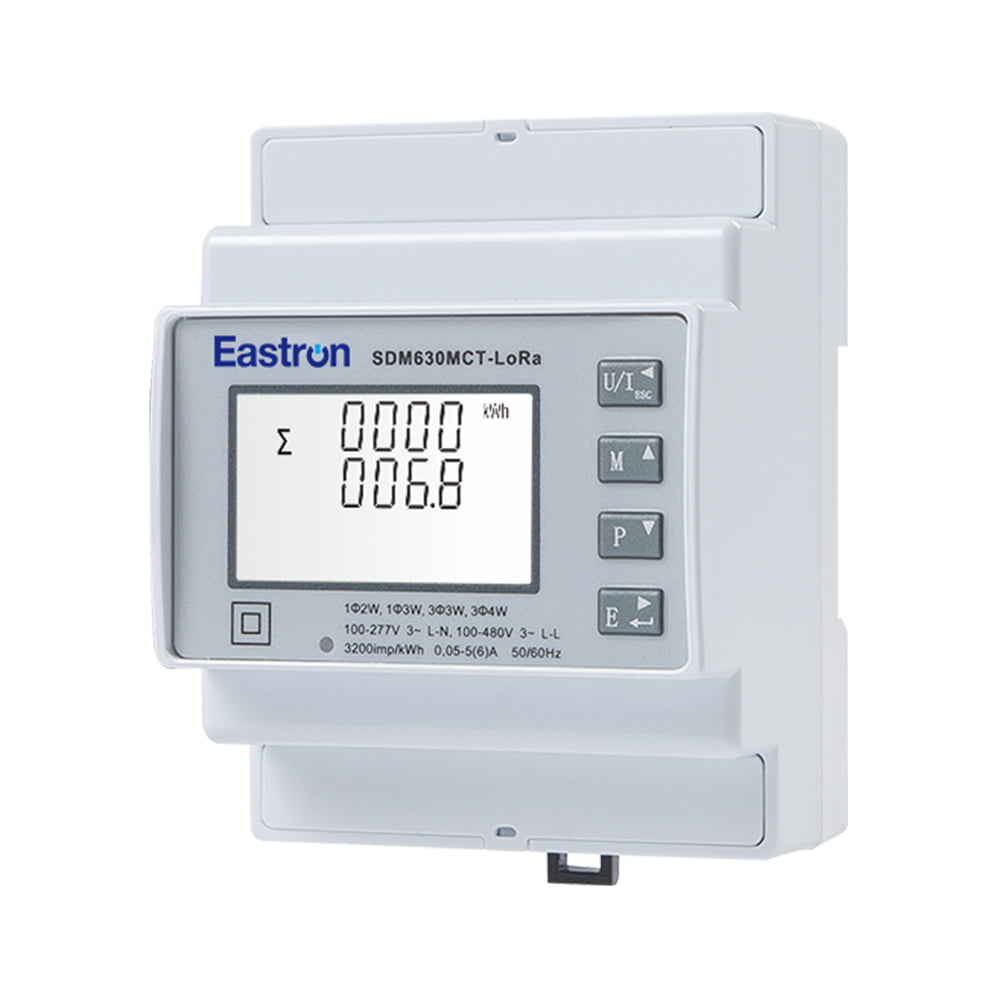
LoRaWAN CT Type Din Rail Multi-functional Three Phase ETL Energy Meter
Three-phase electrical systems are widely used in factories, commercial premises, data centers, apartment buildings, charging facilities, agricultural installations, and renewable-energy projects. A simple total kilowatt-hour value is often insufficient for understanding how these systems operate. Operators may need to know whether the phases are balanced, whether power factor is deteriorating, when peak demand occurs, and how individual loads contribute to total consumption.
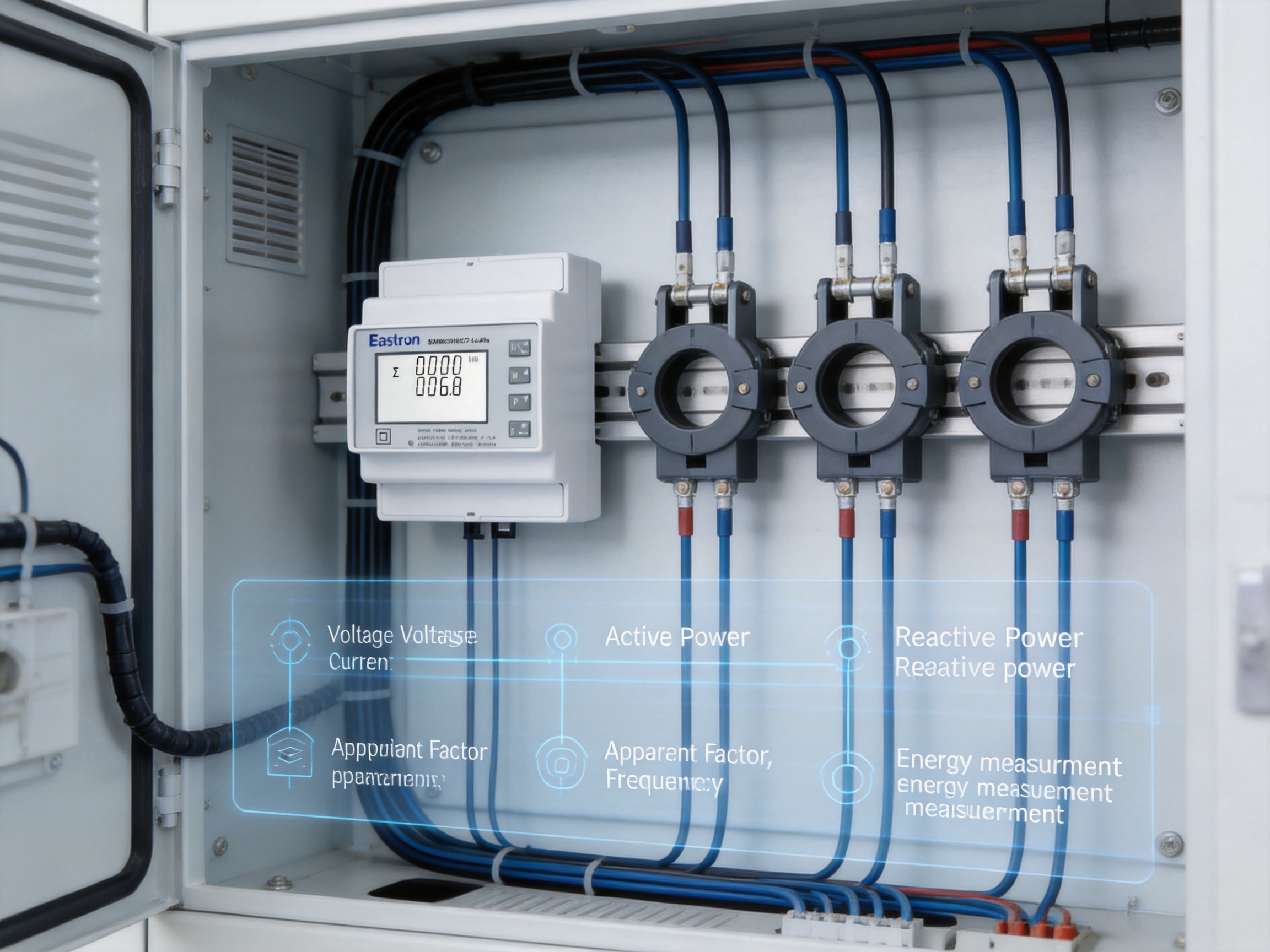
A multifunction energy meter provides a wider view of the electrical system. Voltage readings help identify supply conditions and phase irregularities. Current readings reveal the loading of feeders and equipment. Active power indicates the rate at which useful electrical energy is being consumed. Reactive power and power factor provide information about inductive loads, motor systems, transformers, and compensation equipment. Frequency measurements help verify the stability of the supply.
When these values are recorded over time, the meter becomes more than a display instrument. It becomes a source of operational intelligence. Historical data can support energy-efficiency programs, maintenance planning, equipment comparison, tenant billing, production analysis, and verification of energy-saving measures.
The value of the system increases further when measurement data is available remotely. Building managers do not need to visit every distribution board to read a display. An energy-management platform can collect measurements from multiple locations and present them in dashboards, reports, alarms, or automated control workflows.
The SDM630MCT-Lora is designed for this type of application. Its combination of local measurement and wireless communication enables both on-site access and remote data collection. The DIN rail form factor also allows the meter to be integrated into electrical cabinets without requiring a large dedicated enclosure.
The meter uses external current transformers to measure load current. The CT secondary output is connected to the meter, with supported secondary values of 1 A or 5 A. The CT primary rating can be configured from 1 A to 9999 A, giving the installation engineer flexibility to match the meter to the actual feeder or equipment rating.
Using CTs offers several important benefits. First, the meter can be applied to larger systems without passing the full primary current through the meter body. Second, the same meter model can cover many different current ranges by changing the CT selection and configuration. Third, CT installation can be convenient in existing switchboards, where conductors or busbars may already be installed and cannot easily be disconnected.
The meter supports a minimum current of 0.05 A and a starting current of 0.005 A according to the supplied specifications. These values help the device register lower levels of consumption while retaining a wide measurement range for larger loads. Correct CT selection, polarity, phase association, wiring, and configuration remain essential for accurate results.
Voltage is measured directly from the electrical system within the specified voltage range. The rated voltage is 3 × 230/400 V AC, while the supported range is 100–277 V AC line-to-neutral and 100–480 V AC line-to-line. This makes the device suitable for common low-voltage three-phase systems used in commercial and industrial environments.
The meter can measure RMS values including harmonics on three-phase AC systems. RMS measurement is important because many modern loads draw non-sinusoidal currents. Variable-speed drives, switched-mode power supplies, LED drivers, information-technology equipment, battery chargers, and power-electronic converters can all introduce waveform distortion. A meter that measures only ideal sinusoidal values may not provide a sufficiently realistic view of actual system behavior.
The principal applications are three-phase three-wire and three-phase four-wire systems. A three-phase three-wire arrangement is commonly found in delta-connected systems and certain industrial distribution networks. A three-phase four-wire arrangement includes a neutral conductor and is frequently used for mixed three-phase and single-phase loads.
Although the product description emphasizes three-phase applications, the platform documentation also references measurement of single-phase two-wire and single-phase three-wire supplies in related configurations. The exact supported wiring arrangement should always be verified against the selected model, wiring diagram, regional installation rules, and project specifications before installation.
Correct wiring is essential in CT-type metering. Each CT must correspond to the correct voltage phase, and the polarity markings must be observed. Reversed CT polarity can produce incorrect power-factor readings, negative power values, or inaccurate energy accumulation. The neutral connection, where applicable, must also be installed according to the wiring diagram.
Electrical work should be performed by qualified personnel. The installation must include suitable isolation, overcurrent protection, and safe procedures for CT circuits. A CT secondary should not be left open while the primary conductor is energized unless the CT and installation method are specifically designed for that condition. Project engineers should review the applicable electrical codes and safety requirements before commissioning.
Voltage measurement provides a direct view of supply quality and operating conditions. The meter can measure phase voltage and line-to-line voltage within its specified range. This information is useful for detecting undervoltage, overvoltage, phase imbalance, supply interruptions, and abnormal operating conditions.
Voltage trends may also help identify problems that are not immediately visible in energy totals. For example, a motor may consume an unusual amount of current because of a voltage issue, while sensitive electronic equipment may experience instability during recurring voltage disturbances. Remote voltage records can help maintenance teams investigate such events.
Current measurement is performed through external CTs. The use of configurable CT primary values makes the meter adaptable to feeders of different sizes. Current data can be used to check loading, compare phases, identify unexpected consumption, and determine whether equipment is approaching its design limits.
Phase-current comparison is particularly valuable in systems with many single-phase loads. A significant imbalance can increase neutral current, reduce equipment efficiency, and create additional heating in transformers and conductors. By collecting current data from all phases, operators can plan load redistribution more effectively.
Active power, expressed in watts or kilowatts, represents the rate at which electrical energy is converted into useful work, heat, light, or other forms of energy. Active energy, expressed in kilowatt-hours, represents accumulated consumption over time.
The meter specifies active-power accuracy of ±0.5% within the stated operating range and active-energy performance of Class 0.5 under IEC 62053-21 and Class C under EN 50470-3:2022 as provided in the product information. These specifications support professional submetering and energy-accounting applications when the device is correctly installed and configured.
Reactive power is associated with the exchange of energy between inductive or capacitive components and the electrical supply. Motors, transformers, fluorescent lighting systems, and other inductive equipment can draw reactive power. Reactive energy measurement helps operators understand the behavior of these loads and evaluate the performance of power-factor correction equipment.
The stated reactive-power accuracy is ±1% within the specified current range, while reactive energy is rated Class 2 according to IEC 62053-23. Reactive measurements can support utility-bill analysis, capacitor-bank monitoring, and the identification of inefficient operating conditions.
Apparent power represents the combined effect of active and reactive power. It is important when evaluating the capacity of transformers, switchgear, cables, and generators. A facility may have moderate active consumption but still place a high burden on electrical infrastructure if its reactive demand is significant.
Power factor indicates how effectively the supplied electrical capacity is being used. A low power factor can increase current for a given level of active power and may result in capacity problems or utility penalties. The meter specifies power-factor accuracy of ±0.01, allowing operators to monitor trends and evaluate corrective measures.
Frequency measurement can provide an additional indication of supply conditions and system stability. The product information specifies frequency accuracy of ±0.05%. Demand-related values can help users identify periods when the facility places its highest load on the supply.
Demand management is especially important for commercial and industrial users whose tariffs include peak-demand charges. By identifying when high demand occurs, operators can schedule equipment, stagger motor starts, manage charging loads, or adjust production processes.
The built-in LoRaWAN module is one of the main differences between this meter and a conventional panel meter. A traditional meter may provide a display and pulse output but require a separate communications gateway, a wired RS485 network, or manual data collection. The integrated wireless module reduces the number of components required for remote metering.
LoRaWAN is designed for long-range, low-power communication. It can be useful in locations where meters are distributed across a large property, placed in separate buildings, installed in utility rooms, or located in areas where communication cabling is difficult to route. The network approach can reduce installation disruption and simplify the expansion of a metering system.
The meter supports a wide selection of regional frequency bands, including EU868, AS923, CN433, CN470, AU915, and US902, among others. Regional frequency planning is important because radio regulations differ between countries and territories. The ability to support multiple bands helps the product serve international projects while allowing the system integrator to select the appropriate local configuration.
LoRaWAN communication also supports centralized data collection from many meters. A gateway can receive information from devices distributed throughout a facility or across multiple sites, after which the data can be forwarded to a cloud platform or local management system. This architecture is suitable for energy dashboards, automated reports, alarm systems, and portfolio-level monitoring.
Wireless communication should not be considered a replacement for proper network planning. Building materials, metal cabinets, underground rooms, geographical conditions, antenna placement, and local interference can affect radio performance. A professional deployment should include coverage testing, correct antenna positioning, appropriate gateway placement, and secure network commissioning.
The meter supports an automatic-upload mode for sending data without requiring repeated manual requests. This is important when the objective is continuous monitoring rather than occasional reading. A system can receive regular energy values, electrical parameters, status information, and other configured records.
Download and upload time intervals can be set or adjusted. Adjustable intervals allow the installation to balance data resolution, communication traffic, energy use, and storage requirements. A site focused on demand analysis may require more frequent readings, while a basic monthly submetering application may need only periodic totals.
Configurable intervals are also helpful when a project evolves. A facility may initially collect data every hour and later increase the frequency during an energy audit. Alternatively, a system may reduce communication activity after a commissioning period to optimize network resources.
Confirmation functions and offline detection provide additional operational visibility. Confirmation can help determine whether a message has been successfully received, while offline detection can alert an operator when a meter or communication path is no longer reporting. These features are valuable because a missing data stream may indicate a power interruption, network issue, gateway problem, antenna fault, or device malfunction.
The auto-resume function supports recovery after an interruption. When power or communication is restored, the meter can resume its operating mode without requiring unnecessary manual intervention. Automatic recovery is particularly useful in unmanned facilities, remote substations, distributed renewable-energy sites, and large-scale building deployments.
The product family includes configurations with two pulse outputs and RS485 Modbus, a dual-power-source option, and the LoRaWAN version with two pulse outputs plus LoRaWAN communication. Pulse outputs can be connected to external counters, building-management systems, data loggers, or legacy monitoring equipment.
Pulse interfaces remain useful even in modern wireless systems. They provide a simple way to transmit energy increments to another controller and may be required by existing infrastructure. In some applications, a pulse output can serve as an independent verification channel for the data received through a communication network.
The related RS485 Modbus configuration offers a wired option for projects that prefer local serial communication. The documented communication address range is 1–247, with transmission speeds from 1200 to 38400 bits per second. Parity can be set to none, odd, or even, and stop bits can be configured as one or two.
The stated maximum transmission distance for RS485 is up to 1000 meters under suitable installation conditions, and the response time is specified as less than 100 milliseconds. Actual performance depends on cable quality, topology, termination, electromagnetic conditions, baud rate, and network design.
The availability of multiple output configurations gives system integrators a practical choice. A small local installation may use pulse outputs. A wired building-management system may select RS485 Modbus. A distributed or retrofit project may use LoRaWAN to avoid extensive communication cabling. The common measurement platform can simplify product selection and maintenance across different projects.
Accuracy is a central consideration in energy metering. Measurement errors affect billing, energy reports, equipment comparisons, and the credibility of efficiency programs. The product specifications identify separate accuracy values for voltage, current, frequency, power factor, active power, reactive power, apparent power, active energy, and reactive energy.
| Measured Parameter | Stated Accuracy or Class | Typical Application Value |
|---|---|---|
| Voltage | ±0.2% | Supply monitoring, phase comparison, abnormal-voltage detection |
| Current | ±0.2% | Load monitoring, feeder analysis, phase balancing |
| Frequency | ±0.05% | Supply stability and system-condition monitoring |
| Power factor | ±0.01 | Power-factor correction and capacity analysis |
| Active power | ±0.5% within the stated range | Load assessment and energy-performance analysis |
| Reactive power | ±1% within the stated range | Reactive-load assessment and capacitor-bank monitoring |
| Apparent power | ±0.5% within the stated range | Transformer, generator, and switchgear loading analysis |
| Active energy | Class 0.5 IEC 62053-21; Class C EN 50470-3:2022 | Professional submetering and energy accounting |
| Reactive energy | Class 2 IEC 62053-23 | Reactive-energy tracking and operational analysis |
Standards and certifications help define the intended quality and compliance position of a meter. ETL listing indicates evaluation by Intertek for relevant requirements and is particularly significant for products entering the North American market. MID certification is relevant to regulated measurement applications in markets where the Measuring Instruments Directive applies.
Certification does not remove the need for correct installation. CT ratio settings, wiring polarity, conductor placement, voltage connections, environmental conditions, and commissioning procedures all influence practical accuracy. A certified device can only perform within its rated capability when installed according to the manufacturer’s instructions and applicable regulations.
The DIN rail design supports installation inside standard electrical distribution and control enclosures. DIN rail mounting is widely used in industrial control panels, commercial distribution boards, metering cabinets, energy-management panels, and building-automation systems.
A compact rail-mounted meter can reduce panel space requirements compared with larger standalone instruments. It can also simplify replacement and maintenance because the device fits into an established modular enclosure system. When several circuits must be monitored, multiple meters can be arranged in an organized cabinet layout.
CT-type measurement further improves installation flexibility in retrofit applications. Existing feeder conductors may be too large for direct connection to a conventional meter, or interrupting the circuit may be undesirable. External CTs can often be installed around conductors or busbars while the meter is mounted in a nearby control section.
Before installation, the engineer should verify enclosure dimensions, heat dissipation, clearances, terminal access, communication coverage, CT placement, fuse protection, and separation between power and communication wiring. The meter should be positioned where its display and connections can be accessed safely during commissioning and maintenance.
A conventional multifunction meter may require an external communication converter or a separate gateway for wireless access. The integrated LoRaWAN version reduces the number of components in the metering chain. Fewer components can simplify procurement, enclosure design, installation, and troubleshooting.
Direct meters are often restricted by their terminal current rating. The CT-type design allows the meter to work with 1 A or 5 A CT secondaries and primary ratings from 1 A to 9999 A. This makes it more adaptable to feeders with different current capacities and supports a wider range of commercial and industrial applications.
A basic energy counter may report only active energy. The SDM630MCT-Lora provides a broader set of measurements, including electrical quantities that help explain why energy is being consumed. This supports better decisions than a single cumulative kWh value can provide.
Compared with short-range wireless technologies, LoRaWAN is designed for long-range, low-power communication and can be appropriate for distributed metering. Compared with fully wired systems, wireless communication may reduce cabling requirements, particularly in retrofit projects or sites containing multiple buildings.
Automatic upload, confirmation, offline detection, and auto-resume functions improve the usability of a remote metering system. These features help operators identify communication gaps and reduce the need for manual recovery after temporary interruptions.
Support for multiple regional frequency bands and certifications such as ETL and MID helps the platform address international project requirements. The ability to select suitable communication and compliance options can reduce the need to maintain completely different meter platforms for different markets.
The manufacturer, Eastron Electronic Co., Ltd., is described as a high-tech producer of electricity meters, power analyzers, current sensors, communication modules, and energy-management products. Its product development activities cover both electrical measurement and digital communication, which is important for connected-meter applications.
A modern energy meter is not simply an electronic display. It combines voltage and current sensing, analog measurement, signal processing, energy calculation, firmware, communication protocols, wireless networking, mechanical design, insulation, thermal behavior, and regulatory compliance. A manufacturer with experience across these areas can coordinate the complete product rather than treating communication as an afterthought.
The company reports that its development teams in China and the United Kingdom work on new technologies and products. Cooperation with universities and institutions is also identified as part of its development approach. Such cooperation can support improvements in measurement algorithms, embedded software, communications, electromagnetic compatibility, and power-system analysis.
The company has established a professional laboratory capable of conducting EMC, low-voltage directive, accuracy, and environmental tests according to IEC, EN, GB, and UL standards. In-house testing capability is a significant manufacturing strength because it allows design teams to evaluate prototypes and production changes before external certification or customer delivery.
Testing across multiple categories is particularly important for a LoRaWAN CT meter. Accuracy testing verifies measurement performance. EMC testing evaluates immunity and emissions. Environmental testing examines behavior under temperature, humidity, and other conditions. Low-voltage safety testing addresses insulation and electrical protection. Wireless testing supports reliable operation within the intended regional band.
The manufacturer also reports patented technologies in software, embedded software, and hardware, as well as recognition as a high-tech enterprise and high-tech research and development center for electricity application. These capabilities suggest a product-development structure focused on both physical instrumentation and intelligent energy-management functions.
ISO 9001 quality-management practices provide a framework for controlled design, purchasing, production, inspection, corrective action, and continual improvement. Production approval by SGS according to MID standards further supports the company’s focus on regulated measurement quality. For customers, these systems can improve confidence in repeatability, traceability, and after-sales support.
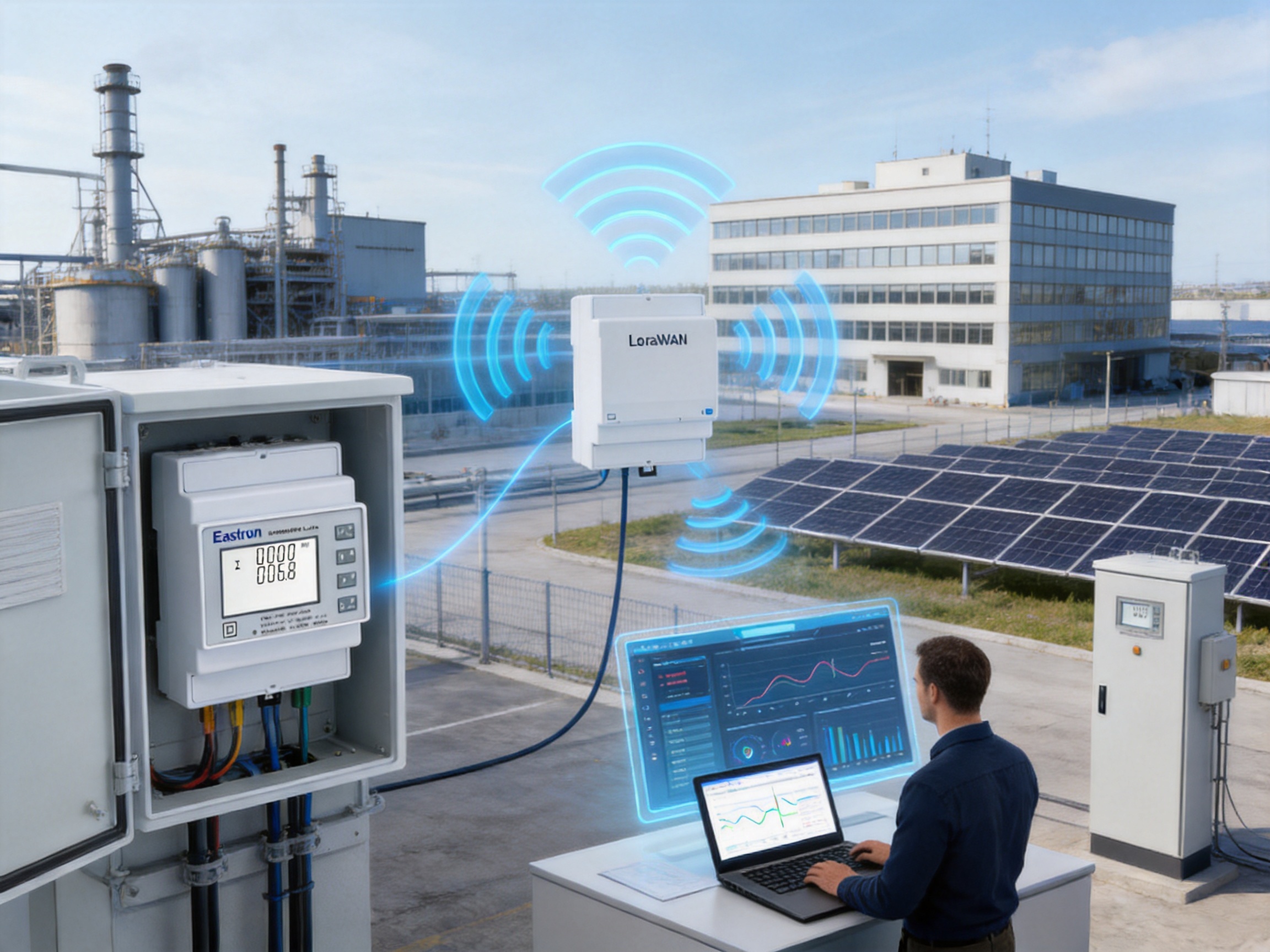
Quality control for a multifunction wireless meter must cover the entire production chain. Component selection is the first stage. Measurement components, isolation devices, microcontrollers, communication modules, terminals, relays, displays, and mechanical parts must be selected for electrical, thermal, and long-term reliability.
Incoming inspection helps ensure that components meet defined specifications before entering production. During assembly, automated or controlled processes can improve placement consistency and reduce the risk of soldering defects. Critical components may require traceability by batch, supplier, or production date.
Firmware loading and verification are essential for a connected meter. The correct software version must be installed, communication parameters must be checked, and the measurement functions must be tested. Wireless devices also require configuration of regional frequency settings and network-related parameters.
Functional testing can verify voltage channels, current channels, pulse outputs, displays, buttons, memory, communication ports, and LoRaWAN operation. Accuracy testing can compare the meter against calibrated reference equipment over relevant voltage, current, power-factor, and frequency conditions.
Safety and reliability testing may include insulation checks, dielectric withstand tests, protective-earth evaluation where applicable, temperature-rise assessment, and EMC testing. Environmental tests can help verify performance across the intended operating conditions. The exact tests depend on the product configuration, certification requirements, and destination market.
Final inspection should confirm labeling, terminal markings, packaging, documentation, accessories, and configuration records. A controlled final test helps ensure that the unit delivered to the customer matches the order and is ready for commissioning.
Commercial buildings often contain many energy-consuming systems, including lighting, air-conditioning, ventilation, elevators, pumps, kitchens, server rooms, and tenant areas. A single utility meter may not reveal how energy is distributed among these systems.
Submeters installed at major feeders can divide the facility into meaningful energy zones. The LoRaWAN meter can collect data from mechanical rooms, tenant distribution boards, retail areas, offices, parking facilities, and auxiliary buildings. Facility managers can then compare consumption patterns and identify opportunities for improvement.
Tenant billing is another possible application. When measurement accuracy, certification, installation practice, and local legal requirements are appropriate, separate meters can support allocation of energy costs among tenants or departments. Automated wireless data collection can reduce manual reading and provide a consistent record.
Power-factor and demand readings can help building operators evaluate air-conditioning systems, pumps, lifts, and other motor-driven loads. Voltage and current trends can also assist in diagnosing overloaded circuits or phase imbalance.
Industrial facilities often have complex electrical networks with production lines, motors, compressors, furnaces, welding equipment, conveyors, and process-control systems. Energy consumption may vary significantly by shift, product type, machine state, and production schedule.
Installing CT-type meters at production lines or major equipment groups allows managers to compare energy intensity. For example, the energy used per production batch can be evaluated against output. Unexpected increases may indicate equipment wear, poor operating conditions, leaks in compressed-air systems, or changes in production efficiency.
The meter’s reactive-power and power-factor readings can support motor-system analysis. Low power factor may identify a need for corrective equipment, while phase-current comparison can reveal uneven loading. Apparent-power data can help assess whether transformers and feeders have sufficient capacity for future expansion.
Wireless communication is useful when production areas are frequently modified. A wired network may require cable trays, shutdowns, or changes to control cabinets. A LoRaWAN deployment can reduce the amount of new communication infrastructure, although the wireless environment must still be evaluated carefully.
Solar installations, battery systems, microgrids, and distributed generation sites require measurement at multiple points. Operators may need to distinguish imported energy, exported energy, auxiliary consumption, inverter output, and building demand.
CT-type meters can be installed on feeders with current ratings that vary significantly from one site to another. LoRaWAN communication can connect meters located in separate electrical rooms or remote areas of a property. Regular uploads allow operators to compare generation and consumption profiles.
In renewable-energy projects, voltage, frequency, power factor, and apparent power can provide useful information about grid interaction. These values may help engineers evaluate inverter behavior, site loading, and the performance of associated equipment. The meter should be selected and configured according to the specific direction-of-energy, tariff, and regulatory requirements of the project.
Any connected energy meter should be deployed as part of a planned information system. Device identity, gateway configuration, application access, user permissions, data retention, and maintenance procedures should be defined before large-scale installation.
LoRaWAN networks typically use device and network security mechanisms, but the complete system must still be managed responsibly. Unique credentials, controlled access, secure gateway configuration, software updates, and documented commissioning records can reduce operational risk.
Network planning should consider the number of devices, upload frequency, gateway capacity, expected signal conditions, building materials, antenna positions, and future expansion. A site survey can identify weak-coverage areas before meters are installed throughout the facility.
Data quality is also part of system security and reliability. Time synchronization, correct CT ratios, device naming, phase labeling, and consistent units are necessary to prevent misleading reports. A technically secure system can still produce poor decisions if the measurement data is configured incorrectly.
A professional commissioning process should begin with a review of the electrical drawings and the meter configuration. The engineer should confirm the system type, voltage level, CT secondary rating, CT primary ratio, communication band, pulse settings, and required upload interval.
After isolation and safe installation, voltage connections and CT circuits should be checked. CT polarity and phase association must be verified. The meter should then be energized under controlled conditions, and displayed voltage and current values should be compared with expected system conditions.
Phase sequence, power direction, power factor, and active-power signs should be reviewed. If the displayed values are inconsistent with the known load, the engineer should check CT orientation, phase matching, neutral wiring, and configuration parameters before accepting the installation.
The communication system should be tested from the meter to the gateway and management platform. The test should verify device registration, message reception, timestamps, measurement mapping, alarm behavior, and offline detection. Automatic upload and auto-resume functions should also be validated where practical.
Commissioning records should include the meter serial number, installation location, CT ratio, wiring arrangement, date, responsible technician, firmware or configuration version, and test results. These records support future maintenance, audits, troubleshooting, and replacement.
Energy meters generally require less routine maintenance than mechanical equipment, but periodic review remains valuable. Operators should inspect the enclosure, terminals, CT connections, communication status, and environmental conditions. Loose terminals, excessive heat, moisture, dust, and electromagnetic interference can affect long-term performance.
Data monitoring itself can serve as a maintenance tool. A sudden loss of communication, unusual current imbalance, persistent low power factor, or unexpected energy increase may indicate a problem in the electrical system or metering installation.
Firmware and network-management procedures should be documented. Any update should be tested according to the project’s change-control process, particularly in regulated or revenue-related applications. Configuration backups can simplify recovery if a meter is replaced or reset.
Calibration and verification intervals should be determined by the application, applicable standards, customer requirements, and local regulations. Revenue or legally relevant metering may require specific verification procedures that differ from those used for general energy monitoring.
When selecting this type of meter, the first consideration is the electrical system. Confirm whether the supply is three-phase three-wire or three-phase four-wire, and verify the nominal voltage and frequency. The meter’s supported voltage range must cover the actual installation.
The second consideration is the current-transformer arrangement. Select a CT with an appropriate primary rating, a compatible 1 A or 5 A secondary, suitable accuracy, adequate insulation, and the correct physical format. The CT should be appropriate for the conductor or busbar dimensions and installation environment.
The third consideration is measurement purpose. A facility seeking general energy visibility may focus on active energy and basic power values. A site managing motors, generators, or power-factor correction may require detailed reactive, apparent, and power-factor data. A billing or regulated application should review the applicable certification and legal requirements.
The fourth consideration is communication. Determine whether LoRaWAN coverage is available, which regional frequency band applies, how many gateways are required, and how data will reach the management platform. Define the desired upload interval and the response required for offline conditions.
The fifth consideration is panel integration. Review DIN rail space, terminal arrangement, wiring access, heat dissipation, safety clearances, and communication antenna placement. A well-planned enclosure improves installation quality and future maintenance.
The SDM630MCT-Lora combines several capabilities that are often purchased separately: CT-based current measurement, three-phase multifunction monitoring, DIN rail installation, pulse outputs, long-range wireless communication, adjustable data-upload behavior, and certification-oriented accuracy.
Its flexible CT range allows the product to serve both smaller commercial feeders and larger industrial circuits, provided the selected CTs and installation design are appropriate. Its measurement functions help users move beyond simple consumption totals toward a more complete understanding of electrical performance.
The integrated LoRaWAN module is particularly valuable for projects that need remote visibility without extensive communication cabling. Automatic upload, confirmation, offline detection, and auto-resume functions address practical challenges that arise after installation, when system availability and data continuity become as important as initial measurement accuracy.
The manufacturer’s reported laboratory capability, quality-management practices, international development resources, certification experience, and broad product portfolio provide additional support for professional deployment. These strengths are relevant because a connected meter must perform consistently as part of a larger measurement solution, not only as an isolated panel instrument.
Compared with a basic pulse meter, the product offers more electrical information. Compared with a direct-connected meter, it offers greater current-range flexibility. Compared with a wired-only meter, it can simplify communication in distributed installations. Compared with a separate meter-and-wireless-converter arrangement, it integrates measurement and communication in one coordinated device.
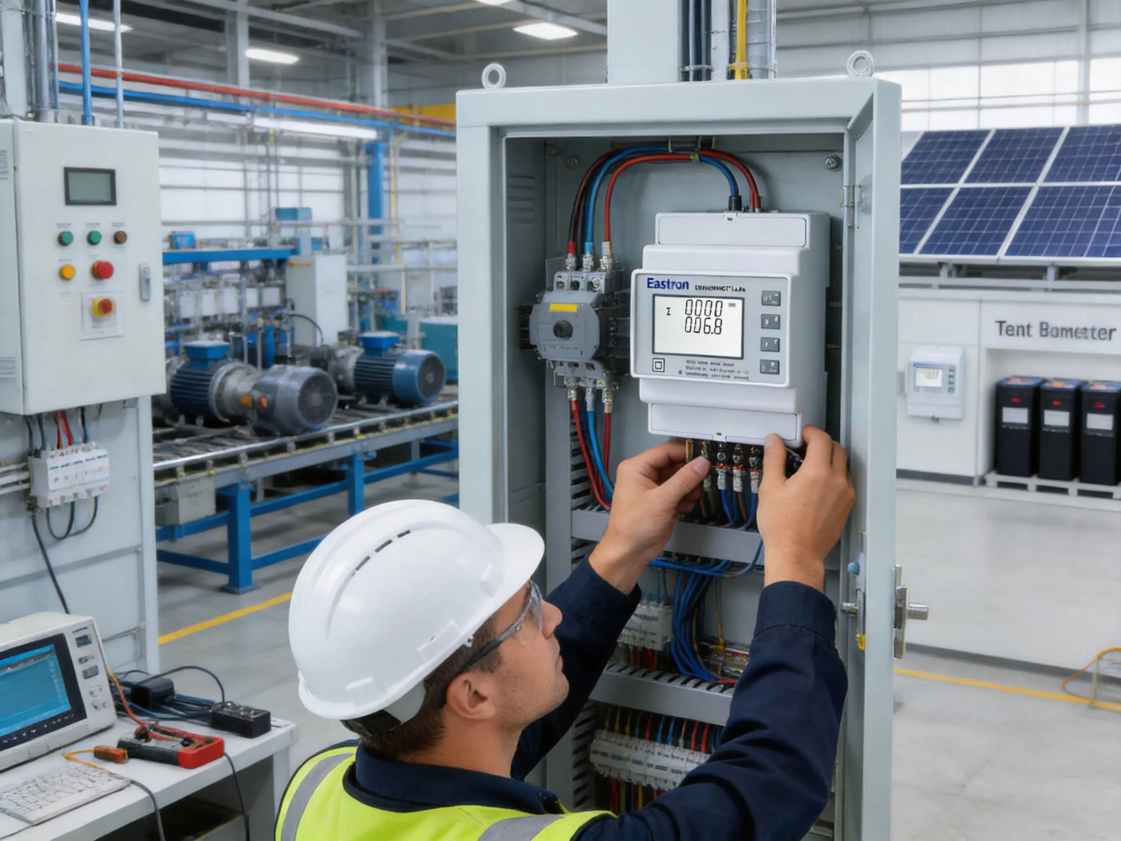
The main stated applications are three-phase three-wire and three-phase four-wire AC systems. The documentation also references related single-phase configurations within the product family. The exact model, wiring arrangement, voltage, and local installation requirements should be confirmed before deployment.
No. The SDM630MCT-Lora is a CT-type meter. It receives current signals from external current transformers with 1 A or 5 A secondary outputs. The CT primary ratio can be configured over a broad range, allowing the meter to match different feeder currents.
The supplied specifications identify a configurable CT primary range of 1–9999 A. The actual CT selected must be suitable for the electrical conductor, operating current, insulation level, accuracy requirement, and physical installation.
The meter can measure or calculate voltage, current, frequency, power factor, active power, reactive power, apparent power, active energy, reactive energy, demand-related values, and other associated electrical parameters.
The SDM630MCT-Lora includes a built-in LoRaWAN module. The product family also includes versions using RS485 Modbus and other configurations. The selected communication option should match the project’s network architecture.
The supplied information lists EU868, AS923, CN433, CN470, AU915, US902, and other regional bands. The correct band must be selected according to the country or territory where the meter will operate.
Yes. The product information states that download and upload time intervals can be set or adjusted. This enables the communication schedule to be adapted to data-resolution requirements, network capacity, and application priorities.
The meter supports confirmation functions, offline detection, and auto-resume mode. These functions help identify communication interruptions and support automatic recovery when operating conditions return to normal. The behavior of the complete system also depends on the gateway and management platform.
Its active-energy accuracy and multifunction capabilities make it suitable for many professional submetering and energy-monitoring applications. For billing or legally controlled measurement, the project must verify the required certification, installation method, verification process, and local regulations.
ETL listing indicates evaluation by Intertek against relevant requirements. It can support acceptance in markets and projects that recognize the applicable ETL certification. The exact scope of the listing should be checked against the product label, certificate, and intended installation.
MID refers to the European Measuring Instruments Directive. MID-related approval is important for certain regulated measurement applications in applicable European markets. Users should confirm whether their intended billing or legal-metrology application requires a specific MID module or verification procedure.
Yes, the CT-type and DIN rail design can be advantageous in retrofit applications. External CTs may be installed on existing conductors or busbars, while the meter is mounted in a nearby panel. The installation must still comply with electrical safety requirements and provide suitable space and access.
The product family includes versions with RS485 Modbus. The listed communication parameters include addresses from 1 to 247, baud rates from 1200 to 38400 bits per second, selectable parity, and one or two stop bits. The LoRaWAN model is specified with LoRaWAN communication and pulse outputs.
They help users understand the effect of inductive and capacitive loads on the electrical system. These values can support power-factor correction, transformer-capacity analysis, utility-cost management, and diagnosis of inefficient operating conditions.
Verify the system wiring, voltage range, CT secondary rating, CT primary ratio, CT polarity, phase association, communication band, network credentials, upload interval, pulse configuration, and safety protection. Compare displayed values with expected electrical conditions before final acceptance.
The LoRaWAN CT-type DIN rail three-phase energy meter is designed for organizations that need accurate, flexible, and remotely accessible electrical information. It combines external CT measurement with a broad range of electrical functions, including voltage, current, power, energy, reactive values, apparent power, power factor, frequency, and demand-related information.
Its integrated LoRaWAN communication, adjustable upload intervals, confirmation functions, offline detection, and auto-resume mode make it suitable for modern energy-management networks. Support for multiple regional frequency bands expands its international application potential, while ETL and MID-related qualifications support professional and regulated project requirements where applicable.
The CT architecture provides an advantage over many direct-connected meters because it accommodates a wide range of feeder currents and is well suited to retrofit installations. The DIN rail format supports organized panel integration, and pulse outputs provide compatibility with additional monitoring equipment or legacy systems.
The manufacturer’s reported laboratory resources, quality-management framework, international research cooperation, certification experience, and broad expertise in electricity products strengthen the product’s position as part of a complete measurement solution. For customers, the benefit is not only a meter that displays values, but a platform that can contribute to long-term energy visibility, operational control, and data-driven electrical management.
1. Product technical information for the SDM630MCT-Lora LoRaWAN CT-type DIN rail multifunction energy meter.
2. IEC 62053-21, Electricity Metering Equipment: Particular Requirements for Static Meters for Active Energy.
3. IEC 62053-23, Electricity Metering Equipment: Particular Requirements for Static Meters for Reactive Energy.
4. EN 50470-3:2022, Electricity Metering Equipment: Particular Requirements for Static Meters for Active Energy.
5. General principles and application practices for current-transformer-based electrical measurement.
6. General LoRaWAN network planning and deployment practices for industrial Internet of Things applications.
7. ISO 9001 quality-management principles for product design, manufacturing, inspection, and continual improvement.
8. General electrical safety practices for low-voltage distribution boards, current transformers, and DIN rail equipment.
Your email address will not be published. Required fields are marked *

We develop and produce high performance electricity meters, power analyzers, current sensors, communication modules and management systems.
Address:NO. 52, Dongjin Road, Nanhu, Jiaxing, Zhejiang, China
Copyright @ Eastron Electronic Co., Ltd. All rights reserved
