

 English
 Español
 Deutsch
 中文简体


Product Consultation
Your email address will not be published. Required fields are marked *
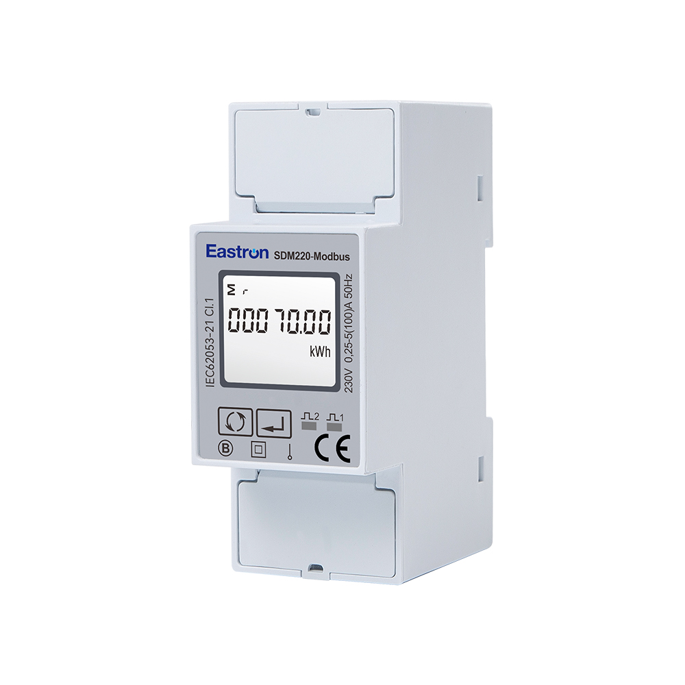
100A Single Phase Din Rail Multi-function Meter for EV Charging Metering
Aug 11,2022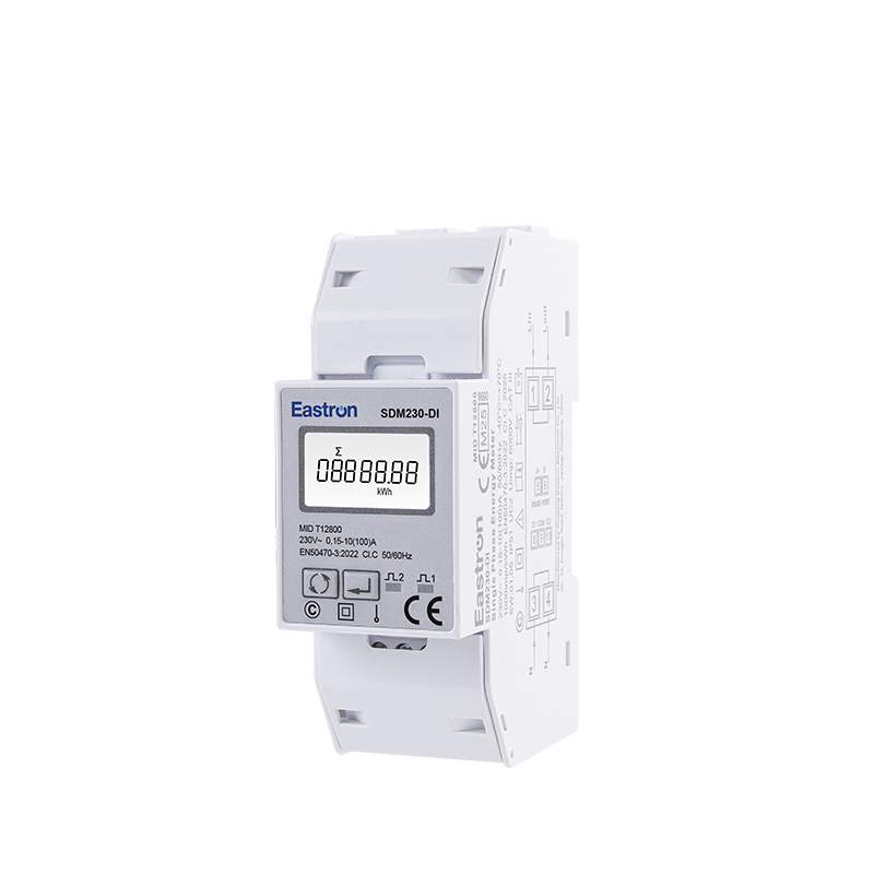
MID/ UL Approved Single Phase Din Rail Type Multi-function Energy Meter for EV Charging Metering
Nov 24,2022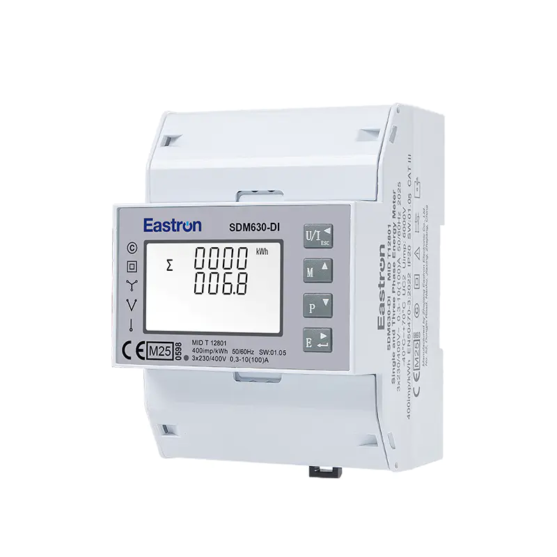
MID & UL Approved Three Phase Din Rail Type Multi-function Energy Meter for EV Charging Metering
Nov 24,2022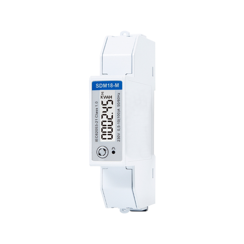
MID Approved Single Phase 100A Din Rail Type Multi-function EV meter for EV Charging Metering
Nov 24,2022
Din Rail Dual Channels DC Energy Monitoring Meter for EV Charging Metering
Aug 02,2022
Din Rail DC Energy Monitoring Meter for EV Charging Metering
Aug 02,2022Content
The rapid expansion of electric vehicle charging infrastructure has created a growing need for accurate, compact, and easily integrated electricity meters. Charging operators, equipment manufacturers, installers, property managers, and energy service providers all require reliable data about how much electricity is delivered to each charging point. That data supports billing, load management, maintenance, customer reporting, energy analysis, and compliance with applicable metering requirements.
The SDM18-M is a single-phase, two-wire, DIN rail energy meter designed specifically for applications such as 7 kW AC electric vehicle charging piles. It combines direct current measurement up to 100 A, active and reactive energy measurement, voltage and current monitoring, power factor and frequency measurement, pulse output, and RS485 Modbus RTU communication in a one-module, 18 mm-wide enclosure.
Its compact format addresses one of the most persistent challenges in modern charging equipment: providing dependable measurement without consuming valuable panel space. At the same time, its direct 100 A connection eliminates the need for external current transformers in many installations, simplifying wiring and reducing the number of components required in the distribution enclosure.
This article examines the meter’s technical characteristics, EV charging applications, communication capabilities, installation advantages, measurement performance, manufacturing strengths, and practical considerations when comparing it with alternative energy metering solutions.
MID Approved Single Phase 100A Din Rail Type Multi-function EV meter for EV Charging Metering
Electric vehicle charging is an electrical process, but it is also a metering process. A charging pile must deliver energy safely and consistently, while the operator needs to know the amount of energy transferred during each charging session. Without reliable measurement, it becomes difficult to calculate operating costs, identify abnormal consumption, allocate energy between users, or integrate the charger into a wider energy management system.
In a residential installation, a meter can help a homeowner understand the additional electricity used by an electric vehicle. In a commercial car park, the same type of device can support tenant billing or internal energy allocation. In a workplace, it can help distinguish charging consumption from the building’s general electrical load. In a fleet depot, accurate measurement can contribute to charging schedules, maintenance planning, and energy optimization.
EV charging also creates special technical requirements. Charging equipment may operate for long periods at a relatively high current. It is therefore important that the meter can handle the intended load continuously, fit within a compact enclosure, communicate with control systems, and provide stable readings under changing voltage and load conditions.
A meter designed for general building applications may offer useful functions but may not be optimized for the space constraints and direct-load requirements of a charging pile. The SDM18-M addresses these requirements with a direct 100 A input, a single-phase 1P2W configuration, a narrow DIN rail housing, and communication support intended for remote monitoring.
The SDM18-M is a multifunction single-phase energy meter for direct-connected loads. It is intended for installation on a standard DIN rail and occupies approximately one module, or 18 mm, of width. This makes it suitable for compact consumer units, EV charger control boxes, distribution boards, and other electrical enclosures where available space is limited.
The meter is designed for a single-phase, two-wire alternating-current system. Its measurement functions include active energy, reactive energy, voltage, current, active power, power factor, frequency, and demand-related values. These functions allow the meter to serve as more than a simple kilowatt-hour counter.
For EV charging, the most important operating feature is its ability to accept a direct load of up to 100 A. A typical 7 kW single-phase AC charging pile operates at a current substantially below this maximum, depending on the supply voltage and charging configuration. The additional current capacity provides operating margin and makes the meter suitable for a range of direct-connected single-phase applications.
The meter also supports RS485 communication using the Modbus RTU protocol. This allows measured values and configuration information to be exchanged with a charger controller, energy management platform, building management system, programmable logic controller, data concentrator, or other compatible supervisory device.
In addition to communication, a pulse output is available for applications that require an electrical pulse representation of energy consumption. Pulse interfaces can be useful for local counters, legacy monitoring systems, gateways, or controllers that do not use a full digital communication protocol.
| Item | Specification | Application Value |
|---|---|---|
| Electrical system | Single-phase, two-wire, 1P2W | Suitable for single-phase EV charging and general distribution circuits |
| Maximum direct current | 100 A | Allows direct connection without an external current transformer in many installations |
| Nominal current | 10 A | Reference value for the measuring system |
| Minimum current | 0.5 A | Supports measurement across a broad operating range |
| Starting current | 40 mA | Enables detection of low-load operation |
| Active energy accuracy | Class 1 IEC 62053-21; Class B EN 50470-1/3 | Supports accurate active-energy measurement for suitable applications |
| Reactive energy accuracy | Class 2 IEC 62053-23 | Provides reactive-energy information for analysis and monitoring |
| Voltage accuracy | ±0.5% | Useful for supply-quality and operating-condition assessment |
| Current accuracy | ±0.5% | Supports load monitoring and system analysis |
| Power accuracy | ±1% | Provides practical real-time power information |
| Frequency accuracy | ±0.2% | Supports electrical-system monitoring |
| Power factor accuracy | ±0.01 | Helps identify the relationship between real and apparent power |
| Communication | RS485 and Modbus RTU | Enables remote reading and system integration |
| Communication address | 1 to 247 | Allows multiple meters to operate on a shared bus |
| Transmission distance | Up to 1000 m under suitable conditions | Supports distributed installations |
| Baud rate | 1200 to 9600 bps | Provides compatibility with different host systems |
| Parity | None, odd, or even | Provides flexible serial communication configuration |
| Stop bits | 1 or 2 | Supports communication-device compatibility |
| Housing format | DIN rail, approximately 18 mm wide | Conserves enclosure space |
Many electrical meters use current transformers when the monitored circuit carries a high current. A current transformer can be valuable in large installations, but it introduces additional equipment, wiring, termination points, and installation requirements. The transformer must be correctly selected, installed in the right direction, and matched to the meter. Inaccurate transformer ratios or wiring errors can affect the quality of the final measurement.
The SDM18-M is designed for direct connection up to 100 A. In a suitable installation, this means the charging circuit can pass through the meter without an external CT. Removing the CT can provide several practical benefits.
First, direct connection reduces the number of components in the panel. Fewer components can make the enclosure easier to design and can simplify stock management for charging-equipment manufacturers. Second, it can reduce installation time because the installer does not need to mount and wire a separate transformer. Third, direct connection avoids the need to configure a transformer ratio in the meter or supervisory system.
Direct measurement can also reduce potential sources of error. A CT-based installation requires attention to primary and secondary wiring, polarity, burden, ratio, and terminal security. A direct-connected meter still requires correct wiring and suitable protective equipment, but the measurement chain is more straightforward.
The 100 A maximum should not be interpreted as permission to exceed the ratings of the conductors, protective devices, terminals, or charging equipment. The complete installation must be designed according to local electrical regulations and the ratings of every connected component. The meter is one part of a coordinated electrical system, not a substitute for circuit protection or professional design.
Space is a major design constraint in EV charging equipment. A charging pile may need to contain a residual-current protection device, miniature circuit breaker, contactor, surge protective device, control electronics, communication hardware, terminal blocks, and cable-management features. Adding a wide meter can force the designer to enlarge the enclosure or remove useful working space.
The SDM18-M occupies one approximately 18 mm module. This narrow profile allows the meter to be placed alongside other DIN rail components without making the distribution section unnecessarily large. For wall-mounted AC charging equipment, the space saving can support a slimmer enclosure and a more organized internal layout.
A compact meter is also beneficial when several charging points are installed together. Each charging circuit may require individual measurement, and the cumulative width of conventional meters can quickly become significant. A narrow meter makes it more practical to provide channel-level measurement in multi-charger installations.
Compactness must not come at the expense of usability. The meter therefore needs clearly identified terminals, an installation format familiar to electricians, and a communication arrangement that can be connected without excessive congestion. DIN rail mounting provides a widely recognized mechanical approach and helps simplify replacement or servicing.
A basic energy counter reports accumulated kilowatt-hours. That information is essential, but it may not be sufficient for troubleshooting or system optimization. The SDM18-M provides a broader set of electrical measurements, allowing the operator to see how the charging circuit is behaving in real time.
Active energy is the primary measurement for most EV charging applications. It represents the electrical energy consumed by the load over time and is commonly expressed in kilowatt-hours. Active-energy data can be used for cost allocation, customer statements, charger performance analysis, and comparison with utility records.
The stated active-energy performance includes Class 1 under IEC 62053-21 and Class B under EN 50470-1/3. These classifications provide a recognized basis for evaluating measurement performance. The applicable classification and legal use of the meter should always be confirmed against the requirements of the target market and the specific billing arrangement.
Reactive energy is associated with the exchange of energy between inductive or capacitive components and the electrical supply. Although many small AC EV charging loads are primarily evaluated by active energy, reactive-energy information can still be useful in larger facilities or installations that include other equipment.
Monitoring reactive energy may help operators understand power-quality conditions, investigate unusual load behavior, or assess the overall electrical profile of a site. The meter provides reactive-energy measurement according to the stated Class 2 performance under IEC 62053-23.
Voltage and current readings provide immediate context for energy consumption. If a charger is operating below its expected power level, the operator can examine whether the cause is reduced current, a supply-voltage issue, control-system behavior, or the vehicle itself.
Current information is also useful for load management. A system can compare the current drawn by several charging points and determine whether a distribution board is approaching its design limit. Voltage information can assist with identifying supply variation, phase issues in broader systems, or abnormal operating conditions.
Real-time power measurement indicates how much power the charging circuit is using at a particular moment. This is valuable when coordinating charging with building demand, solar generation, battery storage, or a site-level power limit.
Power factor describes the relationship between active power and apparent power. Although the power factor of a modern electronic charger may vary according to its internal design and operating point, monitoring this value provides additional insight into the electrical load. A significant change in power factor may prompt further investigation of the charger, supply, or connected equipment.
Frequency measurement can support general supply monitoring. It can help a supervisory platform record the condition of the electrical network and identify deviations that may require attention.
Demand-related information is useful for facilities that are charged according to maximum demand or that need to control their peak load. When integrated with a broader energy management system, demand data can support strategies such as staggered charging, current limiting, and scheduled operation.
Modern charging infrastructure increasingly depends on data exchange. A meter that can only display readings locally may be adequate for a small standalone installation, but networked charging systems generally require an accessible communication interface. The SDM18-M provides RS485 communication using Modbus RTU, a widely used industrial protocol.
RS485 is suitable for connecting devices over relatively long distances and for operating multiple devices on a shared communication bus. Under suitable cable, grounding, termination, and installation conditions, the stated transmission distance can reach up to 1000 meters. Actual performance depends on cable quality, electromagnetic conditions, network topology, baud rate, and the design of the host system.
Modbus RTU allows a controller to request measurement values from the meter. Depending on the implementation and register map, a monitoring system may read accumulated active energy, reactive energy, voltage, current, power, power factor, frequency, demand values, and configuration parameters.
The communication address range of 1 to 247 allows multiple meters to be connected to a single RS485 network, provided each device has a unique address. This is particularly useful in car parks, apartment developments, commercial facilities, and fleet depots where several charging points are monitored by one gateway or management controller.
The available baud rates range from 1200 to 9600 bps. The meter also supports selectable parity options and one or two stop bits. These settings help the device adapt to the communication requirements of different controllers and gateways. All devices on the same serial network must use compatible communication parameters.
For dependable communication, installers should observe common RS485 practices. The cable should be suitable for the environment, the bus should use an appropriate line topology, polarity should be maintained, and termination should be applied where required by the network design. Communication wiring should also be separated from high-current conductors where practical to reduce the risk of interference.
Although Modbus is the primary communication method for many modern systems, pulse output remains useful. Pulse outputs provide a simple representation of energy accumulation and can be connected to compatible counters, data loggers, building controllers, or older monitoring equipment.
A pulse-based system can be useful when the host controller does not include a Modbus interface or when a simple energy total is sufficient. It can also provide an independent signal path for verification or local monitoring. The pulse constant, electrical characteristics, and receiving-device requirements should be confirmed before installation.
Using both digital communication and pulse output can provide flexibility during system development. A manufacturer may use Modbus for detailed readings during commissioning while using the pulse output for a separate energy display or supervisory counter. This flexibility can help integrators adapt the meter to different project requirements without changing the basic hardware.
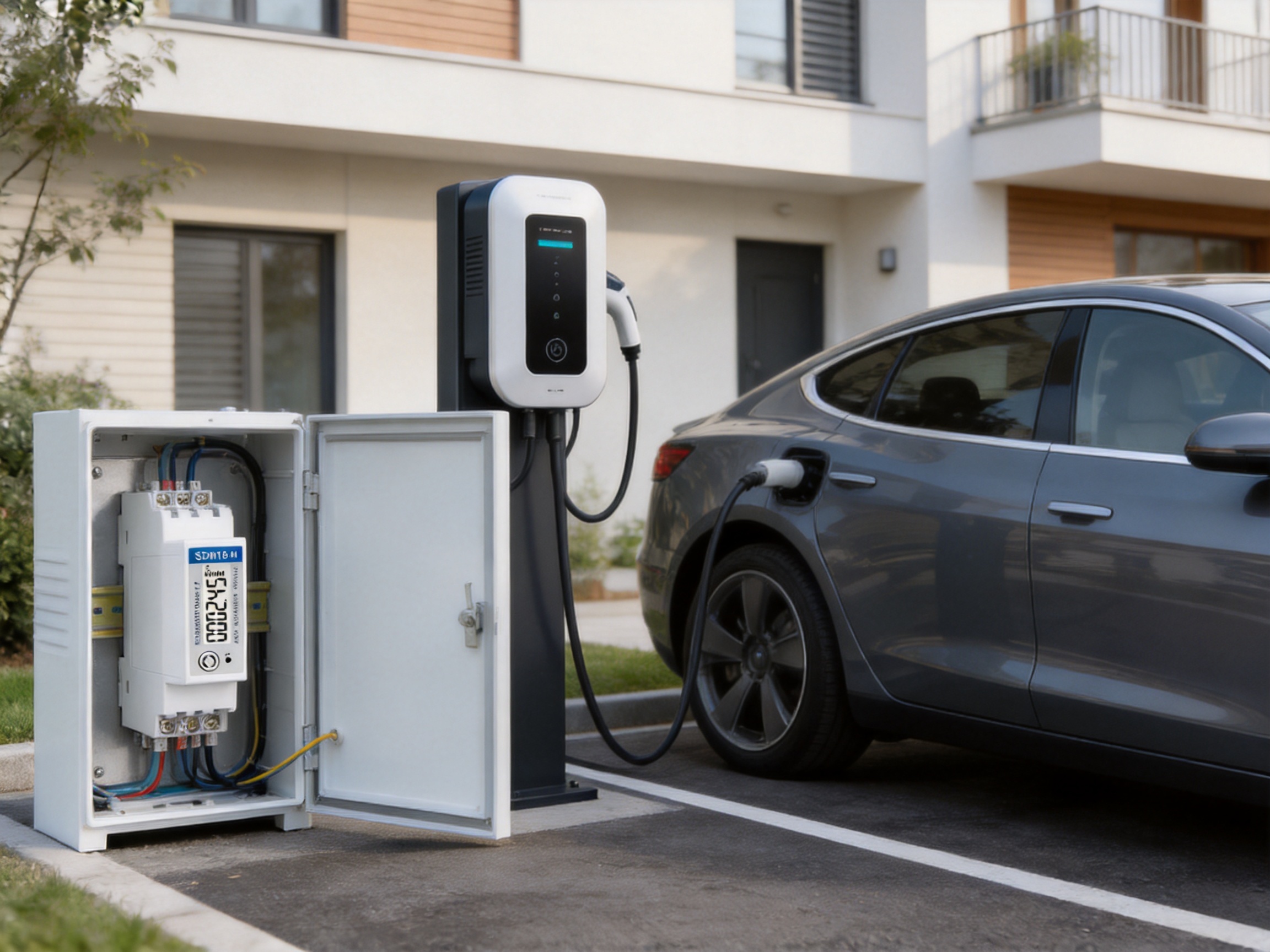
A 7 kW AC charging pile is a common configuration for residential, workplace, hospitality, and light-commercial applications. The charger typically supplies energy to the vehicle’s onboard charger rather than converting all charging power internally. The charging current is managed according to the vehicle, the charger settings, and the available supply capacity.
The SDM18-M is suitable for monitoring the electrical input associated with this type of single-phase charging equipment. Its direct 100 A capacity provides considerable headroom relative to a typical 7 kW operating current, while the compact housing allows it to fit into the charger’s internal distribution section.
In a residential application, the meter can report the energy consumed by the charger separately from the rest of the home. In a workplace, it can help calculate the energy used by employees’ vehicles. In a hospitality or retail environment, it can support charger usage analysis. In a managed apartment complex, it can provide individual or shared charging data for residents.
The meter can also be used in charging equipment connected to a local energy management system. For example, a building controller may read the charger’s present power and reduce or delay charging when the building approaches a predefined demand limit. If on-site solar power is available, the system may use meter data to coordinate charging with solar generation.
Bidirectional measurement is relevant to systems in which energy may flow in more than one direction. Conventional EV charging transfers energy from the electrical network to the vehicle. However, emerging applications may include vehicle-to-home, vehicle-to-building, or vehicle-to-grid functions, depending on the charger design, vehicle capabilities, regulatory framework, and control system.
A bidirectional meter can distinguish or account for energy flowing toward and away from the load. This can provide a more complete picture of the electrical exchange at the charging point. It may also be useful in systems that include battery storage, inverter equipment, or other sources of reverse energy flow.
The exact interpretation of imported and exported energy depends on the meter configuration, register definitions, and application software. System designers should confirm how the host controller reads and records the relevant values before deploying the meter in a bidirectional billing application.
Accuracy is a central consideration when selecting an energy meter. A measurement device used for monitoring may have different requirements from a device used for formal transaction billing. The applicable standards, approval conditions, installation environment, load profile, and legal framework all need to be considered.
The SDM18-M is described as MID approved and provides active-energy performance associated with Class B under EN 50470-1/3. It also specifies Class 1 active-energy performance under IEC 62053-21. These standards provide recognized technical frameworks for evaluating electricity meters.
Accuracy is influenced by more than the meter’s declared class. Correct installation, conductor sizing, terminal tightness, environmental temperature, electromagnetic conditions, supply quality, and the operating range all affect the result. A high-quality meter cannot compensate for incorrect wiring or an unsuitable installation.
For formal billing or regulated applications, the project owner should verify that the exact product variant, approval documentation, firmware configuration, sealing arrangements, and installation method satisfy local requirements. National implementation rules can differ, and approval in one market does not automatically establish compliance in every jurisdiction.
Compared with a CT-based meter, a direct-connected meter can reduce component count and installation complexity for circuits within its current rating. This can be especially advantageous in compact EV chargers where internal space is limited.
Compared with wider multifunction meters, the approximately 18 mm DIN rail format conserves panel space. This can reduce enclosure size or leave additional room for circuit protection and communication equipment.
Compared with a simple kilowatt-hour counter, the multifunction design provides voltage, current, power, power factor, frequency, reactive energy, and demand-related information. This broader data set helps with commissioning, troubleshooting, optimization, and remote diagnostics.
Compared with meters that provide only a local display or pulse output, the combination of RS485 Modbus RTU and pulse output gives equipment manufacturers more choices. The device can be connected to an intelligent charger controller, a gateway, a building management system, or a simpler pulse-reading device.
Compared with standalone meters intended for isolated use, the configurable Modbus address and shared RS485 architecture are useful when multiple chargers must be monitored from a central location. This can support scalable charging infrastructure without requiring a separate communication architecture for every meter.
Compared with meters designed only for conventional import measurement, bidirectional capability provides greater flexibility for energy systems involving reverse flow, storage, or future vehicle-to-building applications.
These advantages do not mean that one meter is suitable for every application. Three-phase charging, very high-current installations, CT-based measurement systems, revenue-metering projects with specialized national requirements, and installations with unusual environmental conditions may require different equipment. The correct comparison must consider the complete technical specification rather than a single feature.
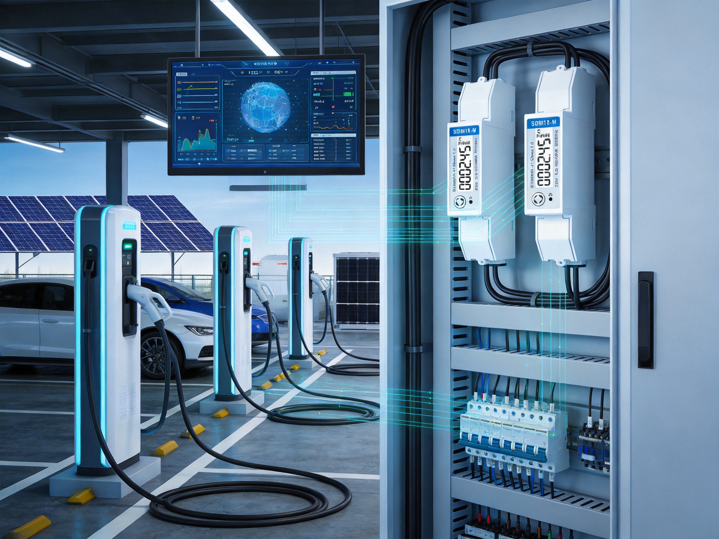
The performance of an energy meter depends on its electronic design, firmware, sensors, mechanical construction, calibration process, production controls, and final inspection. A product specification is important, but the manufacturer’s ability to produce that specification consistently is equally significant.
Eastron Electronic Co., Ltd. develops and manufactures electricity meters, power analyzers, current sensors, communication modules, and energy management products. Its product range covers measurement equipment for residential, commercial, industrial, and specialized applications, including EV charging metering.
The company’s engineering activities span hardware, embedded software, communication functions, measurement algorithms, and product integration. This broad capability is valuable because modern meters are not merely passive electrical instruments. They are connected devices that must combine precision measurement with reliable data processing and communication.
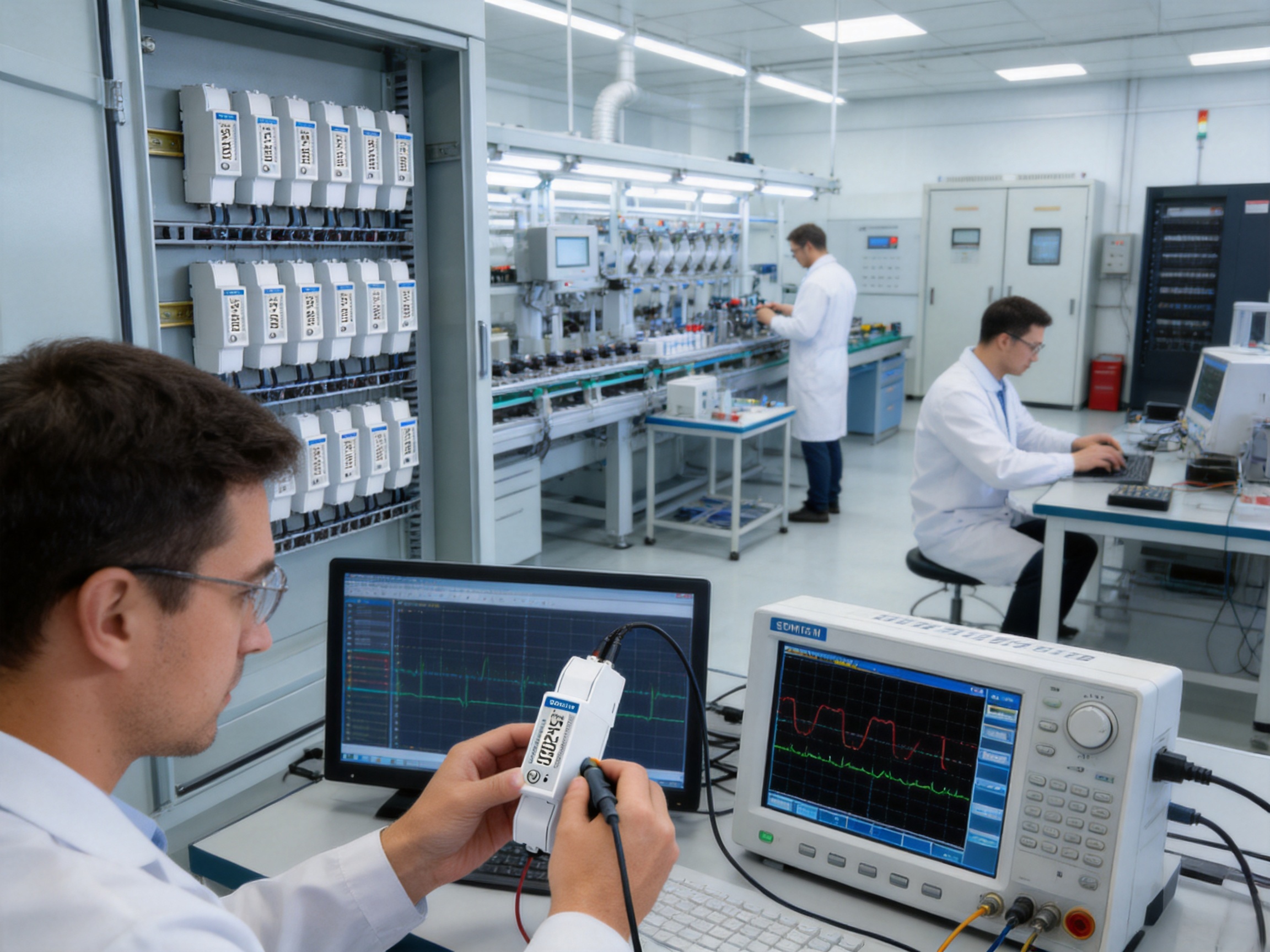
The company operates a professional laboratory capable of carrying out EMC, low-voltage, accuracy, and environmental tests in accordance with relevant IEC, EN, GB, and UL requirements. Such facilities support product development, design verification, production validation, and ongoing quality control.
Accuracy testing is particularly important for electricity meters. A production line must verify that units remain within their specified performance range across appropriate voltage, current, power factor, and frequency conditions. Calibration and test procedures help identify component variation, assembly problems, sensor errors, communication faults, and firmware issues before products are shipped.
Environmental testing is also important because meters may be installed in outdoor charging equipment, utility rooms, garages, parking structures, or industrial enclosures. Temperature variation, humidity, electrical interference, vibration, and long operating periods can all influence reliability. Testing helps engineers evaluate how the design performs beyond ideal laboratory conditions.
EV charging environments can contain contactors, switching power supplies, inverters, communication devices, and high-current conductors. These components may generate conducted or radiated interference. Electromagnetic compatibility testing helps assess whether the meter can operate correctly in the presence of expected disturbances and whether it produces unacceptable interference itself.
Low-voltage and electrical safety testing supports evaluation of insulation, clearances, creepage distances, dielectric performance, protective arrangements, and other safety-related characteristics. The exact tests depend on the product design and target-market standards, but a controlled laboratory provides a structured environment for verification.
The company has development teams in China and the United Kingdom and continues to invest in new technologies and product development. International engineering resources can support broader understanding of regional standards, customer requirements, communication platforms, and application trends.
Electricity measurement is changing rapidly. Customers increasingly expect meters to support remote access, real-time data, flexible integration, smaller form factors, and compatibility with energy management systems. Continuous research and development allows a manufacturer to respond to these requirements while maintaining attention to measurement accuracy and product reliability.
The company follows an ISO 9001 quality management system. A formal quality system helps establish controlled procedures for design, purchasing, production, inspection, documentation, corrective action, and customer support.
Quality management is especially important for meters used in large charging deployments. A project may require hundreds or thousands of devices with consistent firmware, communication behavior, mechanical dimensions, and measurement performance. Controlled processes help reduce variation between production batches and simplify field deployment.
The company holds patented technologies in software, embedded software, and hardware. Patents alone do not guarantee product suitability, but they indicate ongoing investment in technical development. In a multifunction meter, embedded software is responsible for processing measurement signals, calculating electrical values, managing communication, storing energy data, and controlling user settings.
Hardware and firmware must work together accurately. The sensing circuit, analog-to-digital conversion, microcontroller, memory, communication interface, power supply, and enclosure all contribute to the final product. Integrated development experience can help the manufacturer optimize these elements as a complete system.
Installation should be performed by qualified personnel in accordance with local electrical regulations and the charger manufacturer’s instructions. Before work begins, the circuit must be isolated and verified as de-energized. The meter must be installed with suitable protective devices, conductors, terminals, and enclosure conditions.
The single-phase two-wire configuration should be confirmed before connection. Line and neutral conductors must be connected to the correct terminals, and the load side should be wired according to the approved wiring diagram. Incorrect polarity, loose terminals, or unsuitable conductor sizes can create safety hazards and measurement errors.
The maximum direct current rating must be considered together with ambient temperature and enclosure conditions. The current capacity of the meter does not override the ratings of the circuit breaker, cable, contactor, charger connector, or distribution equipment.
During commissioning, the installer should verify voltage readings, current readings, accumulated energy, communication parameters, device address, and pulse behavior where applicable. If the meter is connected to an energy management system, the register map and scaling factors should be checked carefully.
RS485 networks should be commissioned systematically. The installer should confirm A and B polarity, unique device addresses, matching baud rates, compatible parity and stop-bit settings, correct cable termination, and appropriate shielding or grounding practices. Communication should be tested both with a single device and with the complete network when multiple meters are connected.
The meter should not be installed in an environment outside its declared operating conditions. Excessive heat, condensation, aggressive chemicals, strong vibration, water ingress, or severe electromagnetic interference can reduce service life or affect performance. The enclosure should provide an appropriate level of environmental protection for the installation location.
An EV charger becomes more valuable when its measurement data is connected to a broader energy platform. The SDM18-M can provide data to systems that monitor building demand, coordinate distributed charging, analyze user consumption, or report energy performance.
In a load-balancing application, the controller can read the current and power of each charger and compare the total with the site limit. If the total approaches the available capacity, the controller may reduce charging current or sequence the charging sessions.
In a solar-powered facility, the controller may compare charger demand with solar generation. During periods of high renewable output, the system may allow greater charging power. When solar output falls, charging can be reduced or scheduled for a later time. The meter does not make these decisions independently, but it provides the electrical information needed by the control system.
For facility reporting, accumulated energy values can be collected at regular intervals. This supports monthly analysis, equipment comparison, maintenance planning, and sustainability reporting. A central platform can also generate alarms when power, current, voltage, or communication behavior differs from expected conditions.
Solid-state energy meters generally require less routine maintenance than mechanical metering equipment, but periodic inspection remains advisable. Maintenance teams should check terminal tightness, enclosure condition, signs of overheating, communication stability, and consistency between meter readings and other system data.
Unexpected energy readings may result from wiring errors, incorrect register interpretation, charger behavior, vehicle charging limitations, sensor problems, or software scaling factors. Troubleshooting should begin by comparing the meter’s voltage and current readings with independent measurements where appropriate.
Communication faults should be investigated separately from measurement faults. A meter may continue measuring correctly while a damaged RS485 cable, incorrect address, incompatible serial settings, or gateway problem prevents data from reaching the monitoring platform.
Firmware and configuration management should be controlled in larger installations. Devices should be documented by location, address, circuit, and installation date. A clear record helps technicians identify the correct meter during maintenance and prevents duplicate addresses when equipment is replaced.
Before selecting the SDM18-M or any comparable meter, project designers should define the electrical system, expected load, measurement purpose, communication requirements, environmental conditions, and regulatory obligations.
The first question is whether the installation is single-phase, two-wire. If the charging system is three-phase, a three-phase meter is normally required. The second question is whether the maximum current falls within the direct-connected range. If the current exceeds 100 A or the project specifically requires CT measurement, a different configuration may be more appropriate.
The designer should then determine whether the meter is intended for internal monitoring, customer cost allocation, or regulated billing. These use cases may involve different accuracy, certification, sealing, data retention, and verification requirements.
Communication planning is equally important. The designer should identify the host controller, protocol requirements, cable route, number of devices, maximum distance, network topology, and gateway arrangement. If a pulse output is preferred, the receiving device must be compatible with the meter’s pulse characteristics.
Finally, the enclosure layout should be reviewed. The one-module width can offer significant benefits, but there must still be enough space for safe conductor routing, terminal access, heat dissipation, protective devices, and service operations.
The meter is designed for a single-phase, two-wire AC system, identified as 1P2W. It is suitable for single-phase charging circuits and other compatible single-phase loads.
The maximum stated direct current is 100 A. This allows the meter to be connected directly to suitable circuits without an external current transformer, provided the complete installation is correctly designed and remains within all applicable ratings.
Yes. The product is intended for monitoring the energy consumption of 7 kW AC EV charging piles. Its 100 A direct-current capability provides substantial capacity for this type of application.
No external CT is normally required for direct-connected loads within the meter’s specified current range. CTs may still be required for applications outside that range or for systems designed around transformer-based measurement.
The meter measures or calculates active energy, reactive energy, voltage, current, power, power factor, frequency, and demand-related values. The exact values available to a host system depend on the product register map and configuration.
Yes. The meter provides RS485 communication using Modbus RTU. It can be connected to compatible controllers, gateways, energy management systems, and building management platforms.
The communication address range is 1 to 247, allowing multiple meters to be identified on a shared network. The practical number of devices depends on the host system, bus design, cable conditions, polling interval, and communication requirements.
The product supports bidirectional measurement. This can be useful in applications involving reverse energy flow, energy storage, or future vehicle-to-building and vehicle-to-grid configurations. Register definitions and application settings should be verified before deployment.
MID refers to the European Measuring Instruments Directive framework. The supplied product information identifies the meter as MID approved. However, project owners should confirm that the exact model variant and installation method satisfy the legal metering requirements of the intended country and billing application.
The meter supports baud rates from 1200 to 9600 bps, communication addresses from 1 to 247, none, odd, or even parity, and one or two stop bits. All devices on a shared network must use compatible settings.
The stated maximum transmission distance is 1000 meters under suitable conditions. Actual distance depends on cable type, topology, termination, electromagnetic interference, baud rate, grounding, and the quality of the installation.
An approximately 18 mm width allows the meter to occupy one DIN rail module. This saves space in EV charger enclosures and distribution boards, especially when several charging circuits must be measured independently.
It may be suitable for certain billing-related applications when the relevant approval, accuracy, installation, sealing, software, and national regulatory requirements are satisfied. The project owner should verify the complete legal and technical requirements before using it for formal customer billing.
The pulse output provides an electrical pulse representation of energy accumulation. It can be connected to compatible counters, data loggers, controllers, or monitoring systems that do not use Modbus communication.
Installation should be performed by qualified electrical personnel familiar with EV charging systems, DIN rail equipment, circuit protection, and RS485 communication. Local regulations and the manufacturer’s wiring instructions must be followed.
The SDM18-M combines the essential functions required for compact single-phase EV charging measurement. Its ability to measure up to 100 A directly, fit within approximately one 18 mm DIN rail module, communicate through RS485 Modbus RTU, provide pulse output, and support bidirectional measurement makes it a flexible option for 7 kW AC charging applications.
Its multifunction design provides more useful information than a basic energy counter. Voltage, current, power, power factor, frequency, reactive energy, and demand-related measurements can help operators understand charger behavior and integrate charging equipment into wider energy management systems.
The product’s advantages are strengthened by the manufacturer’s experience in electricity measurement, embedded technology, communications, testing, and quality management. Laboratory capabilities covering accuracy, EMC, low-voltage, and environmental testing support the development and production of reliable metering products.
For equipment manufacturers, the direct-connected architecture can simplify charger design and reduce the need for external current transformers. For installers, the narrow DIN rail housing can make panel assembly more efficient. For operators, communication and multifunction measurement can improve visibility into energy use. For system integrators, the combination of Modbus RTU, configurable serial settings, and bidirectional measurement provides useful flexibility.
As with any electrical measuring device, successful deployment depends on correct application selection, wiring, protection, commissioning, communication configuration, and compliance verification. When these factors are properly addressed, a compact 100 A DIN rail meter can provide a practical foundation for accurate and connected EV charging energy management.
IEC 62053-21, Electricity Metering Equipment, Particular Requirements for Static Meters for Active Energy.
IEC 62053-23, Electricity Metering Equipment, Particular Requirements for Static Meters for Reactive Energy.
EN 50470-1, Electricity Metering Equipment, General Requirements, Tests and Test Conditions.
EN 50470-3, Electricity Metering Equipment, Particular Requirements for Static Meters for Active Energy.
Modbus Organization, Modbus Application Protocol Specification.
Modbus Organization, Serial Line Protocol and Implementation Guide.
ISO 9001, Quality Management Systems, Requirements.
European Union, Measuring Instruments Directive, General Framework for Regulated Measuring Instruments.
Manufacturer technical information for the SDM18-M single-phase multifunction EV charging meter.
Your email address will not be published. Required fields are marked *

We develop and produce high performance electricity meters, power analyzers, current sensors, communication modules and management systems.
Address:NO. 52, Dongjin Road, Nanhu, Jiaxing, Zhejiang, China
Copyright @ Eastron Electronic Co., Ltd. All rights reserved
