

 English
 Español
 Deutsch
 中文简体


Product Consultation
Your email address will not be published. Required fields are marked *
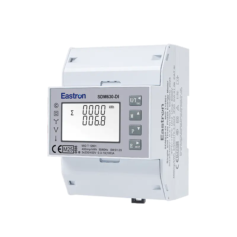
MID & UL Approved Three Phase Din Rail Type Multi-function Energy Meter for EV Charging Metering
Nov 24,2022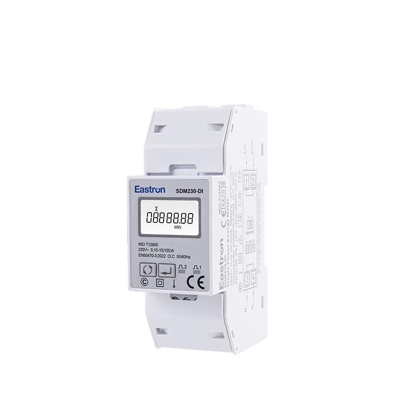
MID/ UL Approved Single Phase Din Rail Type Multi-function Energy Meter for EV Charging Metering
Nov 24,2022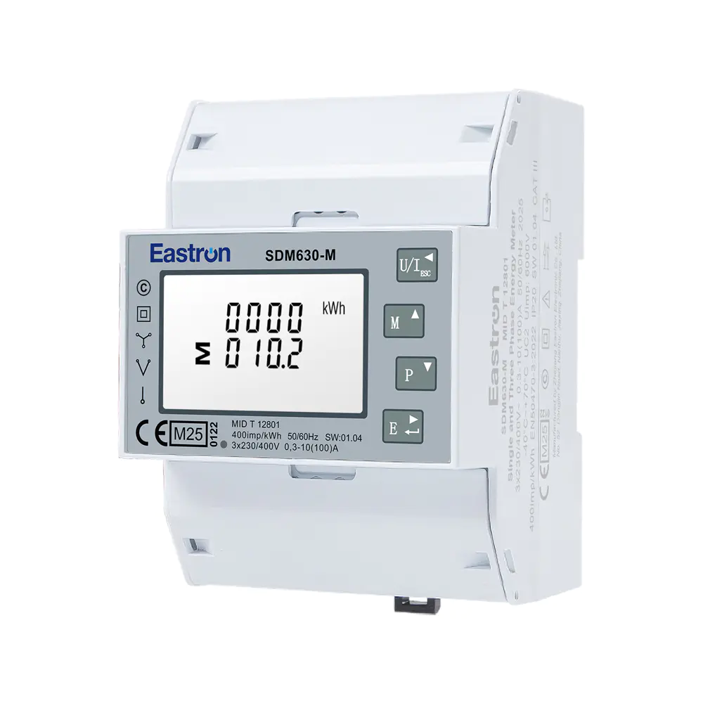
MID UL Certified Din Rail Three Phase Multi-function Energy Meter for EV Charging Metering
Aug 02,2022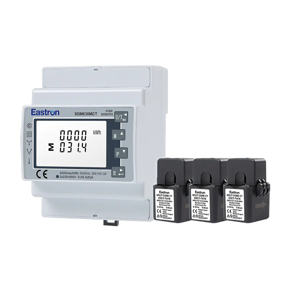
MID/UL CT Type Din Rail Three Phase Multi-function Energy Meter for EV Charging Metering
Nov 24,2022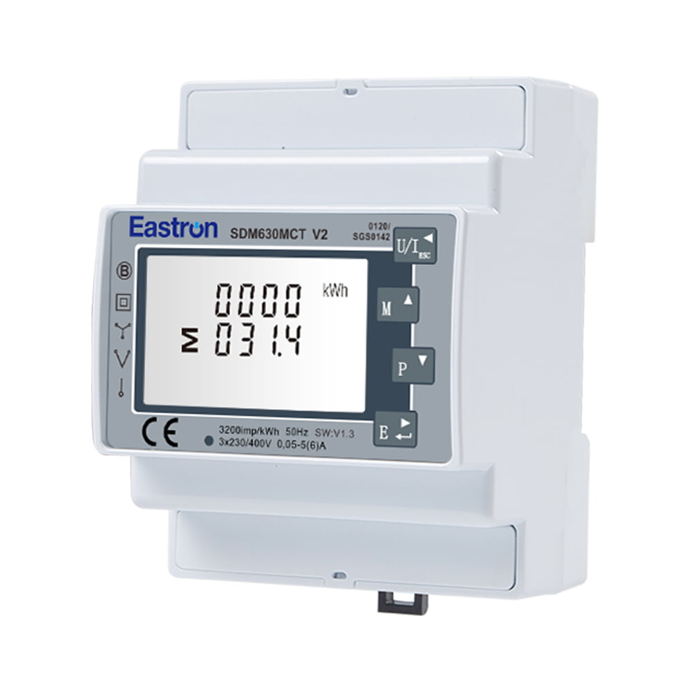
MID Approved CT Type Din Rail Three Phase Multi-function Solar PV /Zero Export Meter for PV Metering
Nov 24,2022
MID Din Rail Type Single Phase Multi-function Energy Meter for EV Charging Metering
Jul 26,2022Content
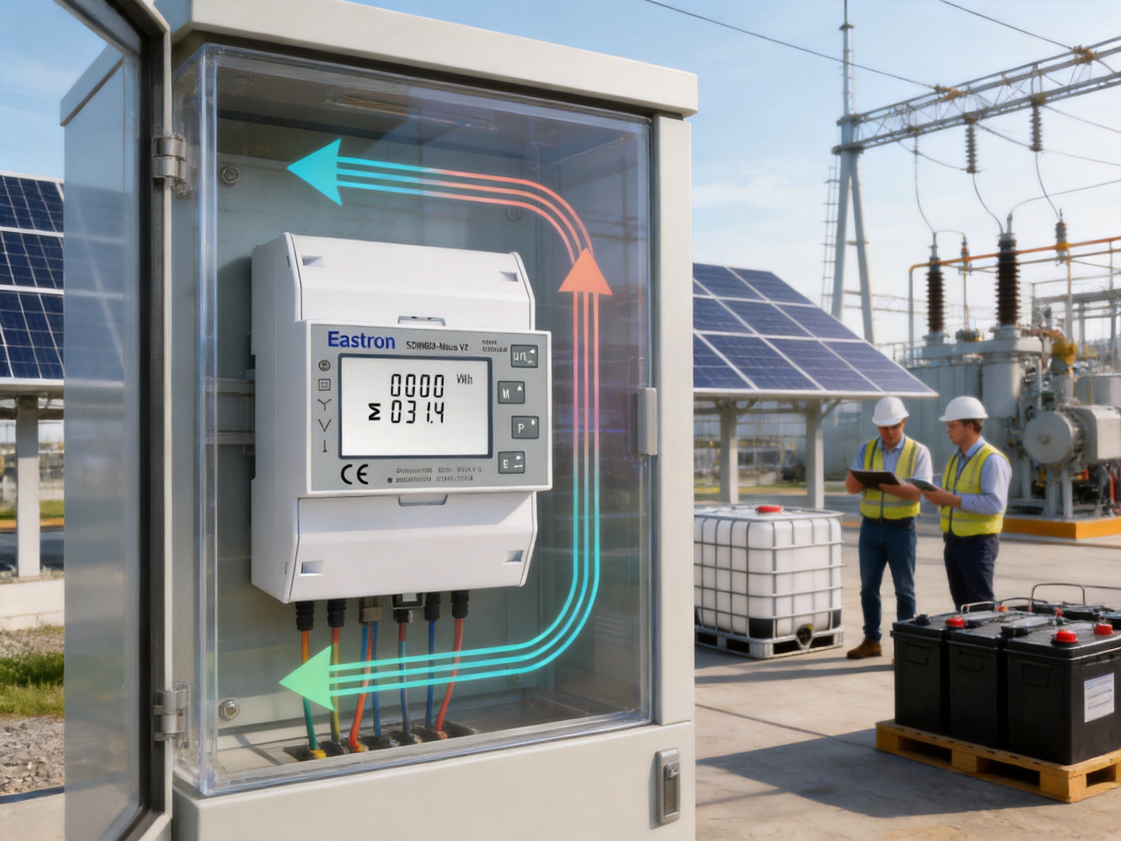
Accurate electricity measurement is now a core requirement for commercial buildings, industrial facilities, renewable-energy installations, infrastructure projects, and multi-tenant properties. Energy users need more than a simple consumption display. They require dependable measurement, flexible electrical compatibility, transparent billing data, communication with supervisory systems, and a compact device that can be installed without unnecessary wiring or external components.
The 100A M-Bus DIN-rail three-phase MID energy meter is designed to meet these requirements in one integrated instrument. The SDM630-MB model combines direct current measurement up to 100A, support for several wiring configurations, active and reactive energy measurement, bidirectional import and export monitoring, pulse outputs, and M-Bus EN13757 communication. Its four-module, 72 mm DIN-rail housing allows it to fit into compact distribution boards while retaining a broad set of measurement and communication functions.
In addition to its technical capabilities, the meter is supported by the manufacturing, testing, research, and quality-control resources of Eastron Electronic Co., Ltd. The company develops electricity meters, power analyzers, current sensors, communication modules, and energy-management products for international markets. Its own professional laboratory supports electromagnetic compatibility, low-voltage, accuracy, and environmental testing according to relevant IEC, EN, GB, and UL requirements.
This article examines the meter’s functions, electrical performance, communications, installation benefits, application value, manufacturing strengths, and advantages compared with less integrated energy-metering alternatives.
A three-phase energy meter measures electrical parameters across three conductors and, where applicable, a neutral conductor. Three-phase systems are widely used in commercial buildings, factories, workshops, data centers, charging infrastructure, pumping stations, HVAC systems, and distributed-energy installations because they deliver power efficiently and support balanced or unbalanced loads.
A basic meter may record only accumulated kilowatt-hours. That information is useful, but it does not fully explain how a system is operating. Facility managers may also need to know the voltage on each phase, current loading, active power, reactive power, apparent power, power factor, frequency, harmonic distortion, and maximum demand. A multifunction energy meter brings these values together in a single device.
The SDM630-MB extends this measurement capability with communication and pulse outputs. It can therefore serve as both a local display instrument and a data source for a building-management system, energy-management platform, data logger, gateway, or metering network. This combination helps users move from occasional manual readings to continuous energy observation and analysis.
Another important requirement is compatibility. Electrical systems do not all use the same connection arrangement. A device that supports only one configuration may require a different model for each project. The SDM630-MB can work with 3P4W, 3P3W, and 1P2W systems, providing greater flexibility for distributors, panel builders, electrical contractors, and system integrators.
The SDM630-MB is a three-phase multifunction energy meter intended for direct connection in systems with a maximum current of 100A. It is installed on a standard DIN rail and occupies four modules, or approximately 72 mm of panel width. The unit is identified as a 100A M-Bus DIN-rail three-phase MID energy meter and is designed for applications requiring measurement, local indication, pulse output, and M-Bus EN13757 communication.
The meter can measure and display the characteristics of single-phase two-wire, three-phase three-wire, and three-phase four-wire supplies. It supports measurements associated with imported and exported energy, allowing it to monitor power flowing in both directions. This is particularly useful in systems that include photovoltaic generation, battery storage, regenerative equipment, or other sources that can send power back toward the grid.
Its multifunction design includes measurements of kilowatt-hours, kilovolt-ampere reactive hours, watts, volt-amperes reactive, volt-amperes, volts, amperes, power factor, total harmonic distortion, frequency, and demand values. The range of available information allows users to evaluate not only how much energy has been used but also how efficiently and reliably the electrical system is operating.
The meter includes two pulse outputs for energy-related signaling. Depending on the configuration and connected monitoring equipment, pulse outputs can be used for imported and exported energy indications or for connection to a pulse counter, building-management controller, data acquisition unit, or remote display.
Its primary digital communication interface is M-Bus according to EN13757. M-Bus is widely used for utility and submetering applications because it is designed for communicating meter data over a bus network. It allows multiple meters to be connected to a central master device, reducing the need for individual point-to-point wiring to every meter.
| Item | Specification or Function |
|---|---|
| Meter type | Three-phase multifunction MID energy meter |
| Maximum direct current | 100A |
| Supported systems | 3P4W, 3P3W, and 1P2W |
| Rated voltage | 230V line-neutral or 120V line-neutral |
| Housing | DIN-rail mounting, four modules, approximately 72 mm wide |
| Energy measurement | Active and reactive energy, including bidirectional measurement |
| Outputs | Two pulse outputs |
| Communication | M-Bus EN13757-3 |
| Display and measurement | Voltage, current, power, energy, power factor, THD, frequency, demand, and related values |
| Certification information | Assessed and certified as meeting the requirements of EU Directive 2014/32/EU, according to the supplied product information |
One of the most important advantages of this meter is its ability to connect directly to loads up to 100A. Many higher-current meters require external current transformers. Current transformers can be useful in large installations, but they also increase the number of components, extend installation time, occupy additional panel space, and introduce possible ratio, polarity, and wiring errors.
For circuits within the meter’s direct-load range, direct connection can simplify the complete metering arrangement. The installer does not need to select, mount, and separately wire a current transformer for each phase. The panel layout can be more compact, and the bill of materials can be reduced. This is especially valuable in submetering cabinets, apartment distribution boards, small commercial installations, workshops, and energy-monitoring panels where space and cost are tightly controlled.
Eliminating external CTs also makes commissioning more straightforward. A current transformer system requires careful attention to primary and secondary ratings, phase association, direction, burden, and terminal security. A direct-connected meter avoids many of these additional considerations. The installer still needs to follow the applicable electrical codes, isolation procedures, terminal requirements, and manufacturer instructions, but the metering chain is less complicated.
The rated current is specified as 10A, with a maximum current of 100A, a minimum current of 0.3A, and a starting current of 40mA. These values define the operating range and help users select the meter for an appropriate circuit. The maximum current should not be treated as a target operating value without considering conductor size, protection, ambient temperature, enclosure conditions, and local regulations.
Compared with a CT-operated meter, a direct 100A meter can offer fewer components between the load and the measurement electronics. That may reduce installation complexity and provide a cleaner panel design. It can also be more convenient for contractors who need to install a large number of submeters in a limited time.
Direct connection is not universally superior. High-current industrial feeders may exceed 100A, and CT measurement remains appropriate for those applications. However, for circuits that fit within the direct-load rating, the integrated approach offers an effective balance between measurement capability, installation simplicity, and cost control.
Electrical projects may use different wiring arrangements depending on the supply architecture, equipment type, national practice, and distribution design. Three-phase four-wire systems provide three phase conductors and a neutral. Three-phase three-wire systems omit the neutral and are commonly associated with certain industrial loads and balanced systems. Single-phase two-wire systems are used for individual circuits and smaller loads.
Supporting 3P4W, 3P3W, and 1P2W configurations gives the meter a wider application range than a model designed for only one connection method. It can be deployed across mixed projects without requiring a completely different instrument for each circuit type. This helps distributors simplify inventory and allows system designers to standardize their metering architecture.
In a three-phase four-wire installation, the meter can evaluate phase-to-neutral voltage, phase current, power, and energy. In a three-phase three-wire installation, the measurement method is adapted to the absence of a neutral conductor. In a single-phase two-wire application, the device can be used for individual-circuit monitoring where the installation design and configuration are suitable.
Correct programming and wiring are essential. The supported wiring modes do not mean that every arrangement can be connected interchangeably. The installer must identify the supply system, confirm terminal assignments, select the proper wiring setting, and verify the phase sequence and polarity. A commissioning check should compare the displayed values with expected voltage, current, load direction, and energy behavior.
Energy data becomes more useful when it is combined with electrical-quality and loading information. The SDM630-MB provides a broad measurement set that can help operators understand the performance of connected equipment and distribution systems.
Voltage measurement can reveal supply stability, phase imbalance, undervoltage, or overvoltage conditions. Current measurement indicates loading on individual phases and can expose overload risks or poor load distribution. The stated measurement accuracy is ±0.5% for voltage and ±0.5% for current, subject to the specified operating conditions and installation requirements.
Monitoring voltage and current together also helps users calculate whether equipment is operating within an expected range. A current increase without a corresponding production increase may indicate mechanical problems, process changes, or inefficient equipment. A voltage deviation accompanied by unusual current behavior may suggest a supply-side issue.
Active power, measured in watts, represents the power converted into useful work, heat, light, or mechanical output. Reactive power, measured in volt-amperes reactive, is associated with magnetic and electric fields in inductive and capacitive equipment. Apparent power, measured in volt-amperes, represents the combined electrical demand on the supply.
The meter specifies ±1% accuracy for active power, reactive power, and apparent power. These measurements can support load studies, equipment comparisons, demand management, and power-factor improvement projects. They can also help users distinguish between a real increase in energy consumption and a change in reactive loading that affects the capacity required from the electrical network.
Power factor indicates the relationship between active power and apparent power. A low power factor may cause higher current for the same useful power, increasing losses and consuming more capacity in cables, transformers, and switchgear. The meter provides power-factor measurement with a stated accuracy of ±0.01.
Continuous power-factor monitoring is useful in factories with motors, welding equipment, compressors, pumps, and variable-speed drives. It can help identify when compensation equipment is needed or when existing correction equipment is not operating as expected.
Frequency measurement provides information about the stability of the AC supply. The stated frequency accuracy is ±0.2%. Total harmonic distortion measurement provides an additional view of waveform quality. Harmonics can be introduced by power electronics, switching supplies, variable-frequency drives, inverters, and other nonlinear loads.
THD data does not replace a complete power-quality investigation, but it can act as an important monitoring indicator. If distortion rises over time, the facility operator may investigate possible effects on transformers, neutral conductors, capacitors, motors, control equipment, and communication systems.
Maximum demand is an important factor in many commercial and industrial energy programs. A facility may consume a moderate amount of energy over a month but still create a high short-term demand peak. Some utility tariffs and internal allocation systems use demand values in addition to total energy consumption.
The meter can measure maximum demand current over preset periods of up to 60 minutes, according to the supplied product information. Demand monitoring can help facility managers identify peak-producing equipment, schedule nonessential loads, and evaluate whether operational changes reduce demand charges.
Traditional energy meters often focus on energy imported from the utility. Modern electrical systems increasingly include photovoltaic arrays, battery storage, combined heat and power units, regenerative drives, and other distributed sources. In such systems, energy may flow in both directions.
The SDM630-MB supports bidirectional measurement. It can distinguish imported and exported active energy, making it suitable for applications where a site both consumes and produces electrical power. This capability is important for monitoring self-consumption, surplus generation, export levels, and the relationship between on-site generation and grid demand.
Bidirectional measurement also benefits industrial equipment that returns energy during braking or deceleration. A complete energy profile can show not only consumption but also the amount of energy sent back into the upstream network.
When used for billing or formal allocation, the meter must be installed, configured, sealed, and verified according to the applicable legal and project requirements. The product information states that the meter has been assessed and certified as meeting the requirements of EU Directive 2014/32/EU. Project engineers should confirm the exact certification scope, marking requirements, installation conditions, and local acceptance procedures before using any meter for regulated billing.
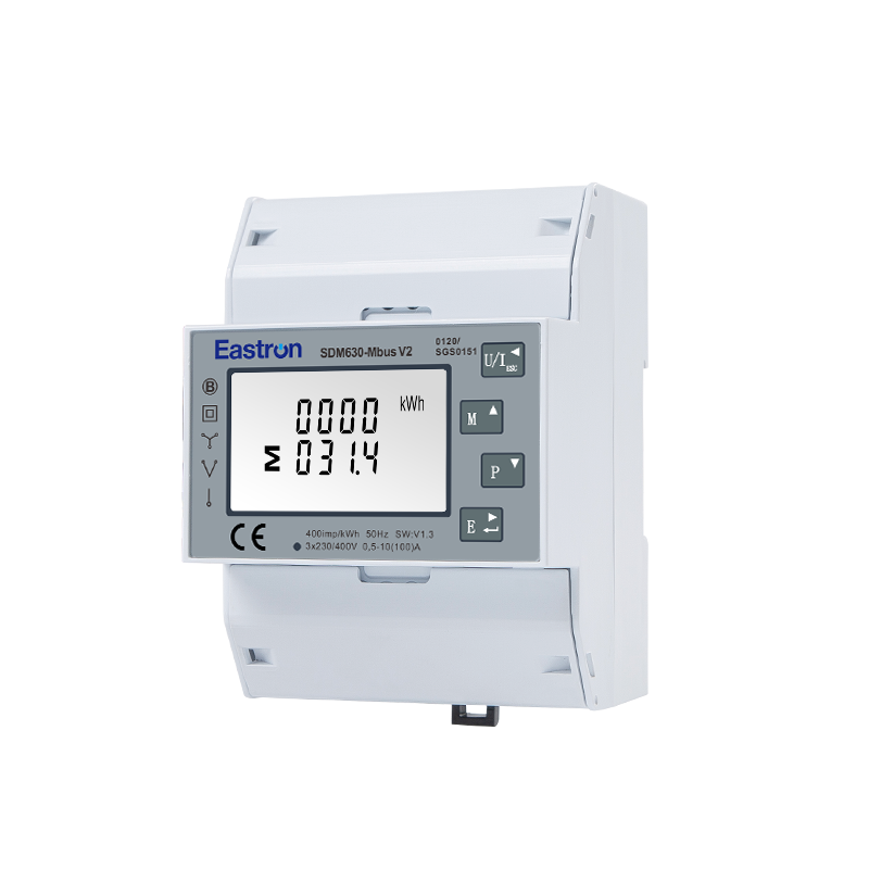
100A M-bus EN13757 Din Rail Three Phase MID Energy Meter
M-Bus, or Meter-Bus, is a communication system developed for reading and managing utility meters. The SDM630-MB uses M-Bus EN13757-3 communication, allowing measurement information to be transmitted to a compatible master, concentrator, gateway, or building-management system.
A major benefit of M-Bus is its suitability for multi-meter networks. In a building with many tenant meters, a central M-Bus master can collect data from multiple devices over a shared communication structure. This is more efficient than manually reading each display and can simplify the design of a centralized energy-monitoring system.
The stated M-Bus communication address range is 1 to 250. The maximum transmission distance is listed as 1000 meters, while the available baud rates range from 600 to 9600 bps. Parity can be set to none, odd, or even, and stop bits can be configured as one or two. The final network performance depends on cable type, topology, master capability, power budget, electromagnetic conditions, termination practices, and the number of connected devices.
For larger sites, M-Bus data can be routed through a gateway to an Ethernet, cellular, cloud, or other supervisory system. This creates a path from the meter installed in a distribution board to a dashboard used by an energy manager or facility operator.
M-Bus communication supports a structured approach to tenant billing, departmental energy allocation, equipment monitoring, and performance reporting. A building operator can assign meters to floors, rooms, production lines, or tenants and retrieve consistent readings at scheduled intervals.
Automated data collection reduces transcription errors and minimizes the need for staff to enter electrical rooms for routine readings. It also makes it easier to compare consumption across time periods. Daily, weekly, and monthly trends can reveal seasonal changes, abnormal nighttime loads, process inefficiencies, or unexpected consumption increases.
Communication also improves maintenance visibility. A supervisory system can identify a meter that stops responding, reports an unexpected value, or shows a sudden change in load. Although the meter is not a complete fault-diagnostic system, its data can provide an early indication that further inspection is needed.
In addition to M-Bus, the meter provides two pulse outputs. Pulse outputs are a simple and widely understood method of communicating accumulated energy. A pulse counter or controller can use the output to calculate energy based on the configured pulse constant.
Pulse interfaces are useful when a project already has a pulse-based data-acquisition system or when the user wants a basic energy signal without implementing a complete digital communication network. They can also be connected to display panels, programmable logic controllers, remote input modules, or legacy building-management equipment where appropriate.
The two outputs allow separate signaling for imported and exported energy in applications that require directional information. The exact wiring, pulse constant, voltage level, isolation, and receiving-device requirements must be checked against the product documentation and the receiving equipment specifications.
The combination of M-Bus and pulse outputs is an advantage over meters that provide only a local display. It gives the user multiple paths for system integration and permits the device to be used in both new and existing monitoring infrastructures.
Panel space is increasingly valuable. Electrical distribution boards often need to accommodate circuit breakers, residual-current devices, contactors, surge protection, control relays, gateways, and other automation components. A four-module, 72 mm-wide meter provides substantial measurement functionality without occupying the space of a larger panel instrument.
DIN-rail mounting makes the meter convenient for modular assemblies. It can be installed alongside protective and switching devices in a dedicated metering section or integrated into a control cabinet. The format is familiar to electrical contractors and supports efficient assembly in standard enclosures.
The compact form factor is particularly beneficial in retrofit work. Existing panels may have limited spare space, and adding external current transformers or a large multifunction instrument may require extensive modification. A direct-connected DIN-rail meter can often be incorporated with less disruption, provided the electrical ratings and safety clearances are suitable.
Compact size does not eliminate the need for thermal planning. The panel designer should consider the surrounding devices, conductor heating, ventilation, operating temperature, and enclosure rating. Proper labeling and access for inspection should also be maintained.
Measurement accuracy is fundamental when energy data is used for cost allocation, efficiency analysis, equipment verification, or contractual settlement. The supplied specifications identify active-energy accuracy as Class 1/0.5 under IEC 62053-21 and Class B/C under EN50470-3:2022. Reactive energy is listed as Class 2 under IEC 62053-23.
The terminology and applicable class depend on the relevant standard, product version, test conditions, and certification scope. Users should therefore select the required accuracy class according to the project’s legal and technical requirements rather than relying only on general marketing descriptions.
The stated measurement accuracies for voltage, current, frequency, power factor, active power, reactive power, and apparent power provide useful reference points during product selection. However, accuracy in the field depends on correct wiring, stable supply conditions, conductor arrangement, load level, frequency, temperature, electromagnetic environment, and compliance with installation instructions.
For commissioning, the installer should verify phase sequence, voltage readings, current direction, energy accumulation, communication address, pulse behavior, and any programmed system parameters. Where the meter is used in a regulated metering application, formal verification and sealing procedures should be completed by qualified personnel.
The performance of an energy meter depends not only on its circuit design but also on the quality of its manufacturing process. Measurement products must maintain stable characteristics across production batches, operating temperatures, supply variations, and long service periods. A manufacturer with dedicated development, testing, and quality systems is better positioned to control these factors.
Eastron Electronic Co., Ltd. is headquartered in Jiaxing, Zhejiang, China, near major commercial and industrial centers including Shanghai and Hangzhou. The company develops and produces electricity meters, power analyzers, current sensors, communication modules, and energy-management systems. Its product range supports applications from basic electricity measurement to connected energy-management solutions.
The company has development teams in China and the United Kingdom and cooperates with universities and research institutions. This combination of engineering resources helps support product development in embedded software, communication, measurement algorithms, hardware design, and application-specific energy monitoring.
A significant manufacturing advantage is the company’s professional laboratory. According to the supplied company information, the laboratory is capable of performing EMC, LVD, accuracy, and environmental tests according to IEC, EN, GB, and UL standards.
EMC testing evaluates the meter’s ability to operate correctly in the presence of electromagnetic interference and its tendency to emit interference that could affect other equipment. This is important in industrial panels containing contactors, variable-frequency drives, switching power supplies, and communication devices.
Low-voltage testing examines safety-related characteristics associated with electrical insulation, dielectric strength, leakage, and other relevant conditions. Accuracy testing verifies measurement performance under defined voltage, current, frequency, power-factor, and environmental conditions. Environmental testing can evaluate behavior under temperature, humidity, vibration, and other stresses relevant to the intended application.
Testing during development and production helps identify weaknesses before products reach the field. It also supports more consistent manufacturing by providing controlled methods for evaluating components, assemblies, and finished instruments.
The company follows an ISO 9001 quality-management system, according to the supplied information. A quality-management system provides a structured framework for design control, purchasing, production, inspection, documentation, corrective action, and customer support.
The company’s production is also described as being approved by SGS according to MID standards. In regulated energy-metering applications, control of documentation, traceability, calibration, testing, and production consistency is especially important. The stated assessment and certification related to EU Directive 2014/32/EU further supports the product’s suitability for projects that require compliant measurement equipment, subject to the exact certificate and application conditions.
Patented technologies in software, embedded software, and hardware provide another foundation for product development. Metering products increasingly depend on firmware for measurement processing, display management, communication, tariff handling, demand calculation, and configuration security. Control of both hardware and embedded software can help a manufacturer optimize the interaction between measurement circuits and user functions.
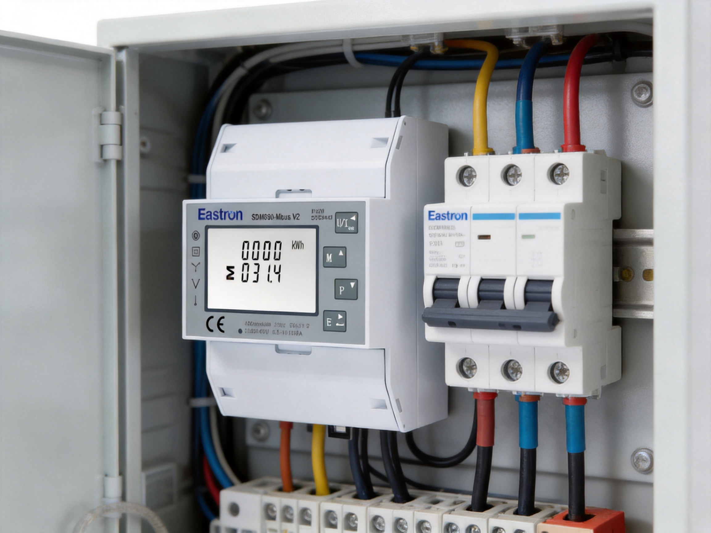
The meter’s electronic parameters can be configured using its buttons, and the supplied information states that configuration is password protected. Local configuration is useful during installation because it allows the installer to set the wiring mode, communication parameters, address, and other available values without requiring a separate programming tool for every adjustment.
Password protection helps reduce the possibility of unauthorized changes. In a metering system, an incorrect wiring mode or communication address can lead to inaccurate readings, communication conflicts, or loss of data. Protecting configuration settings is therefore an important operational feature.
Good commissioning practice should include recording the configured address, wiring type, date of installation, meter identification, pulse settings, and any tariff or demand settings. The password should be managed according to the organization’s security procedures. Where the meter is connected to a larger network, access to the M-Bus master and gateway should also be controlled.
Commercial properties often need to allocate energy costs among tenants, departments, retail units, offices, or shared services. A compact three-phase meter can be installed in distribution boards serving individual areas or major loads.
For example, a building may use separate meters for air-conditioning systems, elevators, lighting panels, data rooms, kitchens, and tenant spaces. M-Bus communication can collect readings from all meters and forward them to a central platform. This supports transparent reporting and helps property managers identify areas with unusual consumption.
In office buildings, the meter can monitor floor-level distribution, server-room demand, or mechanical services. In retail properties, it can support tenant submetering and display energy trends. In schools, hospitals, and public buildings, it can help compare energy use across zones and identify opportunities for efficiency improvements.
Industrial sites often contain a mixture of motors, heaters, compressors, pumps, conveyors, machine tools, welding systems, and electronic drives. These loads can vary significantly throughout the day and may create high demand or power-quality concerns.
The meter’s measurements of active power, reactive power, apparent power, power factor, frequency, and THD can provide valuable information for production and maintenance teams. A meter installed at a production line can show how much energy is consumed per shift or per batch. A meter at a compressor station can help identify leaks or inefficient operating schedules. A meter at a motor control center can reveal phase loading and demand behavior.
Because the device supports direct measurement up to 100A, it is especially suitable for many individual machines and subcircuits. Larger feeders can use appropriately selected CT-operated equipment, while smaller branch circuits can use direct-connected meters to create a layered monitoring architecture.
Renewable-energy systems require a clear understanding of power direction. A solar installation may supply local loads during daylight, export surplus electricity at other times, and import energy from the grid when generation is insufficient. Battery systems add further charging and discharging cycles.
Bidirectional measurement allows the operator to observe these energy flows. The meter can be used at a distribution point to monitor imported energy, exported energy, and the overall relationship between generation and consumption. M-Bus communication can send these values to a supervisory controller or energy-management platform.
For a solar installer or energy consultant, the data can support self-consumption analysis, inverter performance checks, export limitation strategies, and comparisons between expected and actual site behavior. The meter does not replace inverter monitoring or protection equipment, but it provides an independent electrical measurement point that can improve system visibility.
The market includes simple single-function meters, meters requiring external CTs, meters with limited wiring compatibility, and multifunction devices using different communication protocols. The SDM630-MB has several advantages when its features are compared with these alternatives.
A basic kWh meter may show accumulated active energy but provide little information about voltage quality, current loading, power factor, reactive power, demand, or harmonics. The multifunction design of the SDM630-MB gives users a broader operational picture without adding separate instruments for each parameter.
This can reduce panel complexity and improve the value of collected data. When a facility experiences higher energy use, operators can investigate whether the cause is increased active load, poor power factor, phase imbalance, harmonic distortion, or a change in operating schedule.
For circuits below 100A, direct connection avoids the extra cost and space requirements associated with external current transformers. It also reduces the number of wiring points and eliminates the need to match CT ratios to the meter. This can simplify installation and lower the risk of polarity or ratio errors.
Support for 3P4W, 3P3W, and 1P2W systems gives the meter broader project coverage. A distributor may be able to use one product family across multiple supply arrangements instead of stocking separate models for each configuration.
A local-display-only meter requires manual readings or additional conversion equipment. The integrated M-Bus interface allows the SDM630-MB to participate in a centralized metering network. This improves data collection, supports automation, and reduces the labor associated with routine inspections.
As distributed generation expands, a meter that records only imported energy may not provide a complete picture. Bidirectional measurement is more suitable for sites with solar generation, storage, regenerative equipment, or export activity.
A larger panel meter may provide similar measurement functions but occupy more space and require a different mounting arrangement. The four-module DIN-rail housing is advantageous where panel density, standardization, and fast assembly are important.
These advantages do not mean that one meter is suitable for every application. Projects exceeding 100A, requiring specialized power-quality analysis, using unusual voltage systems, or demanding a different communications protocol may need another product. The correct comparison should always consider the full technical and regulatory requirements.
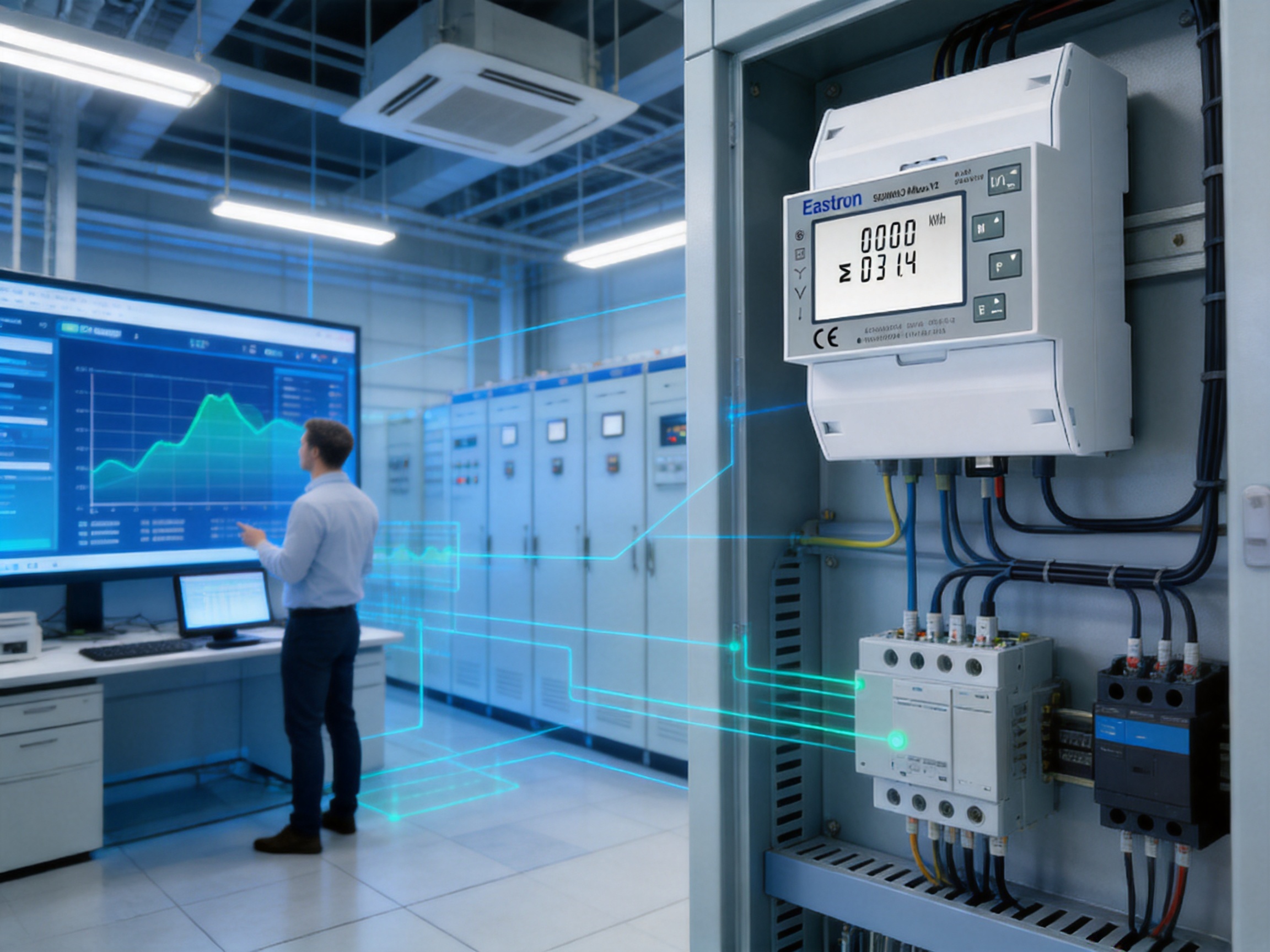
Installation should be completed by qualified electrical personnel using the wiring diagram and technical documentation supplied for the exact model. Before work begins, the circuit must be isolated and verified as de-energized. Appropriate protective equipment, conductor sizing, overcurrent protection, terminal tightening, enclosure requirements, and local electrical rules must be observed.
The installer should first identify the system type. The meter can be used with 3P4W, 3P3W, and 1P2W configurations, but the correct mode must be selected. The rated voltage is specified as 230V line-neutral or 120V line-neutral, and the operational voltage range is listed as 80% to 120% of the rated voltage. The actual installation must remain within the applicable limits.
After wiring, the installer should check that each phase conductor is connected to the correct terminal and that current direction corresponds to the intended import and export readings. A reversed phase or incorrect conductor association may produce unexpected power direction or inaccurate phase information.
The communication network should be checked separately. Each meter must have a unique address within the M-Bus network. The master device should be compatible with the configured baud rate, parity, stop bits, and addressing method. Cable routing should avoid unnecessary exposure to strong electromagnetic fields, and the network should be tested before the panel is closed.
Commissioning should include a functional test at a known or expected load. The voltage readings should be compared with a calibrated reference where appropriate. Current should be checked against the connected load. Active power should respond logically when equipment is switched on or off. Energy registers should increase in the expected direction, and pulse outputs should be verified by the receiving system.
Installing a meter is only the first step. The greatest benefit comes from converting its measurements into useful operational actions. A building-management or energy-management system can collect M-Bus data at regular intervals and organize it by site, panel, tenant, department, or equipment group.
Trend data can reveal baseload consumption during unoccupied hours. It can show whether a production line consumes energy while idle, whether HVAC equipment operates outside scheduled periods, or whether a refrigeration system is cycling abnormally. Comparisons between similar areas can identify inefficient equipment or unusual operating patterns.
Power-factor information can support decisions about capacitor banks or other correction measures. Demand data can help schedule high-power loads. THD readings can indicate when a more detailed power-quality assessment is needed. Voltage and current trends can support preventive maintenance by showing gradual changes before a failure occurs.
For organizations pursuing energy-management goals, the meter can provide repeatable measurements for baseline development, improvement verification, and internal reporting. It can also support sustainability programs by separating consumption among different processes and identifying where efficiency investments will have the greatest effect.
Before selecting the meter, the user should confirm the electrical system, voltage, current, frequency, load direction, installation space, communication architecture, and legal metering requirements. The maximum direct current of 100A makes the product appropriate for many distribution and submetering applications, but larger circuits require a properly rated alternative.
The user should also determine whether M-Bus is the preferred communication protocol. M-Bus is highly suitable for utility-metering networks, while some automation systems may primarily use RS485 Modbus, Ethernet, BACnet, or another protocol. The product family includes other configurations with different outputs and interfaces, but the SDM630-MB specifically provides two pulse outputs and M-Bus EN13757 communication.
If the installation requires two tariffs, a digital input, or RS485 Modbus, the corresponding model must be selected rather than assuming that all functions are included in every version. Product codes should be confirmed before ordering because similar model names may represent different interfaces or options.
For formal billing, the project engineer should review the applicable certificate, accuracy class, sealing provisions, verification procedure, and local authority requirements. The existence of MID-related certification information is valuable, but compliance must be matched to the specific intended use and jurisdiction.
Eastron Electronic Co., Ltd. has developed a product portfolio covering electricity meters, smart meters, power analyzers, current sensors, communication modules, and energy-management solutions. This breadth allows customers to source complementary products from a company with experience across several areas of energy measurement.
The company serves customers in Europe, Asia-Pacific, America, the Middle East, and Africa, according to the supplied company profile. International experience can be useful when projects involve different standards, communication requirements, electrical practices, and documentation expectations.
Its stated mission is to create value for customers and grow together with partners. In practical terms, product value includes not only the meter itself but also technical documentation, configuration assistance, application support, production consistency, and after-sales service. For distributors and system integrators, these factors can influence total project cost and deployment time as much as the purchase price.
The company’s research and development activities in China and the United Kingdom, cooperation with universities, professional laboratory, patents, quality-management system, and MID-related production approval form a technical foundation for continued product development. These strengths are relevant to customers who require a stable supplier rather than a single isolated device.
Routine maintenance for a digital DIN-rail meter generally focuses on visual inspection, terminal condition, enclosure temperature, communication status, and verification of displayed values. The enclosure should remain clean and dry, and the meter should be protected from conditions outside its specified environmental range.
Operators should look for loose terminals, discoloration, unusual heating, damaged conductors, condensation, or signs of electrical stress. Any inspection must follow safe isolation procedures. Communication logs can also be reviewed for repeated timeouts or missing data.
Where measurement accuracy is critical, periodic verification may be included in the facility’s maintenance plan. The appropriate interval depends on regulations, application risk, environmental conditions, internal quality procedures, and the consequences of inaccurate readings.
Firmware, communication settings, and configuration records should be managed carefully. Unauthorized changes can affect data interpretation, so access control and documentation are important. If a meter is replaced, the new device should be assigned an appropriate network address and its register mapping should be checked before normal operation resumes.
The SDM630-MB is a three-phase multifunction energy meter for DIN-rail installation. It supports direct measurement up to 100A and includes two pulse outputs and M-Bus EN13757-3 communication.
Yes. The product information specifies bidirectional measurement, allowing the meter to monitor energy flowing into a site and energy exported from a site. This is useful for photovoltaic, storage, regenerative, and other distributed-energy applications.
For circuits within its direct-load rating, the meter can connect directly to currents up to 100A, so external current transformers are not required. Circuits above the rating need a different measurement arrangement and a suitably rated product.
The meter supports three-phase four-wire, three-phase three-wire, and single-phase two-wire systems. The correct wiring mode must be selected and the meter must be connected according to the applicable wiring diagram.
The rated voltage is specified as 230V line-neutral or 120V line-neutral. The operational voltage range is listed as 80% to 120% of the rated voltage. The project engineer should verify compatibility with the actual supply.
Available measurements include active energy, reactive energy, active power, reactive power, apparent power, voltage, current, power factor, total harmonic distortion, frequency, maximum demand, and related electrical parameters.
M-Bus is used to transmit meter data to a compatible master, concentrator, gateway, or energy-management system. It is particularly useful when several utility or submetering devices need to communicate with a central system.
The supplied specifications list an address range of 1 to 250, a maximum transmission distance of 1000 meters, and baud rates from 600 to 9600 bps. Actual network performance depends on the complete installation, cable, master, topology, and environmental conditions.
The two pulse outputs can provide energy-related pulse signals to a pulse counter, controller, data logger, or other compatible receiving device. They may be used for imported and exported energy indications, depending on configuration and application requirements.
The supplied information states that the meter has been assessed and certified as meeting the requirements of EU Directive 2014/32/EU and lists active-energy accuracy classes under IEC and EN standards. However, suitability for a particular billing application must be confirmed against the exact certificate, installation rules, national regulations, and project requirements.
The unit occupies four DIN modules and is approximately 72 mm wide. This compact format is suitable for many modular distribution boards and control cabinets.
Yes. The supplied information states that electronic parameters can be set using the buttons and that configuration is password protected. Installers should document all settings during commissioning.
It combines direct 100A measurement, several wiring modes, multifunction electrical measurement, bidirectional energy monitoring, two pulse outputs, M-Bus communication, and a compact DIN-rail design. A basic meter may provide only accumulated active energy and a local display.
The manufacturer has research and development teams, a professional laboratory for EMC, low-voltage, accuracy, and environmental testing, an ISO 9001 quality-management system, patented hardware and software technologies, and production approval associated with MID standards, according to the supplied company information.
No. The stated maximum direct current is 100A. Circuits above this value require a different meter or a current-transformer-based measurement solution with appropriate ratings.
The 100A M-Bus DIN-rail three-phase MID energy meter provides a practical combination of measurement depth, installation flexibility, communication capability, and compact construction. Its direct connection up to 100A can reduce the need for external current transformers on suitable circuits. Support for 3P4W, 3P3W, and 1P2W systems expands its application range, while bidirectional measurement makes it relevant to modern sites with renewable generation, storage, or regenerative loads.
Its multifunction measurements go beyond simple energy accumulation. Voltage, current, active power, reactive power, apparent power, power factor, frequency, THD, and demand information can help users understand system behavior and make better decisions about efficiency, maintenance, capacity, and operating schedules.
M-Bus EN13757-3 communication and two pulse outputs allow the meter to serve both modern networked systems and simpler pulse-based installations. The four-module DIN-rail housing supports efficient panel assembly, and password-protected local configuration helps preserve the integrity of operating parameters.
The product is further supported by the manufacturer’s development resources, professional laboratory, testing capabilities, quality-management system, international experience, and focus on electricity measurement technologies. For commercial, industrial, renewable-energy, and submetering projects that require an integrated 100A three-phase solution, the SDM630-MB offers a balanced alternative to basic meters, CT-dependent devices, and instruments with limited communications or wiring compatibility.
IEC 62053-21, Electricity Metering Equipment — Particular Requirements — Static Meters for AC Active Energy.
IEC 62053-23, Electricity Metering Equipment — Particular Requirements — Static Meters for Reactive Energy.
EN 50470-3:2022, Electricity Metering Equipment — Particular Requirements — Static Meters for Active Energy.
EN 13757-3, Communication Systems for Meters and Remote Reading of Meters — Application Layer.
EU Directive 2014/32/EU on the Harmonisation of the Laws of Member States Relating to the Making Available on the Market of Measuring Instruments.
SDM630-MB Product Technical Information and Electrical Specifications.
Manufacturer Information on Electricity Measurement Products, Research and Development, Laboratory Testing, Quality Management, and MID-Related Production.
Your email address will not be published. Required fields are marked *

We develop and produce high performance electricity meters, power analyzers, current sensors, communication modules and management systems.
Address:NO. 52, Dongjin Road, Nanhu, Jiaxing, Zhejiang, China
Copyright @ Eastron Electronic Co., Ltd. All rights reserved
