

 English
 Español
 Deutsch
 中文简体


Product Consultation
Your email address will not be published. Required fields are marked *
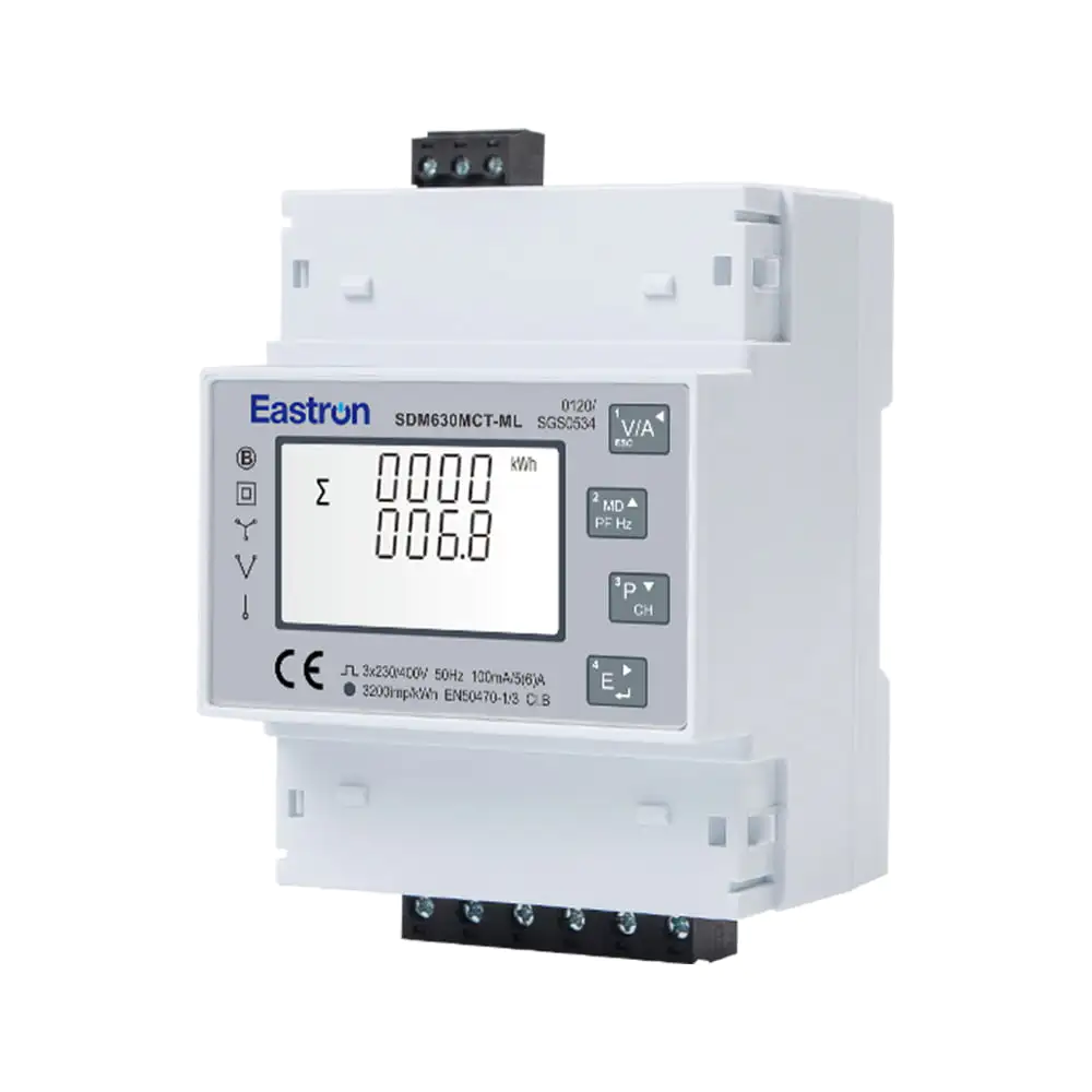
Quad Load Three Phase Multi-function RS485 Energy Meter for Data Center Metering
Aug 03,2022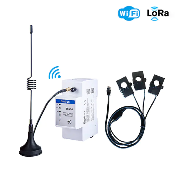
Wifi & LoRa Three Phase Din Rail Energy Meter for PV Metering
Sep 19,2025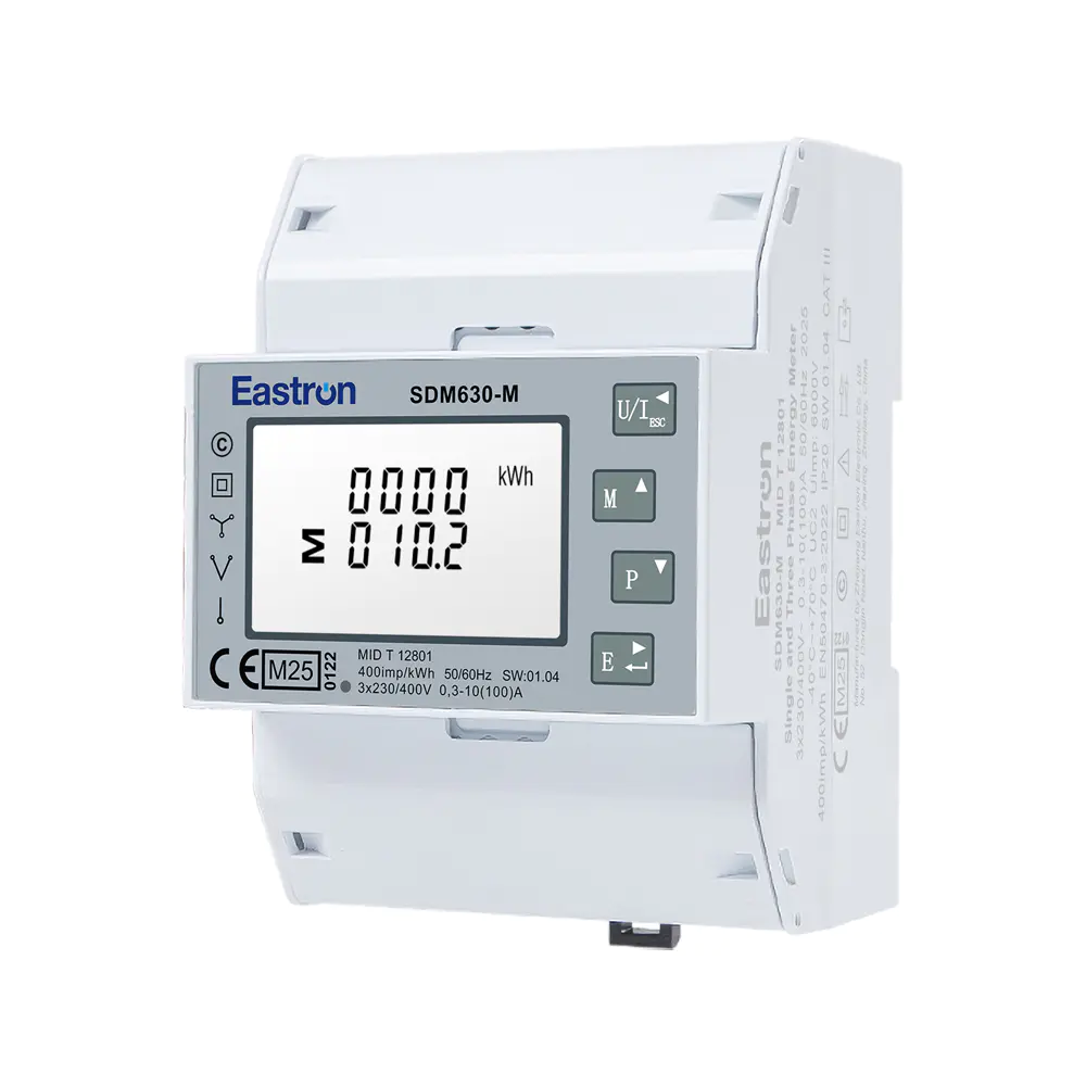
MID UL Certified Din Rail Three Phase Multi-function Energy Meter for EV Charging Metering
Aug 02,2022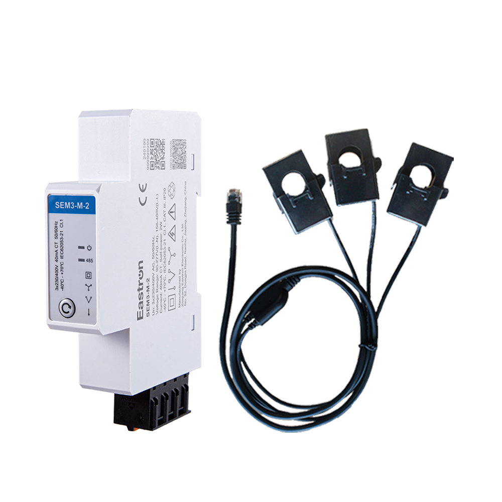
RS485 CT Connection Three Phase Din Rail Energy Meter for PV Metering
May 30,2025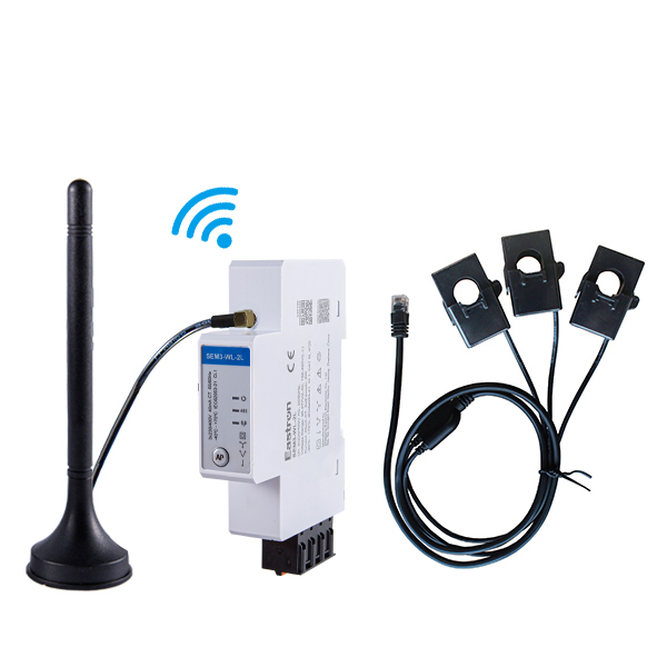
CT Type Three Phase Din Rail Wifi Energy Meter for PV Metering
May 30,2025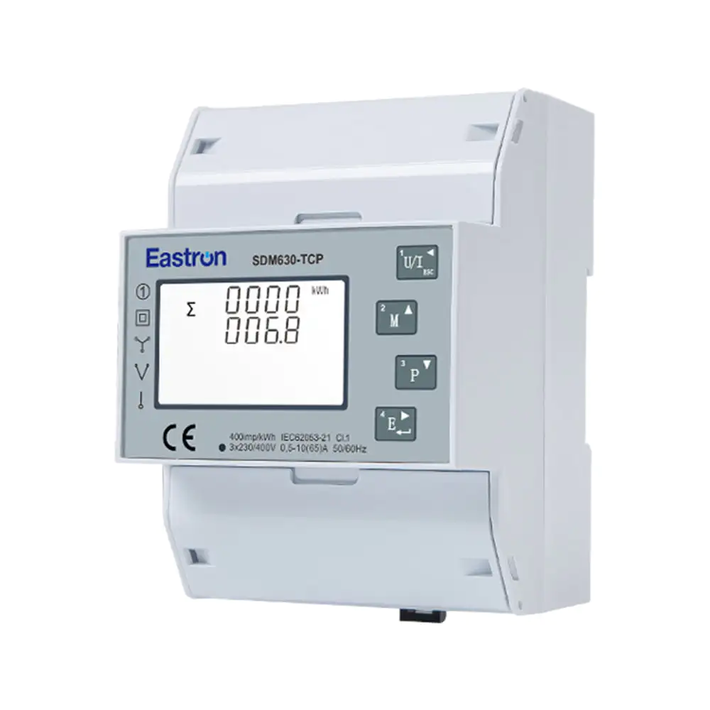
Direct Type Three Phase Ethernet Modbus TCP Energy Meter for Data Center Metering
Nov 24,2022Content
Reliable electrical measurement is becoming increasingly important as buildings, factories, photovoltaic installations, charging infrastructure, and distributed energy systems become more complex. Operators need more than a simple indication of voltage or current. They need accurate measurements, flexible communication, compact installation, dependable data transmission, and the ability to understand energy flow in real time.
The CT-operated Wi-Fi, Ethernet, and RS485 three-phase multifunction energy meter is designed for this environment. The SEM5-5 combines current-transformer measurement, multi-parameter electrical monitoring, wired and wireless communication, energy direction analysis, and DIN-rail installation in a compact device. It is suitable for applications in which electrical information must be collected locally and transferred to an energy management platform, building management system, industrial controller, or photovoltaic monitoring solution.
Unlike a basic electricity meter that may only display accumulated energy, this multifunction meter provides a broad view of an electrical installation. It can measure voltage, current, frequency, power, active energy, reactive energy, power factor, and import or export direction. It supports 1P2W, 3P3W, and 3P4W systems, allowing one meter platform to serve several common electrical architectures.
The product is manufactured by Eastron Electronic Co., Ltd., a specialist in electricity meters, power analyzers, current sensors, communication modules, and energy measurement solutions. Its development and manufacturing capabilities support applications ranging from small commercial installations to industrial equipment and renewable-energy projects.
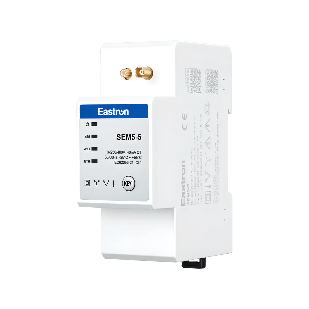
CT Operated Wifi/Ethernet/RS485 Three Phase Multi-function Energy Meter
Electrical systems are no longer isolated networks that can be managed through occasional manual readings. Energy costs, carbon-reduction targets, equipment protection, power-quality expectations, and renewable-energy integration all require continuous information. A facility manager may need to know how much energy is being consumed by a production line, whether a photovoltaic system is exporting power, or whether an imbalance is developing between phases.
A single measurement value is rarely enough to explain system behavior. A high current reading may be caused by increased production, a low power factor, or an abnormal operating condition. A high energy bill may result from longer operating hours, inefficient equipment, or an unexpected export-import pattern. By measuring several electrical parameters together, the SEM5-5 helps users interpret the condition of the system rather than simply record one number.
Communication is equally important. A meter installed in a distribution cabinet may be difficult to access physically, particularly when it is located in a plant room, remote technical space, solar installation, or multi-tenant building. RS485 communication provides a robust wired connection for industrial networks. Ethernet enables integration with TCP-based systems and existing local networks. Wi-Fi provides an additional option where new communication cabling would be inconvenient or expensive.
This combination allows the meter to be selected according to the installation. A panel builder may use RS485 for a stable multidrop network. A building integrator may use Ethernet to connect the device directly to a supervisory platform. A retrofit project may use Wi-Fi to avoid opening walls or installing new data cable. The result is greater installation flexibility than that offered by a meter with only one communication interface.
The SEM5-5 is a CT-operated AC energy meter with a compact DIN-rail form factor. It is intended for measurement in single-phase and three-phase systems, including 1P2W, 3P3W, and 3P4W configurations. Its current-transformer input architecture allows it to measure installations where the circuit current is too high for direct connection to the meter or where isolation between the power conductor and the measuring circuit is required.
The meter supports three-phase AC measurement with RMS values that include harmonics. This gives the device a more meaningful representation of electrical conditions than a measurement approach based only on ideal sinusoidal waveforms. Modern loads such as variable-speed drives, switching power supplies, LED drivers, inverters, and data-center equipment can distort current waveforms. A measurement system that considers harmonic content is better suited to contemporary installations.
The device is approximately two modules wide, or about 36 millimeters, making it suitable for space-constrained distribution boards. Its compact design can help panel manufacturers increase circuit density while preserving a clean and organized layout. It can also simplify retrofit work where available DIN-rail space is limited.
Several terminals are equipped with spring terminals or RJ-style connections to support quick installation. These connection options can reduce wiring effort and support easier maintenance. A plug-in approach may be especially valuable in systems that require repeated installation of identical meters across multiple cabinets or sites.
The meter can measure and display voltage, frequency, current, power, active energy, reactive energy, power factor, and energy direction. These values can be used for local observation, control-system integration, energy reporting, load analysis, and fault investigation.
It supports active-energy measurement to Class 1 according to the stated standards and reactive-energy measurement to Class 2. The stated power measurement accuracy is ±1 percent according to IEC 61557-12 Class 1. Current and voltage accuracy are specified at ±0.5 percent, frequency accuracy at ±0.1 percent, and power-factor accuracy at ±0.01.
The data update rate is 100 milliseconds. This allows connected systems to receive frequent updates for monitoring dashboards, control logic, demand analysis, and rapid evaluation of changing loads. The update rate does not replace a dedicated protection relay or high-speed power-quality analyzer, but it provides a useful level of responsiveness for energy-management applications.
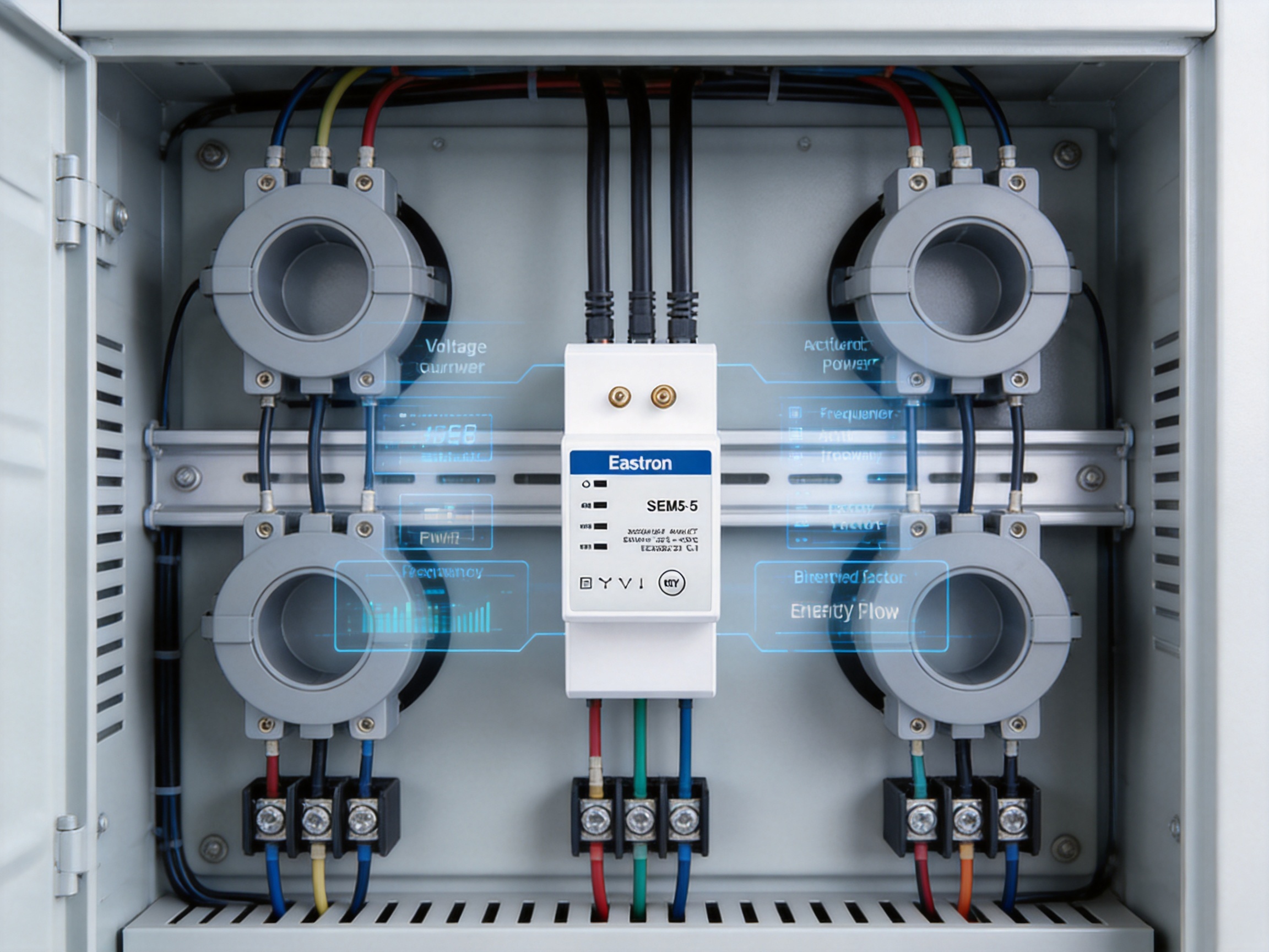
One of the product’s major advantages is its support for multiple wiring arrangements. The meter can be used with 1P2W single-phase systems, 3P3W three-phase three-wire systems, and 3P4W three-phase four-wire systems. This flexibility reduces the need to select completely different product families for different projects.
In a 1P2W installation, the meter can be used to monitor a single-phase load, branch circuit, small building supply, or individual equipment circuit. In a 3P3W installation, it can measure a three-phase system without a neutral conductor. In a 3P4W installation, it can monitor a three-phase, four-wire network with a neutral connection, which is common in commercial buildings, industrial facilities, and distribution systems.
The device also supports one three-phase load or three single-phase load measurements, depending on the selected configuration and application requirements. This can be useful for submetering, where several individual circuits are monitored within the same general installation. Engineers should configure the wiring, current transformers, phase relationships, and communication registers according to the installation design and the manufacturer’s instructions.
Current-transformer operation provides several practical benefits. It allows the meter to measure higher-current circuits without placing the full load current directly through the measuring device. It can also provide electrical separation and make installation more practical in distribution systems with large conductors or busbars.
CT-operated measurement is particularly suitable for main incomers, feeder circuits, generator outputs, photovoltaic connections, and industrial machinery. The current transformer must be selected with a suitable ratio, accuracy, burden, insulation rating, and installation method. Correct CT orientation is essential when import and export energy or directional power is being monitored. Incorrect polarity can cause the meter to report reversed power flow or inaccurate energy direction.
For safe operation, current transformers must be installed and handled by appropriately qualified personnel. The secondary circuit should never be left open while the primary circuit is energized unless the CT and installation method are specifically designed for that condition. Proper shorting, isolation, and commissioning procedures are important parts of any CT-operated metering project.
Accuracy is central to the value of an energy meter. If a device is used for energy management, internal cost allocation, production analysis, or photovoltaic optimization, measurement errors can lead to incorrect decisions. The SEM5-5 is designed to provide consistent measurement across the principal electrical parameters used in energy monitoring.
| Parameter | Specification | Application Significance |
|---|---|---|
| Measurement system | RMS including harmonics on three-phase AC systems | Suitable for modern nonlinear and electronic loads |
| Power accuracy | ±1%, IEC 61557-12 Class 1 | Supports load monitoring and energy analysis |
| Active energy accuracy | ±1%, IEC 61557-12 Class 1 and IEC 62053-21 Class 1 | Useful for submetering and consumption records |
| Reactive energy accuracy | ±2%, IEC 61557-12 Class 2 | Supports power-factor and reactive-load analysis |
| Current accuracy | ±0.5% | Useful for feeder and equipment loading information |
| Voltage accuracy | ±0.5% | Supports supply-condition monitoring |
| Frequency accuracy | ±0.1% | Provides information about system frequency |
| Power-factor accuracy | ±0.01 | Helps identify inefficient or highly reactive loads |
| Data update rate | 100 milliseconds | Provides frequently refreshed monitoring data |
The measurement input is designed for nominal three-phase voltage of 3 × 230 volts line-to-neutral or 400 volts line-to-line. The working range is 100 to 277 volts AC line-to-neutral and 173 to 480 volts AC line-to-line. The frequency range is 50 or 60 hertz, supporting common electrical standards in international markets.
Because the device measures both active and reactive energy, it can support a more complete understanding of consumption. Active energy represents useful electrical work delivered to loads, while reactive energy is associated with the energy exchange created by inductive and capacitive equipment. Monitoring both values can help users evaluate power-factor correction, transformer loading, motor operation, and network efficiency.
Power-factor measurement adds another layer of information. A low power factor can increase current for the same useful power, potentially contributing to higher losses, greater voltage drop, and reduced available capacity. With the meter connected to a monitoring system, operators can identify areas where correction equipment, load balancing, or equipment upgrades may be appropriate.
A major advantage of this product is its three communication paths: RS485, Ethernet, and Wi-Fi. Each method has different strengths, and the availability of all three in one meter gives system designers more options during project planning and future expansion.
RS485 is widely used in industrial automation and building-control systems because it can support long cable runs and multidrop networks. The SEM5-5 uses Modbus RTU, a common protocol that allows a controller, gateway, PLC, or building-management system to read electrical parameters from the meter.
The communication address range is 1 to 247. The interface operates in half-duplex mode, with selectable transmission speeds from 2400 to 115200 bits per second. None, odd, or even parity can be selected, and one or two stop bits are supported. These settings allow the meter to be matched with a wide range of existing Modbus networks.
The stated maximum transmission distance is up to 1,000 meters under suitable installation conditions. Actual performance depends on cable type, network topology, termination, electromagnetic interference, baud rate, grounding, and the number of connected devices. Correct RS485 practice remains important: use suitable twisted-pair cable, avoid unnecessary star topologies, apply termination where required, and configure all devices consistently.
Compared with meters that depend exclusively on proprietary software or a single communication method, Modbus RTU provides a broadly recognized integration route. This can simplify connection to third-party control systems and reduce dependence on one specific automation platform.
Ethernet communication provides a direct connection to an IP-based network. The SEM5-5 uses Modbus TCP, allowing energy data to be read by industrial computers, supervisory systems, data servers, building-management platforms, and other network-enabled equipment.
The default IP address is 192.168.1.200, with port 502, subnet mask 255.255.255.0, and gateway 192.168.1.1. DHCP is off by default. A static configuration can be advantageous in industrial and building-management networks because the address remains predictable for the supervisory system. Network administrators should change default settings where required by the project’s cybersecurity policy.
Ethernet can be particularly useful when a facility already has structured network infrastructure. It may allow meters installed in different electrical rooms to communicate with a central monitoring server without requiring a separate serial network. It can also simplify connection to remote dashboards and data-logging applications, provided that the network is properly segmented and secured.
Wi-Fi communication provides a wireless alternative for applications where Ethernet cabling is difficult to install. The meter operates in the 2.4 to 2.5 gigahertz radio band and supports IEEE 802.11 b/g/n. The maximum RF power is specified as less than 20 dBm.
The stated Wi-Fi range is up to 30 meters indoors and 50 meters outdoors, depending on local conditions. Metal distribution cabinets, reinforced concrete, machinery, walls, other wireless networks, and electromagnetic interference can reduce the actual range. A wireless site survey is recommended for critical installations.
Wi-Fi can reduce retrofit time in existing buildings. It may be suitable for temporary monitoring, distributed submetering, small commercial facilities, or locations where a local wireless network is already available. The availability of wired RS485 and Ethernet alongside Wi-Fi also provides a fallback option if the wireless environment changes.

The SEM5-5 is positioned as a multifunction communications meter rather than a simple display-only device. Its advantages become most apparent when it is compared with common alternatives used in basic energy-monitoring projects.
A basic energy counter may provide accumulated kilowatt-hours but little information about the conditions that produced that consumption. The SEM5-5 adds voltage, current, power, frequency, reactive energy, power factor, and directional energy information. This helps users move from passive recording toward active energy management.
For example, if consumption rises, the operator can compare active power, current, power factor, and phase values to determine whether the cause is a new load, an inefficient motor, an imbalanced distribution system, or a change in operating conditions. More data supports better diagnosis and more targeted corrective action.
Some competing meters offer only RS485, while others require a separate gateway for Ethernet or wireless connectivity. By combining RS485, Ethernet, and Wi-Fi options, the SEM5-5 can reduce the number of interface components required in many applications.
A system designer can select the most suitable interface during commissioning or project development. The same meter family can therefore be used in a serial automation network, an IP-based building system, or a wireless retrofit project. This can simplify procurement, training, spare-parts management, and maintenance.
Large multifunction analyzers may require more panel space and more complex mounting arrangements. The approximately 36-millimeter, two-module design of the SEM5-5 is intended for compact distribution boards. Space savings can be important in data closets, small control panels, modular switchboards, and retrofit enclosures.
The ability to work with 1P2W, 3P3W, and 3P4W systems gives the product a wider application range than a meter designed for only one wiring arrangement. This is useful to electrical contractors and system integrators who work across residential, commercial, industrial, and renewable-energy projects.
Photovoltaic systems require more than ordinary consumption measurement. Operators may need to distinguish imported energy from exported energy, monitor generation, evaluate self-consumption, and understand the relationship between solar production and site demand. The SEM5-5 supports PV modes and import/export direction measurement, making it suitable for energy-flow monitoring around photovoltaic installations.
Solar installations often combine generation, storage, grid connection, and variable site consumption. This creates a need for meters that can identify power direction and communicate frequently with a control or monitoring platform.
The SEM5-5 can be installed at a grid connection point, photovoltaic feeder, building incomer, or selected load circuit, depending on the system architecture. By measuring active power and energy direction, it can help determine whether the site is drawing energy from the grid or sending excess generation outward.
In a self-consumption project, the meter can provide information used to compare on-site generation with building demand. In an export-limited system, its data may support a controller that adjusts inverter output or coordinates loads. In a multi-meter installation, individual meters can be placed at generation and consumption points to create a more complete energy-flow model.
The meter is not itself a complete photovoltaic controller, protection device, or grid-compliance system. However, its measurement and communication capabilities can serve as an important data source for those systems. Final system design must take account of local electrical regulations, inverter requirements, protection coordination, CT accuracy, and utility requirements.
Smart buildings depend on reliable information from electrical distribution systems. Energy meters can be installed at main incomers, tenant supplies, lighting distribution boards, HVAC feeders, elevators, data rooms, and electric-vehicle charging circuits.
In a commercial building, the SEM5-5 can support tenant submetering and internal allocation. Facility managers can compare consumption among floors, departments, or leased areas. This may encourage more efficient behavior and help identify unusual consumption patterns.
For HVAC systems, electrical measurement can be compared with operating schedules, indoor conditions, and weather information. A sudden rise in current or a decline in power factor may indicate a maintenance issue or changing equipment behavior. For lighting systems, submetering can show the impact of LED upgrades, occupancy controls, or schedule changes.
Because the meter provides Ethernet, Wi-Fi, and RS485 communication, it can be adapted to different building-control architectures. A new building may use Ethernet and a centralized IP network. A retrofit project may use Wi-Fi in areas where new cabling is difficult. A technical plant room may use RS485 to connect a group of meters to a local controller.
Manufacturing facilities often contain many high-power loads, including motors, pumps, compressors, heaters, conveyors, welding equipment, and variable-frequency drives. Understanding the energy profile of each process can help manufacturers reduce waste, allocate production costs, and identify equipment problems.
The SEM5-5 can be used to monitor individual machines or production feeders through current transformers. Active power data can be compared with production output to calculate energy intensity. Reactive energy and power-factor information can assist in evaluating motors and correction systems. Phase current and voltage data can help identify imbalance or supply issues.
For maintenance teams, trend data can provide an additional condition indicator. A gradual increase in current under the same operating conditions may suggest mechanical wear, blockage, bearing problems, or process changes. Electrical data should not replace mechanical inspection or dedicated condition-monitoring equipment, but it can provide a cost-effective first layer of observation.
In an industrial network, RS485 Modbus RTU can connect meters to a PLC or supervisory controller. Ethernet Modbus TCP can connect them to a plant network or manufacturing execution system. The choice depends on the existing infrastructure, control requirements, cybersecurity design, and physical conditions of the site.
Data centers, telecommunications facilities, laboratories, and other critical sites require detailed visibility into power distribution. Operators may monitor incoming power, uninterruptible power supply outputs, server-room feeders, cooling equipment, and backup systems.
The compact form factor can be useful in densely populated panels where space is limited. Ethernet connectivity can support integration into an existing monitoring network, while RS485 can be used for local cabinet-level communication. Wi-Fi may be useful for temporary commissioning or noncritical supplementary monitoring, although critical facilities should always follow their own communication and cybersecurity standards.
Voltage, current, power, frequency, and power factor provide useful information about the electrical condition of equipment. Active and reactive energy values can support operational reporting. Import/export measurement may be relevant where a facility includes on-site generation, energy storage, or demand-response equipment.
Correct installation is essential for accurate measurement and safe operation. The meter should be mounted on a suitable DIN rail inside an enclosure appropriate for the electrical environment. The installer should verify the supply voltage, system frequency, phase arrangement, CT ratio, CT orientation, communication wiring, and protective arrangements before energization.
The voltage inputs must be connected according to the selected 1P2W, 3P3W, or 3P4W configuration. CT secondary connections must be assigned to the corresponding phases. Phase matching is important: the voltage reference for a phase must correspond to the current transformer installed on that phase. Incorrect phase association can produce inaccurate power, energy, and power-factor readings even when voltage and current values appear reasonable.
After installation, commissioning should include verification of voltage readings, current readings, phase sequence, power direction, active power, reactive power, accumulated energy, and communication response. If the system is monitoring photovoltaic generation, import/export direction should be checked under both generation and consumption conditions.
For RS485 networks, the address, baud rate, parity, and stop-bit settings must match the master device. For Ethernet and Wi-Fi, the IP configuration, port, subnet, gateway, and network permissions should be confirmed. Default network settings should be reviewed and changed when necessary.
Installers should also consider the location of the antenna and the effect of metal enclosures on wireless performance. Where the meter is installed in a metal cabinet, the practical Wi-Fi range may be significantly lower than the open-air specification. Ethernet or RS485 may be the preferred option for stable long-term communication in such conditions.
Product performance depends not only on the published specification but also on the design, testing, production control, and support systems behind the product. Eastron Electronic Co., Ltd. develops and manufactures electricity meters, power analyzers, current sensors, communication modules, and energy-management products.
The company is headquartered in Jiaxing, China, in a region with close access to major technology, manufacturing, logistics, and research centers. Its development teams in China and the United Kingdom support product innovation and international market requirements. Cooperation with universities and research institutions helps connect practical product development with advanced electrical and embedded technologies.
The company maintains a professional laboratory capable of carrying out EMC, low-voltage directive, accuracy, and environmental testing according to IEC, EN, GB, and UL-related requirements. These test capabilities are valuable because energy meters operate in electrically active environments where electromagnetic interference, temperature changes, voltage variation, and installation conditions can influence performance.
Testing during development can help identify weaknesses before products reach volume production. EMC testing evaluates resistance to interference and the potential for the meter to disturb nearby equipment. Accuracy testing verifies measurement behavior against reference equipment. Environmental testing evaluates performance under conditions such as temperature and humidity variation. Low-voltage testing supports electrical safety evaluation.
The company follows an ISO 9001 quality-management system. It also reports patented technologies in software, embedded software, and hardware, as well as recognition as a high-tech enterprise and high-tech research and development center for electricity applications. These capabilities support the development of products that combine measurement electronics, digital processing, embedded firmware, communication protocols, and compact mechanical design.
Manufacturing strength is especially important for connected meters because the product must perform several functions at once. The input circuitry must accurately process voltage and CT signals. The embedded system must calculate electrical values and manage energy registers. The communication subsystem must maintain reliable data exchange. The power supply and insulation design must operate safely inside a distribution board. A weakness in any one area can affect the overall user experience.
By combining research, laboratory validation, production experience, and technical support, the manufacturer can provide a more complete solution than a supplier focused only on low-cost hardware. This is particularly important for projects involving many meters, long service life, third-party integration, and international compliance expectations.
Connected energy meters are software-defined measurement devices as well as electrical instruments. Embedded software converts sampled voltage and current signals into useful values, manages energy accumulation, handles import and export direction, updates communication registers, and supports configuration.
Reliable firmware should maintain stable operation under changing loads and communication activity. It should present data consistently through local and remote interfaces and preserve accumulated energy information according to the product design. Modbus integration requires clear register mapping, predictable data types, and appropriate response behavior.
The SEM5-5 specifies floating-point data for RS485 and network communications. This can simplify the representation of electrical values with decimal precision. System integrators should nevertheless review the complete communication map, byte order, scaling rules, signed or unsigned interpretation, and energy-register behavior before final programming.
Its RS485 response time is specified as less than 100 milliseconds. This supports responsive polling in many monitoring systems. Actual network scan time will depend on baud rate, the number of devices, polling strategy, register quantity, controller performance, and network traffic.
A single meter can provide useful information for one feeder, but the greatest value often comes from a coordinated metering system. Multiple SEM5-5 units can be installed at different levels of an electrical distribution hierarchy, such as the main incomer, subdistribution board, production line, and individual machine.
At the main level, the system can measure total consumption or exchange with the grid. At the subdistribution level, it can identify the energy used by departments or building services. At the equipment level, it can show the consumption of specific production assets. Comparing these levels may reveal losses, unmetered circuits, or opportunities for efficiency improvement.
System designers should determine the required measurement points, communication architecture, polling interval, data-retention period, alarm thresholds, and dashboard requirements before installation. It is also useful to define which values must be recorded for billing allocation and which are intended only for operational analysis.
RS485 is often suitable for a local group of meters, while Ethernet can link separate panels or buildings. Wi-Fi can supplement the system in areas where cabling is not practical. Gateways may be used to connect Modbus data to cloud platforms, enterprise software, or remote-access systems. The meter’s open communication approach allows it to be incorporated into broader energy-management solutions rather than isolated as a standalone instrument.
Measurement is the foundation of energy efficiency. Without reliable data, organizations may rely on assumptions or isolated utility bills. A multifunction meter can provide the detailed information needed to establish a baseline, identify peak demand, compare operating periods, and verify the results of improvement projects.
For example, a facility may install meters before and after replacing motors, improving power-factor correction, changing production schedules, or upgrading lighting. The resulting data can show whether the expected reduction actually occurred. If the result is different from the forecast, the electrical measurements can help explain why.
Energy data can also support preventive action. A persistent phase imbalance may indicate uneven load distribution. A falling power factor may indicate changes in motor loading or capacitor-bank performance. Increasing reactive energy may suggest a need for inspection. An unexpected export reading may reveal incorrect CT orientation or an unusual generation condition.
In photovoltaic systems, energy-direction measurement can help distinguish site consumption from grid export. This can support decisions about battery charging, flexible loads, electric-vehicle charging, or inverter control. In buildings, submetering can make energy use visible to departments and tenants. In factories, machine-level data can support energy-per-unit analysis.
Before selecting and installing the meter, users should confirm several technical points. First, the electrical system must match one of the supported wiring configurations. Second, the voltage range and frequency must be suitable. Third, the CT ratio and accuracy must match the expected current and measurement objective.
The communication method should be selected based on distance, infrastructure, environmental conditions, cybersecurity requirements, and maintenance preferences. RS485 is a strong option for structured industrial networks. Ethernet is convenient where IP infrastructure is available. Wi-Fi is attractive for retrofits and short-to-medium range wireless applications, but the site should be checked for signal quality.
Users should also determine whether they need active energy only or a complete set of electrical parameters. If the system requires high-order harmonic analysis, transient capture, waveform recording, or advanced power-quality compliance functions, a dedicated power-quality analyzer may be more appropriate. The SEM5-5 is primarily a compact multifunction energy meter for monitoring, analysis, and system integration.
Project teams should specify the desired data-logging platform and verify compatibility with Modbus RTU or Modbus TCP. They should also plan network addresses and avoid duplicate IP addresses or Modbus slave addresses. For larger projects, documentation of meter location, CT ratio, phase mapping, communication parameters, and commissioning results can greatly simplify future maintenance.
Energy meters generally require less routine maintenance than mechanical equipment, but periodic verification remains valuable. Connections should be inspected for looseness, overheating, corrosion, or physical damage. CT wiring and polarity should be checked if measurements appear inconsistent. Network communication should be monitored for intermittent faults.
Keeping accurate documentation is an important maintenance practice. Records should include the meter model, installation date, CT ratio, wiring configuration, IP address, Modbus address, communication settings, and any calibration or verification results. This information helps service personnel troubleshoot problems without interrupting the entire facility.
The manufacturer’s technical support and after-sales service capabilities are also important. Eastron serves customers in more than 50 countries across Europe, Asia-Pacific, America, the Middle East, and Africa. International project experience can help address differences in electrical systems, communication requirements, compliance expectations, and installation practice.
For large installations, maintaining a small number of spare units can reduce downtime. Because the SEM5-5 supports several system types and communication options, a common product platform may simplify spare-parts management across multiple sites.
Installation and service work on energized electrical systems can be dangerous. The meter should be installed only by qualified personnel who understand electrical safety, current-transformer circuits, protective devices, and local regulations. The installation must include appropriate isolation, overcurrent protection, enclosure protection, grounding, and labeling.
Current-transformer secondary circuits require particular attention. An open-circuit CT secondary can create hazardous voltage. Installers must follow the CT manufacturer’s instructions and use suitable shorting or disconnect arrangements where required. The meter’s communication connections should also be separated and routed appropriately to reduce interference and maintain safe clearances.
Network security should be considered from the beginning of the project. Default IP addresses, passwords, wireless credentials, and access permissions should be reviewed. Meters should be placed on appropriately managed networks, and unnecessary external access should be restricted. Modbus itself does not provide comprehensive cybersecurity, so system-level protection is necessary.
Electrical systems are becoming more distributed, digital, and interactive. Solar generation, batteries, electric vehicles, heat pumps, flexible loads, and automated building systems all change the direction and timing of power flow. A meter that only records total consumption may not provide enough information for this environment.
The SEM5-5 is suited to this transition because it combines directional energy measurement, multiple electrical parameters, CT operation, flexible wiring configurations, and three communication methods. Its compact format supports dense installations, while Modbus compatibility allows integration with a wide range of control and monitoring platforms.
The optional LoRa capability can further expand deployment possibilities in selected applications where long-range, low-power wireless communication is appropriate. The exact suitability of LoRa depends on the ordered product configuration, network architecture, data requirements, and local radio conditions.
Future-ready measurement does not mean that every installation must use every available interface. Instead, it means that the product gives the system designer room to adapt. A site may begin with local RS485 monitoring and later migrate selected meters to Ethernet. A retrofit may begin with Wi-Fi and later adopt structured cabling. A photovoltaic project may add additional meters as generation and storage capacity expand.

The SEM5-5 is a CT-operated AC multifunction energy meter for single-phase and three-phase electrical systems. It supports 1P2W, 3P3W, and 3P4W configurations and is designed for DIN-rail installation.
It can measure voltage, current, frequency, power, active energy, reactive energy, power factor, and import or export energy direction. It is designed to measure RMS values including harmonics on three-phase AC systems.
Yes. PV modes are available, and the meter can measure import and export direction. It can provide electrical data for photovoltaic monitoring, self-consumption analysis, export monitoring, and energy-management systems. It is not a replacement for an inverter controller or protective device.
RS485 communication uses Modbus RTU. Ethernet and Wi-Fi communication use Modbus TCP. The availability of all three options supports a variety of industrial, building, and retrofit network designs.
The Wi-Fi interface operates from 2.4 to 2.5 gigahertz and supports 802.11 b/g/n. The stated range is up to 30 meters indoors and 50 meters outdoors, although actual performance depends on walls, cabinets, interference, antenna location, and local conditions.
The stated default IP address is 192.168.1.200. The default port is 502, the subnet mask is 255.255.255.0, the gateway is 192.168.1.1, and DHCP is off by default. Network administrators should review and change these settings as required.
The stated maximum transmission distance is up to 1,000 meters under suitable conditions. Actual distance depends on cable selection, baud rate, termination, topology, electromagnetic interference, and the number of connected devices.
Active energy is specified at ±1 percent according to IEC 61557-12 Class 1 and IEC 62053-21 Class 1. Reactive energy is specified at ±2 percent according to IEC 61557-12 Class 2.
The meter has a compact width of approximately two DIN modules, or about 36 millimeters. This makes it suitable for distribution boards and control cabinets where panel space is limited.
The product supports one three-phase load or three single-phase load measurements, depending on the selected configuration and wiring arrangement. The installation should follow the official wiring diagram and configuration instructions.
The CT ratio, rated current, accuracy, polarity, phase assignment, insulation, and secondary-circuit safety should all be checked. The voltage reference and current transformer for each phase must correspond correctly to obtain accurate power and energy-direction readings.
The meter provides Class 1 active-energy measurement according to the stated standards, making it suitable for many monitoring and submetering applications. Whether it can be used for formal billing or revenue metering depends on local regulations, certification requirements, installation conditions, and the exact product configuration.
In addition to accumulated active energy, it provides several electrical parameters, reactive-energy information, power-factor data, directional energy measurement, and multiple communication options. This makes it more useful for system analysis and energy-management integration.
The product is manufactured by Eastron Electronic Co., Ltd., a company specializing in electricity meters, power analyzers, current sensors, communication modules, and energy measurement solutions.
The CT-operated Wi-Fi, Ethernet, and RS485 three-phase multifunction energy meter provides a practical combination of measurement depth, communication flexibility, compact installation, and application versatility. It is designed for electrical systems that require more information and connectivity than a basic energy counter can provide.
Its support for 1P2W, 3P3W, and 3P4W systems allows it to serve a broad range of installations. CT operation makes it suitable for larger feeders and equipment circuits. Measurement of voltage, current, power, active and reactive energy, frequency, power factor, and energy direction supports more informed operational decisions. Modbus RTU, Modbus TCP through Ethernet, and Modbus TCP through Wi-Fi provide flexible routes into existing and future monitoring architectures.
Compared with single-interface or display-only meters, the product offers stronger integration potential and greater visibility into electrical conditions. Its compact two-module design, spring or RJ-style connection options, PV modes, and optional LoRa capability further improve its suitability for modern energy projects.
Behind the product is a manufacturer with experience in electricity measurement, embedded technology, laboratory testing, quality management, and international support. Eastron’s own EMC, low-voltage, accuracy, and environmental testing capabilities help support dependable product development and validation.
For photovoltaic systems, smart buildings, industrial equipment, commercial distribution boards, and energy-management projects, the SEM5-5 can serve as a reliable measurement layer between the electrical installation and the digital systems responsible for monitoring, analysis, and control.
IEC 61557-12, Electrical Safety in Low-Voltage Distribution Systems, Measurement and Monitoring Equipment.
IEC 62053-21, Electricity Metering Equipment, Static Meters for Active Energy, Class 1 and Class 2.
Modbus Organization, Modbus Application Protocol Specification.
Modbus Organization, Modbus over Serial Line Specification and Implementation Guide.
IEEE 802.11 Wireless LAN Standards.
ISO 9001, Quality Management Systems — Requirements.
Manufacturer technical documentation for the SEM5-5 multifunction energy meter.
Manufacturer information concerning electricity meters, power analyzers, current sensors, communication modules, and energy measurement solutions.
Your email address will not be published. Required fields are marked *

We develop and produce high performance electricity meters, power analyzers, current sensors, communication modules and management systems.
Address:NO. 52, Dongjin Road, Nanhu, Jiaxing, Zhejiang, China
Copyright @ Eastron Electronic Co., Ltd. All rights reserved
