

 English
 Español
 Deutsch
 中文简体


Product Consultation
Your email address will not be published. Required fields are marked *
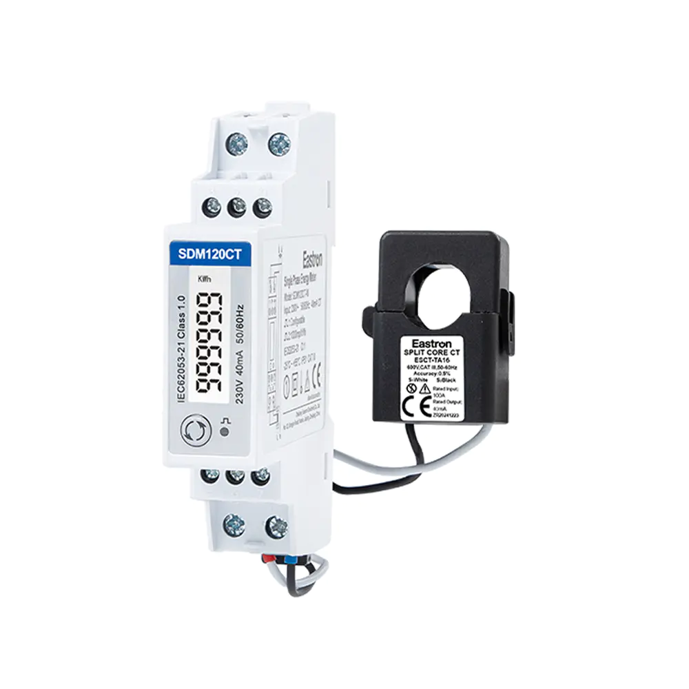
RCM 40mA CT Input Din Rail Single Phase Multi-function Solar PV /Zero Export Meter for PV Metering
Nov 24,2022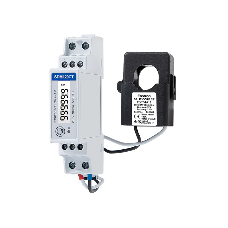
MID/RCM 100mA CT input Din Rail Single Phase Multi-function Solar PV /Zero Export Meter for PV Metering
Nov 24,2022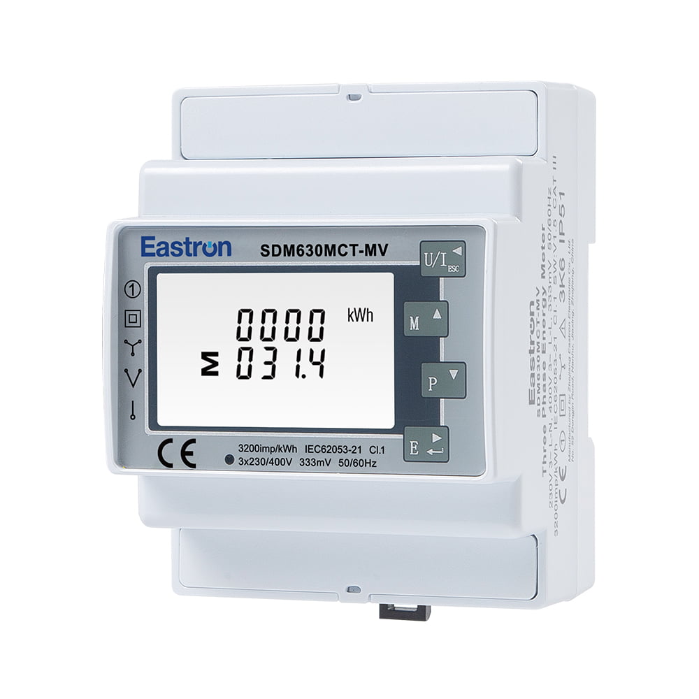
RCM CT Type Din Rail Three Phase Multi-function Solar PV /Zero Export Meter for PV Metering
Aug 03,2022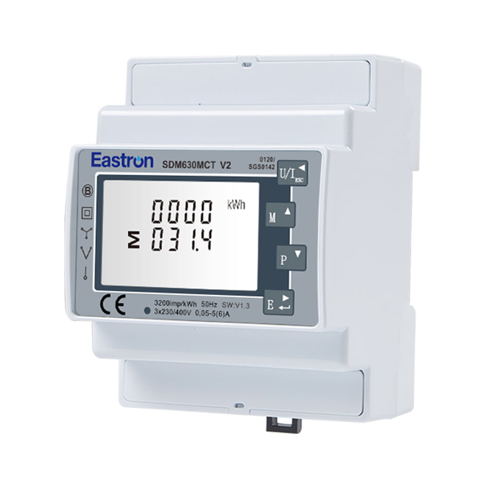
MID Approved CT Type Din Rail Three Phase Multi-function Solar PV /Zero Export Meter for PV Metering
Nov 24,2022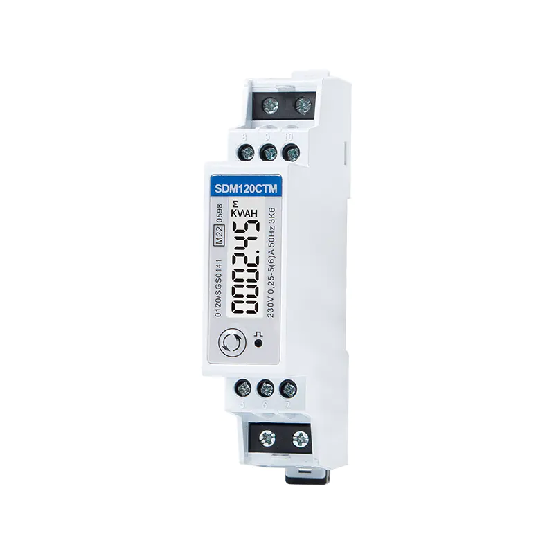
MID CT Type Din Rail Single Phase Multi-function Solar PV /Zero Export Meter for PV Metering
Nov 24,2022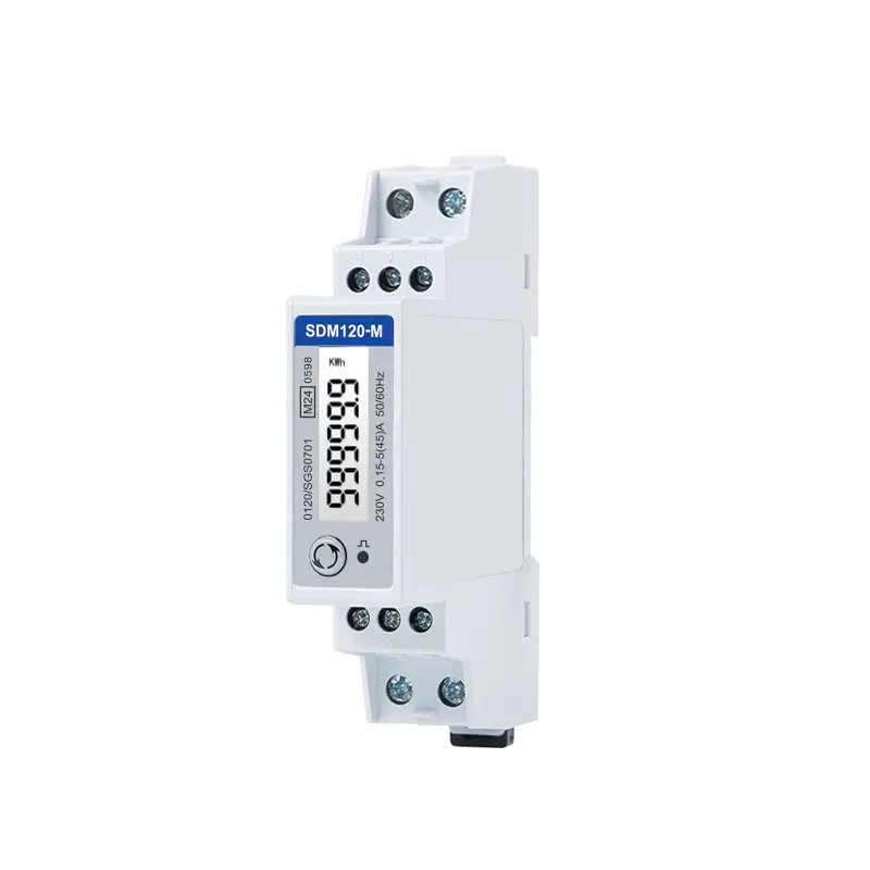
MID Din Rail Single Phase Multi-function Solar PV /Zero Export Meter for PV Metering
Jul 26,2022Content
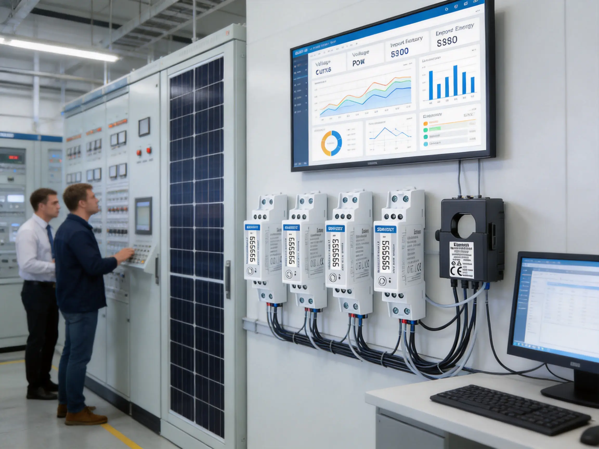
Solar photovoltaic installations are becoming increasingly sophisticated. Modern systems must do more than generate electricity: they must measure imported and exported energy, monitor electrical quality, support remote communication, coordinate with energy management platforms, and help operators comply with grid and site requirements. A compact meter that combines these functions can simplify system design while improving visibility, control, and operating efficiency.
The SDM120CT 40mA is a single-phase, multifunction energy meter designed for solar PV metering, zero-export systems, distributed energy installations, and other low-voltage monitoring applications. Its DIN-rail format, 18 mm width, current-transformer input, bidirectional measurement, pulse outputs, and optional communication interfaces make it suitable for applications where panel space is limited but measurement requirements are extensive.
Built for a 1P2W single-phase system, the meter measures active and reactive energy together with voltage, current, power, power factor, frequency, and demand-related values. Depending on the selected version, it can provide two pulse outputs, RS485 Modbus RTU, or M-Bus communication. This combination allows the meter to function as a local energy counter, a data source for an inverter controller, or a node in a larger energy-management network.
In a conventional electrical installation, a meter may simply record total consumption. In a photovoltaic system, however, the direction and timing of energy flow are equally important. Electricity can move from the utility grid to the building, from the PV array to the building, or from the PV array back to the grid. A suitable meter must distinguish these operating conditions and record them correctly.
Bidirectional measurement is especially important in zero-export applications. A zero-export controller uses real-time measurements at the grid connection point to adjust inverter output. If the system detects that energy is being exported, the controller can reduce PV generation or redirect energy to a battery or other load. If the building is importing electricity, the controller can permit more PV generation when operating conditions allow.
Measurement errors, slow response, or incorrect polarity can compromise this process. The resulting system may export energy unintentionally, curtail generation unnecessarily, or fail to provide reliable data for operators. A dedicated bidirectional meter with communication capability offers a more dependable foundation for monitoring and control.
The SDM120CT 40mA is designed to address these requirements in a compact form. It can measure imported and exported active energy, provide pulse indications for energy accumulation, and transfer measurements to a supervisory controller through a communication interface. Its small footprint makes it practical for compact distribution boards, inverter cabinets, and control enclosures.
RCM 40mA CT Input Din Rail Single Phase Multi-function Solar PV /Zero Export Meter for PV Metering
The meter is a single-phase multifunction device for 1P2W systems. It measures RMS values on a single-phase AC network and is intended for installation on a standard DIN rail. At only one module, or approximately 18 mm in width, it uses considerably less enclosure space than many conventional multifunction meters.
The current input is designed for a 40 mA CT-operated configuration. Current transformers allow the measurement circuit to be electrically separated from the high-current conductor. This arrangement is useful when the monitored current is too high for direct connection or when a system designer wants greater flexibility in sensor placement and wiring.
The product information also identifies optional current-input configurations, including 100 mA and 100 mV versions. These alternatives can support different sensor technologies and project requirements. Because CT input specifications vary by model and ordering code, the system designer should confirm the exact input type, CT ratio, and compatible sensor before placing an order.
The meter measures a broad group of electrical parameters:
• Active energy in both import and export directions.
• Reactive energy.
• Voltage.
• Current.
• Active power.
• Power factor.
• Frequency.
• Demand and related operating values, depending on the configured version and communication register map.
Two pulse outputs are available for energy measurement applications. These outputs may be assigned to imported and exported energy, allowing external counters, PLCs, building-management systems, or data loggers to receive discrete energy pulses.
The communication version provides RS485 with Modbus RTU. The M-Bus version provides communication according to EN 13757-3. These options allow the product to be matched to the architecture already used at a site rather than forcing the installer to redesign the complete monitoring system.
One of the most visible advantages is the meter’s 18 mm, one-module width. Electrical cabinets are increasingly crowded with circuit protection, contactors, surge protection, inverter controls, communication equipment, and terminal blocks. Reducing the width of the measurement device can free valuable space for additional equipment or allow the use of a smaller enclosure.
A narrow DIN-rail meter can also simplify retrofit projects. Existing photovoltaic and distribution boards may have little spare capacity. Instead of replacing a large section of the cabinet, an installer may be able to add a compact meter beside the existing protection and control devices.
Compact construction does not eliminate the need for correct spacing, wiring, thermal management, or accessibility. However, it provides a practical advantage over wider multifunction meters when installation space is limited.
Solar PV systems require measurement in both directions. The meter can distinguish energy imported from the grid from energy exported toward the grid, making it appropriate for self-consumption monitoring, export limitation, and distributed-generation applications.
Bidirectional measurement also improves reporting. A facility operator can determine how much energy was produced locally, how much was consumed on site, how much was imported, and how much was exported. These values support energy audits, system optimization, tariff analysis, and evaluation of battery-storage strategies.
A basic energy counter may provide only accumulated kilowatt-hours. The SDM120CT provides a wider electrical picture. Voltage and current values help identify abnormal operating conditions. Power and power factor indicate how the load is behaving. Frequency monitoring can help confirm the quality of the supply. Reactive energy information is useful in installations where power factor or reactive-power management is important.
Combining these measurements in one device can reduce the number of separate instruments required in the panel. It can also simplify data integration because the monitoring platform receives related values from a common measurement point.
The two pulse outputs provide a simple and widely understood method of transmitting energy information. Pulse outputs are useful when the receiving equipment does not require a full digital communication protocol or when an existing pulse-counting system is already installed.
RS485 Modbus RTU adds a more comprehensive data channel. A controller can read several electrical parameters, configure communication settings, and collect data for analysis. Modbus is widely used in photovoltaic controllers, programmable logic controllers, industrial gateways, building-management systems, and energy-monitoring software.
The M-Bus version is suitable for metering networks that use the EN 13757-3 communication framework. This is particularly useful in multi-meter installations where a central data concentrator collects readings from electricity, heat, water, or gas meters.
CT operation allows the meter to measure current through a sensor rather than placing the full load current directly through the meter terminals. This approach can improve installation flexibility and make the product suitable for circuits where direct-connected meters are not practical.
The stated product configuration uses a 40 mA CT input, with 100 mA and 100 mV options available for selected versions. The current transformer must be correctly matched to the meter input. The CT ratio, output type, polarity, burden, insulation category, and wiring method should all be checked before commissioning.
A CT-operated meter also requires attention to safe installation practice. The secondary circuit of a conventional current transformer should not be left open while the primary conductor carries current unless the sensor manufacturer specifically permits that condition. Installers should follow the applicable electrical code and the CT manufacturer’s instructions.
The meter is specified for RMS measurement on a single-phase AC system. RMS measurement provides a practical representation of the effective voltage and current in normal low-voltage networks and allows power-related values to be calculated from the measured electrical quantities.
| Measurement Item | Specification or Accuracy Class |
|---|---|
| System type | Single-phase AC, 1P2W |
| Voltage reference | 230 V rated voltage |
| Operational voltage | 80% to 120% of rated voltage |
| Power accuracy | 1% of maximum range |
| Active energy | IEC 62053-21 Class 1.0 and EN 50470-1/3 Class B |
| Reactive energy | IEC 62053-23 Class 2 and IEC 61557-12 Class 2 |
| Frequency accuracy | 0.2% of mid-frequency |
| Current accuracy | 0.5% of maximum range |
| Voltage accuracy | 0.5% of maximum range |
| Power factor accuracy | 1% of unity, with 0.01 resolution indicated |
The stated active-energy performance corresponds to Class 1.0 under IEC 62053-21 and Class B under EN 50470-1/3. This level is appropriate for many sub-metering, solar monitoring, and energy-management applications. It provides a useful balance between measurement performance, compact construction, and cost.
Reactive-energy measurement is specified to Class 2 under IEC 62053-23 and IEC 61557-12. Reactive data can help users understand the behavior of inductive or capacitive loads and can support wider power-quality and energy-efficiency programs.
Voltage and current accuracy are specified at 0.5% of maximum range. Actual system accuracy depends on the complete measurement chain, including the CT, conductor placement, wiring, temperature, waveform, installation quality, and the operating range of the instrument. For this reason, an engineering review should consider both the meter specification and the performance of the selected sensor.
The communication version uses RS485 and Modbus RTU. RS485 is a robust differential serial interface commonly used in industrial environments. It is suitable for connecting several meters along a bus, provided that the network is correctly terminated and the cable is appropriately selected.
The stated communication address range is 1 to 247. Baud rates from 1200 bps to 9600 bps are supported, with no parity identified as the default and odd or even parity also available. One or two stop bits can be selected. The specified response time is less than 100 milliseconds.
These settings provide compatibility with many supervisory controllers and gateways. During commissioning, all devices on the same RS485 segment should be assigned unique addresses. The master device and meters must use matching baud rate, parity, and stop-bit settings. Communication wiring should preserve polarity, and the network should follow recommended limits for cable length, termination, and node count.
The M-Bus version follows EN 13757-3 communication requirements. M-Bus is designed for meter reading and supports centralized data collection from multiple field devices. The stated address range is 1 to 250, with transmission speeds from 300 bps to 9600 bps.
M-Bus can be beneficial in projects where electrical meters form part of a wider utility-metering network. A central concentrator can collect readings from multiple devices and forward them to a cloud platform, local server, or building-management system.
The two pulse outputs provide a direct representation of energy accumulation. One output may be assigned to import energy and the other to export energy, depending on the product configuration and programming. Pulse data can be counted by a controller or gateway and converted into energy values using the selected pulse constant.
Pulse interfaces are attractive because they are simple, widely supported, and independent of a particular software protocol. They can serve as a backup data path or as the primary interface in a basic monitoring installation.
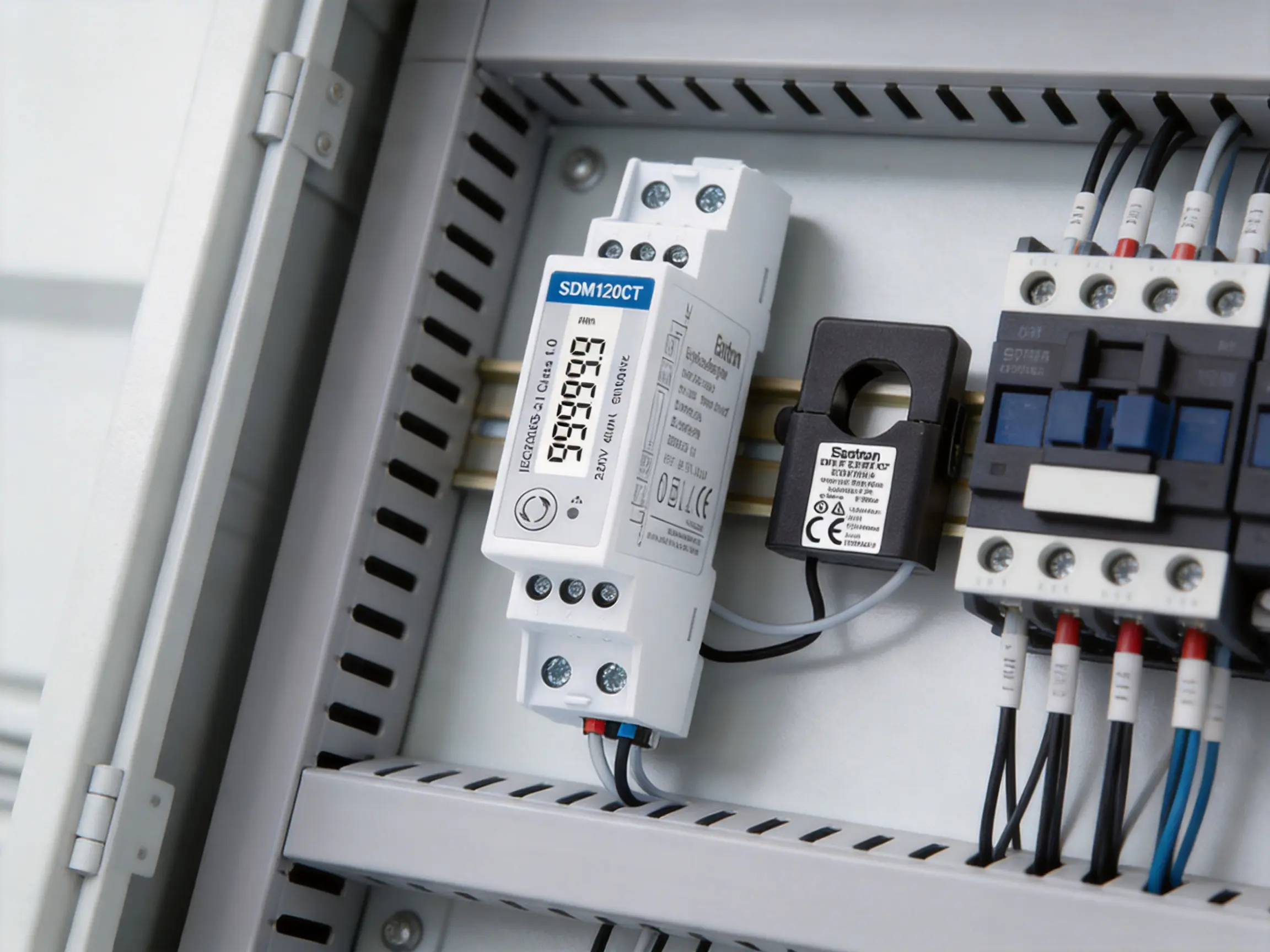
Solar PV metering is the primary application for this product. In a residential, commercial, or small industrial installation, the meter can be placed at a selected measurement point to record energy flow between the local electrical system and the grid.
When installed at the point of common coupling, the meter can help determine whether the site is importing or exporting energy. This information can be forwarded to an inverter controller, an energy-management system, or a local display. Operators can then evaluate self-consumption, identify periods of high demand, and adjust system settings.
For a small commercial building, the meter can provide a dedicated measurement channel for a photovoltaic inverter. The facility manager may use the data to compare PV generation with building demand, identify unused generation potential, and assess whether battery storage or additional controllable loads would be beneficial.
In a residential system, the product’s compact size can be particularly valuable. Residential distribution boards often have limited spare space, and the one-module format can simplify integration with existing protective devices and inverter controls.
For a multi-site solar portfolio, communication capability allows individual meters to be connected to a central monitoring platform. The operator can compare sites, identify underperforming installations, and receive alerts based on abnormal voltage, current, power factor, or energy-flow conditions.
Zero-export systems are designed to prevent or limit power flow from a local generator to the utility grid. This requirement may arise from grid-connection rules, site operating policies, contractual limitations, or the desire to maximize on-site use of solar energy.
A zero-export controller requires a measurement at the grid interface. The meter reports whether the facility is importing or exporting energy, and the controller adjusts inverter output accordingly. A fast and correctly configured measurement system helps reduce export events while preserving as much solar generation as possible.
The SDM120CT supports this application through bidirectional measurement and communication options. A controller can obtain active power and energy-flow data through Modbus, while pulse outputs can provide a separate energy signal where required.
System designers should recognize that the meter is one part of the complete control loop. Zero-export performance also depends on the inverter’s response time, controller logic, communication delay, CT placement, phase identification, load variability, and the configuration of export thresholds. Correct installation and commissioning are therefore essential.
The meter should normally be installed at the location specified by the zero-export control strategy. If the CT is positioned on the wrong side of the connection point, the controller may receive misleading data. Similarly, reversed CT polarity can cause import and export values to appear inverted.
Compared with a simple single-function kWh meter, the SDM120CT offers a wider measurement range and more communication flexibility. A basic meter may record accumulated active energy but provide little information about voltage, current, power factor, frequency, or reactive energy. This limits the ability to diagnose problems and optimize a PV installation.
Compared with direct-connected meters, a CT-operated design can be more flexible for larger or retrofit circuits. The current sensor can be selected and positioned according to the application, while the meter remains a compact control-panel device.
Compared with large multifunction power analyzers, the one-module format can reduce panel-space requirements and installation cost. A high-end analyzer may offer more advanced harmonic analysis, waveform capture, or power-quality functions, but many small PV and zero-export systems do not require those features. The SDM120CT focuses on the measurements and interfaces most commonly needed for energy-flow monitoring.
Compared with meters that provide only one communication option, the availability of pulse, Modbus, and M-Bus variants gives system integrators greater design flexibility. The most suitable version can be selected according to the controller, gateway, and existing building-management infrastructure.
| Feature | Basic kWh Meter | Large Power Analyzer | SDM120CT 40mA |
|---|---|---|---|
| Active energy measurement | Usually available | Available | Available, bidirectional |
| Reactive energy measurement | Often unavailable | Usually available | Available |
| Voltage and current monitoring | Limited or unavailable | Available | Available |
| Power factor and frequency | Often unavailable | Available | Available |
| Pulse outputs | May be available | May be available | Two outputs |
| RS485 Modbus | Optional or unavailable | Usually available | Available on selected version |
| M-Bus | Less common | Less common | Available on selected version |
| DIN-rail footprint | Varies | Often larger | One module, approximately 18 mm |
| Typical application | Basic consumption recording | Detailed power-quality analysis | PV metering, zero export, and compact energy monitoring |
The performance of an energy meter depends not only on its circuit design but also on the consistency of its manufacturing process. Small deviations in current-sensing circuits, voltage references, terminal assembly, firmware, or calibration can affect accuracy and reliability. A professional meter manufacturer must therefore control design, production, testing, and documentation as a connected process.
Eastron Electronic Co., Ltd. operates as a specialist manufacturer of electricity meters, power analyzers, current sensors, communication modules, and energy-management products. Its product development and manufacturing activities are supported by technical teams in China and the United Kingdom, enabling the company to combine engineering resources across different markets.
The company has established a professional laboratory for EMC, low-voltage, accuracy, and environmental testing. These test capabilities are important for compact meters because the devices may be installed in electrically noisy cabinets close to inverters, contactors, switching power supplies, and other equipment that can generate electromagnetic interference.
Internal testing according to IEC, EN, GB, and UL-related requirements can help identify design weaknesses before products are shipped. Accuracy testing helps confirm measurement performance, while environmental testing supports evaluation under temperature, humidity, and other operating conditions.
The company also maintains an ISO 9001 quality-management system. A documented quality system supports repeatable manufacturing, controlled purchasing, traceability, corrective action, and continual improvement. These processes are particularly valuable for products deployed across many sites, where consistent performance is as important as the specification of an individual sample.
Production approval by SGS according to MID-related requirements further demonstrates the company’s focus on regulated metering quality. The exact legal status and applicability of certification should always be confirmed for the specific model, variant, and market, but independent assessment provides an additional reference for project procurement.
Research and development is another important strength. The company has developed patented technologies in software, embedded software, and hardware. For an energy meter, embedded software determines how measurements are calculated, stored, communicated, and presented. Hardware design affects signal conditioning, isolation, power supply stability, and resistance to environmental stress.
Continuous product development also helps manufacturers respond to changing requirements in solar energy, smart buildings, distributed generation, electric-vehicle charging, and industrial energy management. A product family that includes multiple communication interfaces and current-input options can serve a wider range of system architectures without requiring a completely different supplier.
Before installation, the engineer should verify the system voltage, phase arrangement, current-sensor type, CT ratio, required accuracy, communication method, and physical location. The meter is intended for a single-phase 1P2W system, so it should not be applied to a three-phase system without an explicitly approved configuration.
The voltage connection must be made according to the wiring diagram for the selected model. The voltage circuit should be protected as required by local electrical regulations. Terminals must be tightened to the manufacturer’s specified torque, and conductors should be routed to avoid unnecessary mechanical stress.
CT installation requires particular care. The primary conductor must pass through the sensor in the correct direction, and the CT secondary or low-level output must be connected to the correct meter terminals. Reversed polarity can produce negative or inverted power readings. Incorrect CT ratios can result in measurements that are consistently too high or too low.
The CT should be located at the intended measurement point. In a zero-export system, this often means the grid connection point rather than the output of the inverter. In a consumption-monitoring application, the sensor may instead be installed on a selected feeder or building load.
Communication wiring should be separated from high-voltage power conductors where practical. RS485 networks should use suitable twisted-pair cable, correct polarity, appropriate termination, and a clear addressing plan. M-Bus wiring should follow the requirements of the concentrator and the applicable installation standard.
Pulse outputs should be connected to compatible receiving equipment. The receiving device must be configured with the correct pulse constant and direction assignment. If pulses represent import and export energy separately, the software should label them clearly to prevent interpretation errors.
After installation, the technician should verify voltage, current direction, displayed power, energy accumulation, communication response, and pulse activity. Testing should be performed under known operating conditions, such as a predictable load or controlled PV output. In a zero-export application, the control response should be evaluated before the system is placed into unattended operation.
Commissioning begins with a review of the physical installation. The meter must be securely mounted on the DIN rail, and all terminals should be checked for correct placement. The installer should compare the actual wiring with the approved project diagram rather than relying only on assumptions about terminal numbering.
The next step is to confirm the voltage measurement. A known reference instrument can be used to compare the meter’s voltage value. If the voltage is outside the expected range, the installer should inspect the supply connection, neutral connection, fuse, and meter configuration.
Current and power direction should then be checked. With a known load operating, the meter should indicate the expected direction of energy flow. If the sign is reversed, the CT orientation or wiring should be corrected according to the installation instructions.
For PV systems, testing should be completed under both import and export conditions where possible. During a period when the building consumes more energy than the PV system generates, the meter should show import. During a period of surplus generation, it should show export. This test confirms that the bidirectional measurement is being interpreted correctly.
For Modbus installations, the engineer should verify the address, baud rate, parity, stop bits, register mapping, scaling, and signed-value interpretation. Some systems represent export power as a negative value, while others use separate import and export registers. The integration software must be configured consistently.
For M-Bus networks, the meter should be discovered by the master device and assigned the correct address. The data points should be matched with the system’s naming convention. In multi-meter projects, clear labels for location, circuit, phase, and measurement purpose can prevent later maintenance errors.
Commissioning records should include the meter model, serial number, CT details, installation location, communication settings, test results, and any configuration changes. These records support troubleshooting and provide a useful baseline for future performance checks.
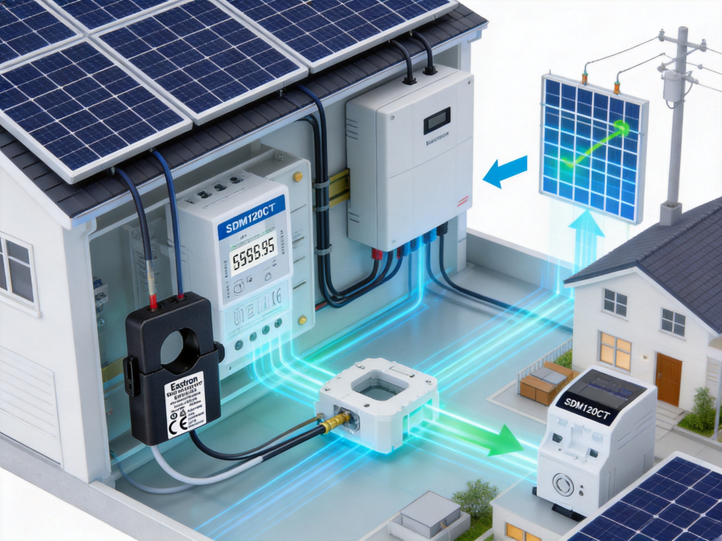
System designers can use the meter as a compact measurement component in inverter-control, energy-management, and monitoring architectures. The availability of pulse, Modbus, and M-Bus variants allows the same general metering platform to be adapted to different project requirements.
The range of measured parameters also reduces the need to specify several separate sensors. A designer can obtain energy, power, voltage, current, power factor, frequency, and reactive-energy data from one compact device, simplifying the bill of materials and data model.
Installers benefit from the one-module DIN-rail format and CT-based current measurement. The device can fit into compact enclosures and can be integrated into retrofit projects with limited panel space. Communication options also support integration with commonly used control and monitoring equipment.
Clear selection of the correct variant remains important. The installer should not substitute a 40 mA CT-input model for a 100 mA or 100 mV sensor application without confirmation. Matching the product to the actual sensor and controller requirements helps prevent commissioning delays.
End users gain better visibility into how electricity is generated, consumed, imported, and exported. This information can help identify inefficient operating schedules, unexpected loads, power-factor problems, and periods of unused solar generation.
In a zero-export installation, accurate measurement supports compliance with the site’s operating strategy. In a broader energy-management program, the data can be used to evaluate the success of efficiency improvements, battery storage, demand response, and load shifting.
Commercial and industrial electrical cabinets can expose measurement devices to electrical noise, temperature variation, vibration, and frequent switching events. A meter intended for these environments must be designed and tested with these conditions in mind.
The manufacturer’s EMC and environmental testing capability supports the development of products for such applications. Testing does not remove the need for proper installation, but it provides evidence that the design has been evaluated against relevant operating stresses.
Reliability also depends on firmware stability and communication behavior. A meter that maintains predictable register values, response timing, and configuration settings is easier to integrate into a long-term monitoring system. Stable communication reduces the risk of missing data and unnecessary service visits.
For installations with many meters, consistent production quality is essential. Devices must provide comparable measurement behavior so that data from different locations can be analyzed meaningfully. A structured quality-management system and controlled calibration process help support that consistency.
Metering should not be viewed only as a compliance function. Continuous energy data can reveal patterns that are not visible during a single inspection. A site may discover that its largest loads operate during periods of low solar production, that an inverter is frequently curtailed, or that reactive demand increases at particular times of day.
Power factor data can support the investigation of motor loads, transformers, HVAC systems, and other equipment. Frequency data can provide an additional indication of supply conditions. Voltage trends may identify issues related to long cable runs, overloaded circuits, or local grid conditions.
Import and export energy values can be compared with inverter production data. Differences between the two may represent on-site consumption, losses, curtailment, or measurement-location effects. A well-designed monitoring system can use these values to improve system understanding and identify maintenance opportunities.
When the meter is connected to a gateway or cloud platform, data can be archived for trend analysis. Historical records support comparisons across days, months, seasons, and operating conditions. They can also help verify the financial performance of a solar PV project.
Before ordering or installing the product, the following points should be reviewed:
• Confirm that the electrical system is single-phase 1P2W.
• Confirm the nominal voltage and acceptable operating-voltage range.
• Select the correct 40 mA CT-operated version or an approved alternative input version.
• Verify the CT ratio, output signal, polarity, and insulation characteristics.
• Determine whether two pulse outputs, RS485 Modbus, or M-Bus communication is required.
• Check compatibility with the inverter controller, gateway, PLC, or building-management system.
• Confirm the required active- and reactive-energy accuracy class.
• Check available DIN-rail space and enclosure conditions.
• Review local electrical codes and metering regulations.
• Plan commissioning tests for both import and export conditions.
• Confirm the product ordering code and technical documentation for the exact variant.
The meter is designed for a single-phase, two-wire AC system, identified as 1P2W. It is intended for applications such as solar PV metering, zero-export control, energy monitoring, and sub-metering.
Bidirectional measurement means that the meter can measure energy flowing in both directions. It can distinguish electricity imported from the grid from electricity exported toward the grid, which is essential for photovoltaic and zero-export applications.
The 40 mA CT input allows the meter to receive a low-level current signal from a compatible current transformer. The CT measures the primary circuit current while the meter processes the sensor signal. The exact CT ratio and sensor characteristics must match the selected meter variant.
No. The current transformer must be compatible with the meter’s input type and specification. The project engineer should confirm the CT output, ratio, polarity, burden, insulation, and wiring requirements before installation.
Yes. Reactive energy measurement is specified to IEC 62053-23 Class 2 and IEC 61557-12 Class 2 for the stated product configuration.
Depending on the selected version, the meter can provide RS485 Modbus RTU or M-Bus communication according to EN 13757-3. A pulse-output version is also available for applications that require discrete energy pulses.
The product information specifies two pulse outputs. These can be used for imported and exported energy or for other configured energy-pulse functions supported by the selected model.
It is designed for solar PV and zero-export metering applications. However, the complete system must also include a compatible controller or inverter, correct CT placement, appropriate communication settings, and proper commissioning.
The meter is designed as a one-module DIN-rail device with an approximate width of 18 mm. This compact format is useful in crowded distribution boards and inverter cabinets.
The stated rated voltage is 230 V, with an operational range of 80% to 120% of the rated voltage. The actual installation must be checked against the product documentation and local system conditions.
Yes. The multifunction design includes voltage, current, active power, power factor, frequency, active energy, reactive energy, and related values.
The installer should check CT orientation, CT wiring polarity, voltage-reference wiring, configuration, and the interpretation used by the monitoring software. A reversed sensor direction is a common cause of inverted energy-flow readings.
The described product is a single-phase 1P2W meter. A three-phase installation requires a suitable three-phase meter or an approved multi-meter arrangement. The product should not be applied outside its specified system configuration.
The manufacturer maintains professional testing capabilities for EMC, low-voltage, accuracy, and environmental evaluation. It also operates an ISO 9001 quality-management system and develops electricity meters, current sensors, communication modules, and energy-management products.
Yes. The product family includes different input and communication configurations. The buyer should confirm the ordering code, current-input type, pulse function, communication interface, certification, and regional requirements for the intended project.
The SDM120CT 40mA combines compact construction with the measurement and communication functions required by modern single-phase solar PV systems. Its one-module DIN-rail format helps conserve cabinet space, while CT operation provides flexible current measurement for suitable circuits.
Bidirectional active-energy measurement makes the meter suitable for photovoltaic generation and zero-export applications. Measurement of voltage, current, power, reactive energy, power factor, frequency, and demand-related values gives operators more information than a conventional energy counter. Two pulse outputs, RS485 Modbus RTU, and M-Bus options support integration with a broad range of control and monitoring systems.
The product’s value is strengthened by the manufacturer’s specialist experience in electricity measurement, in-house testing capabilities, international engineering resources, ISO 9001 quality management, and ongoing investment in hardware and software development. These strengths support a product approach focused not only on basic measurement but also on repeatability, communication, system integration, and long-term service.
For designers and installers, the most important success factors are correct variant selection, compatible CT specification, accurate sensor placement, suitable communication settings, and complete commissioning. When these factors are addressed, the meter can provide a practical and scalable foundation for solar monitoring, zero-export control, energy management, and compact low-voltage measurement systems.
IEC 62053-21, Electricity Metering Equipment — Particular Requirements — Static Meters for Active Energy.
IEC 62053-23, Electricity Metering Equipment — Particular Requirements — Static Meters for Reactive Energy.
EN 50470-1 and EN 50470-3, Electricity Metering Equipment — General Requirements and Particular Requirements for Static Meters.
IEC 61557-12, Electrical Safety in Low-Voltage Distribution Systems — Devices for Testing, Measuring, or Monitoring Protective Measures.
EN 13757-3, Communication Systems for Meters and Remote Reading of Meters — Application Layer Protocol.
Modbus Application Protocol Specification, Modbus Organization.
ISO 9001, Quality Management Systems — Requirements.
Manufacturer technical information for the SDM120CT 40mA single-phase multifunction energy meter.
Your email address will not be published. Required fields are marked *

We develop and produce high performance electricity meters, power analyzers, current sensors, communication modules and management systems.
Address:NO. 52, Dongjin Road, Nanhu, Jiaxing, Zhejiang, China
Copyright @ Eastron Electronic Co., Ltd. All rights reserved
