

 English
 Español
 Deutsch
 中文简体


Product Consultation
Your email address will not be published. Required fields are marked *
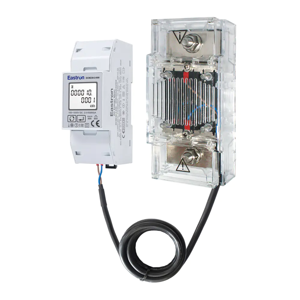
Max. Current 600A Modbus Multi-function DC Energy Meter for EV Charging Metering
Aug 02,2022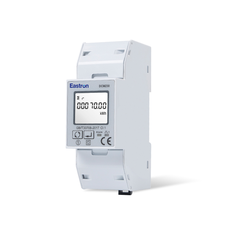
Din Rail DC Energy Monitoring Meter for EV Charging Metering
Aug 02,2022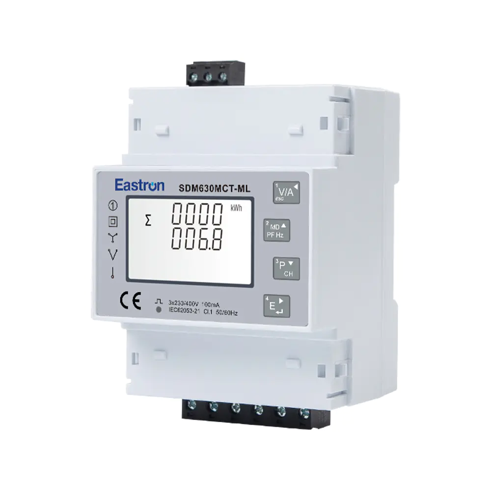
Multi-Circuit Three Phase Ethernet Modbus TCP Energy Meter for Data Center Metering
Aug 03,2022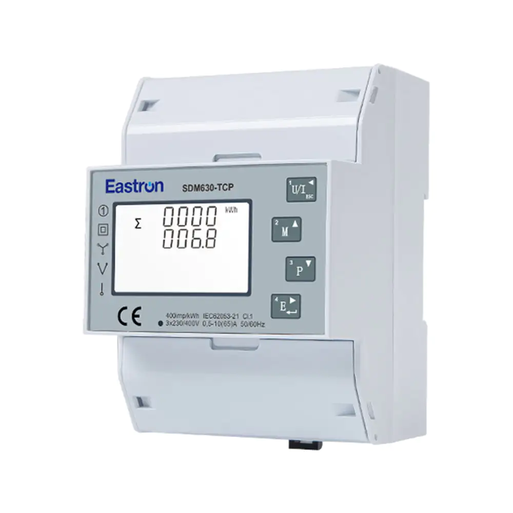
Direct Type Three Phase Ethernet Modbus TCP Energy Meter for Data Center Metering
Nov 24,2022
RS485 CT Connection Three Phase Din Rail Energy Meter for PV Metering
May 30,2025
CT Type Three Phase Din Rail Wifi Energy Meter for PV Metering
May 30,2025Content
Reliable current measurement is fundamental to modern electrical monitoring. From industrial distribution boards and commercial buildings to energy management systems and power quality installations, measurement equipment must receive a stable and accurate current signal. A current transformer, or CT, provides this interface by converting a high primary current into a lower, standardized secondary current that can be safely connected to meters, power analyzers, protection devices, and monitoring systems.
The ESCT-ABO 5A CT output solid-core current sensor is designed for applications that require dependable current transformation, convenient installation, and long-term identification of installed components. It is part of a broad current transformer range developed for electricity metering and energy measurement systems. The series combines a solid-core construction with a practical plastic enclosure, snap-on body design, built-in covers, multiple mounting methods, and a choice of accuracy classes.
Available primary current ratings extend from 5A to 3000A across eight frame sizes. The product is suitable for installations that use a 5A secondary signal and require current measurement for metering, monitoring, load analysis, or system control. Selected models can achieve accuracy up to Class 0.2S, while more general-purpose options are available in Classes 3, 1, 0.5, 0.5S, 0.2, and 0.2S.
This article explains the product’s structure, operating characteristics, available ratings, installation benefits, manufacturing strengths, and typical applications. It also compares the practical advantages of the series with common alternatives and provides selection guidance for engineers, panel builders, system integrators, contractors, and energy management professionals.
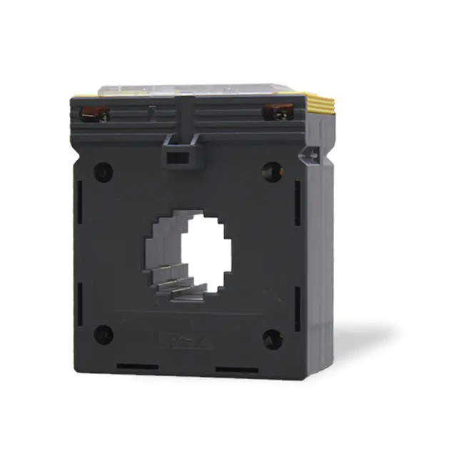
ESCT-ABO 5A CT output Solid Core Current Sensor
A current transformer is an instrument transformer that reproduces the current flowing through a primary conductor at a reduced level on its secondary winding. In a conventional metering application, the primary circuit may carry hundreds or thousands of amperes, while the connected meter is designed to receive a much smaller current signal. The CT makes this measurement possible while helping isolate the measuring equipment from the high-current circuit.
A 5A-output CT produces a nominal secondary current of 5A when the primary current reaches the specified rated value. For example, a 500/5A CT is intended to provide approximately 5A on its secondary side when 500A flows through the primary conductor. A meter, analyzer, or relay connected to the secondary circuit can then calculate electrical current, power, energy, demand, and related parameters.
Standardized secondary outputs simplify the design of measurement systems. Many industrial meters, multifunction meters, power analyzers, and protection devices are available with 5A CT inputs. Using a standardized output also allows a panel builder to select different primary ratings while retaining compatibility with the same measurement platform.
Current transformers must be selected carefully. The primary rating, secondary output, accuracy class, burden, installation method, aperture size, insulation arrangement, and intended application all influence the performance of the complete system. A CT that is appropriate for general load monitoring may not be suitable for revenue metering or high-accuracy energy allocation. The ESCT-ABO range addresses this need by offering several accuracy classes and a wide selection of primary current ratings.
The ESCT-ABO series is a solid-core current transformer range with 1A or 5A output options. The product described here is the 5A-output version. It uses a fixed magnetic core and a molded plastic enclosure to create a compact measuring device for installation around a busbar or conductor.
The design is offered in eight frame sizes. These frame options accommodate primary current ratings from 5A to 3000A, depending on the selected model and configuration. The published table includes the ESCT-ABO-30, ESCT-ABO-40, ESCT-ABO-60, and ESCT-ABO-100 frame families, with a selection of primary ratings within each frame. The frame designation is associated with the physical size of the CT and its corresponding internal passage, while the exact mechanical dimensions should be confirmed from the applicable product drawing before installation.
The main features include:
The combination of a solid magnetic core and a molded enclosure makes the series suitable for permanent installations where the conductor or busbar can be routed through the CT opening during assembly. Unlike split-core transformers, the solid-core construction is not intended to be opened around an energized conductor. It is therefore commonly selected for new switchboards, factory-built distribution panels, and installations where the conductor can be disconnected during the original assembly process.
A solid-core CT uses a continuous magnetic circuit. The primary conductor passes through the central opening, and the magnetic core remains mechanically closed during normal operation. This construction offers several important benefits for fixed electrical installations.
First, a continuous core can support stable magnetic performance because there is no hinged core joint or removable mating surface in the magnetic path. In a split-core design, the accuracy and repeatability of the measurement can be affected by the condition, alignment, and closure of the core interface. A solid-core design avoids that particular source of variation when it is correctly installed.
Second, the solid-core format is often compact and mechanically robust. It can be integrated into a panel layout with a fixed orientation and a defined mounting position. This is valuable in switchboards where current transformers must remain aligned with busbars, phase conductors, terminal blocks, or metering compartments.
Third, solid-core CTs can be cost-effective for original equipment manufacturers and panel builders. When the CT is installed during assembly, the absence of a split or hinged core can simplify the component structure and reduce the number of mechanical parts. It also supports consistent factory installation and testing.
The trade-off is that a solid-core CT generally requires the primary conductor to be disconnected or inserted during panel construction. For retrofit work on live or difficult-to-access cables, a split-core or flexible current sensor may be more convenient. The correct choice depends on the installation stage, safety procedure, conductor geometry, required accuracy, and available space.
The ESCT-ABO series provides two fixing methods. The three-side base arrangement enables the CT to be secured to a suitable mounting surface. This method is useful in switchboards, control cabinets, metering panels, and equipment assemblies where the transformer needs a stable, repeatable position.
Busbar mounting provides an alternative approach. The CT can be positioned around the busbar and secured as part of the busbar arrangement, subject to the applicable mechanical design and installation instructions. This can help reduce the need for additional brackets and may support a cleaner internal panel layout.
Multiple mounting methods provide practical advantages over products limited to a single fixing arrangement. Panel manufacturers can adapt the same basic CT family to different cabinet designs, reducing the need to qualify several unrelated components. System integrators can also use the frame size and mounting method that best fits the available space.
Correct mechanical installation remains essential. The primary conductor should be centered as far as practical within the CT opening, and the CT should not be subjected to excessive mechanical stress from busbars, cables, or unsupported conductors. The transformer should be fixed securely so that vibration, cable movement, and maintenance activity do not change its position or damage its terminals.
Before ordering, the installer should verify the frame size, opening dimensions, fixing-hole arrangement, insulation clearances, busbar dimensions, and terminal orientation. Product drawings should be used for final mechanical design because the available information identifies the frame families but does not provide all dimensional values in the specification summary.
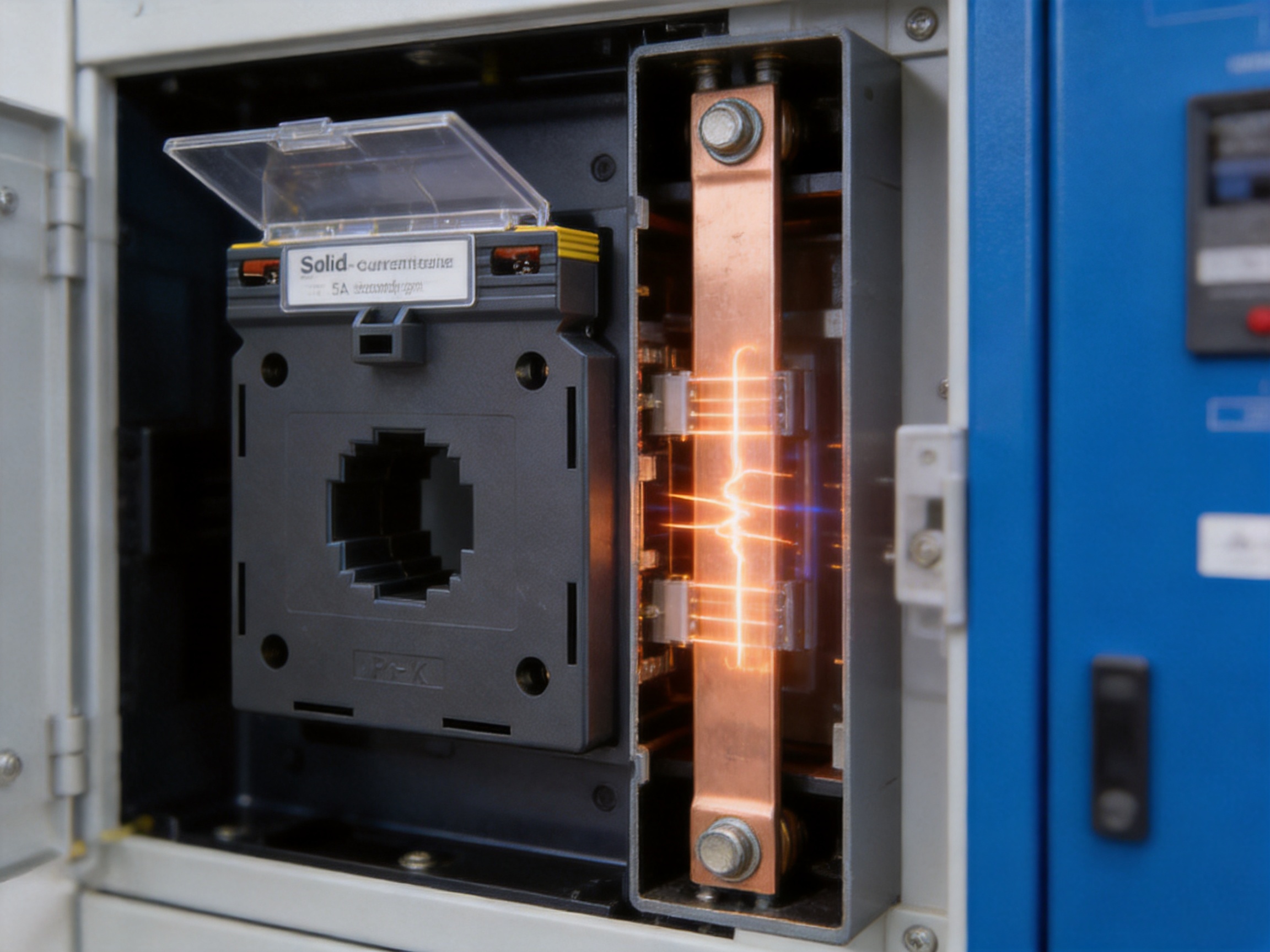
The ESCT-ABO design incorporates a hinged terminal cover. A terminal cover helps protect the secondary connection area from accidental contact and reduces the possibility of unintentional interference after commissioning. It also contributes to a more organized panel interior by enclosing the connection point in a defined protective area.
CT secondary circuits require special attention during installation and maintenance. A current transformer secondary should not normally be left open while current is flowing in the primary circuit. An open secondary can produce a dangerously high voltage and may damage the transformer or connected equipment. Proper shorting, isolation, and maintenance procedures must always be followed in accordance with applicable electrical safety requirements.
The terminal cover does not replace safe working practices, but it provides a physical layer of protection and helps preserve the intended wiring arrangement. It can also reduce the risk of accidental contact during routine inspection of adjacent equipment.
A transparent cover for the name plate is another practical feature. Electrical panels often contain many similar-looking transformers, particularly where several phases, feeders, or outgoing circuits are installed together. A protected name plate allows the device to remain identifiable after long-term service, cleaning, vibration, or maintenance work.
Identification can include the CT model, primary and secondary ratings, accuracy class, burden, phase designation, circuit reference, installation date, or other project information. The transparent cover helps protect this information while keeping it visible. This is particularly useful in energy management systems, multi-tenant buildings, industrial plants, and metering installations where correct circuit identification affects billing, troubleshooting, and maintenance efficiency.
The lead-seal hole design further supports controlled access and anti-tampering practices. In applications involving energy allocation or formal meter verification, a sealable arrangement can help indicate whether the protected area has been opened. The exact sealing procedure depends on the project owner, metering authority, local regulations, and applicable certification requirements.
Accuracy class describes the permitted measurement error under specified operating conditions. The required accuracy depends on the purpose of the measurement. A basic load-monitoring system may not require the same performance as a revenue meter, submetering system, or high-precision energy allocation installation.
The series supports a wide range of accuracy classes: Class 3, Class 1, Class 0.5, Class 0.5S, Class 0.2, and Class 0.2S. The lower the class number, the tighter the stated accuracy requirement generally is. Special classes such as 0.5S and 0.2S are commonly associated with improved accuracy over a wider current range, subject to the relevant standard and test conditions.
Class 3 and Class 1 options may be suitable for general indication, equipment monitoring, and less demanding control applications. Class 0.5 and Class 0.5S options are appropriate where improved measurement accuracy is needed for energy monitoring, internal cost allocation, or more precise power management.
Class 0.2 and Class 0.2S options are intended for applications where a higher level of measurement accuracy is required. Such applications may include advanced energy management, high-value load monitoring, system verification, or metering arrangements designed around precise current measurement. The final suitability must be confirmed against the complete meter system, applicable standards, test conditions, and project requirements.
Accuracy is not determined by the CT alone. The meter input, cable resistance, secondary lead length, burden, power factor, primary current level, frequency, temperature, installation position, and magnetic environment can all influence the result. A high-accuracy CT connected to an unsuitable meter or overloaded secondary circuit will not deliver the expected system performance.
Burden is the load connected to the secondary circuit of a current transformer, normally expressed in volt-amperes. It includes the input burden of the connected meter or relay and the impedance of the secondary wiring. The CT must be selected so that its rated burden is compatible with the actual secondary circuit.
The published ESCT-ABO data lists burden values such as 1.5VA, 2.5VA, 3.75VA, 5VA, 7.5VA, 10VA, and 15VA, depending on the frame, primary rating, and accuracy class. These values provide a basis for system design, but the engineer should calculate the actual connected burden before final selection.
Long secondary cables increase circuit resistance. If the cable run is long or the conductor cross-section is too small, the resulting burden may exceed the CT rating. Excessive burden can affect accuracy and may cause the transformer to perform outside its specified conditions. For this reason, secondary wiring should be kept as short as practical, sized appropriately, and routed in a way that protects it from mechanical damage and excessive electromagnetic interference.
When a CT is connected to an energy meter or power analyzer, the total burden should include the meter input and all wiring connections. Terminal blocks, test switches, fuses, and additional devices may also contribute to the circuit load. Careful calculation is especially important for Class 0.2, Class 0.2S, Class 0.5, and Class 0.5S installations.
| Frame family | Typical listed primary current range | Secondary output | Published burden range | Typical application direction |
|---|---|---|---|---|
| ESCT-ABO-30 | 50A to 300A | 5A | 1.5VA to 5VA | Small and medium distribution circuits |
| ESCT-ABO-40 | 75A to 500A | 5A | 1.5VA to 5VA | Commercial and industrial feeders |
| ESCT-ABO-60 | 200A to 1000A | 5A | 5VA to 10VA | Large feeders and busbar systems |
| ESCT-ABO-100 | 800A to 3000A | 5A | 5VA to 15VA | High-current switchboards and industrial systems |
The table summarizes the listed product data. It is not a substitute for the detailed technical schedule or dimensional drawing. Where an application requires a particular accuracy class, burden, or certification, the exact ordering code and technical documentation should be reviewed before purchase.
Choosing the correct primary current rating is one of the most important steps in CT selection. The rating should reflect the expected operating current and the characteristics of the monitored circuit. A CT that is significantly oversized may provide less useful resolution at normal operating load, while a CT that is undersized may saturate or operate outside its intended range during normal or peak conditions.
The ESCT-ABO range includes primary ratings such as 50A, 60A, 75A, 100A, 150A, 200A, 250A, 300A, 400A, 500A, 600A, 750A, 800A, 1000A, 1200A, 1500A, 1600A, 2000A, 2500A, and 3000A. Availability depends on the frame family.
For a circuit with a stable operating current near its design load, the CT primary rating is often selected close to the expected maximum continuous current. For a circuit with significant starting current, intermittent overload, or future expansion, the selection should account for those conditions. The engineer should also consider whether the CT will be used for demand measurement, protective control, energy allocation, or general indication.
For example, a 200A feeder may be paired with a 200/5A CT when the circuit load is expected to remain close to that value. A 500A industrial feeder may use a 500/5A unit, while a larger switchboard busbar may require a 1000/5A, 1600/5A, or 3000/5A configuration. The correct selection depends on the actual conductor rating, expected load profile, meter input, and project specifications.
The primary current value must match the meter configuration. If the CT ratio is entered incorrectly in the meter, the displayed current, power, energy, and demand values will be inaccurate even if the transformer itself is performing correctly. Ratio settings should therefore be checked during commissioning and recorded in the panel documentation.
The ESCT-ABO-30 family includes 50A, 60A, 75A, 100A, 150A, 200A, 250A, and 300A primary options, all listed with a 5A secondary output. Depending on the selected primary rating, the published burden values include 1.5VA, 2.5VA, 3.75VA, and 5VA for the stated Class 0.5 and Class 1.0 columns.
The ESCT-ABO-40 family includes primary ratings from 75A through 500A. Listed options include 75A, 100A, 150A, 200A, 250A, 300A, 400A, and 500A. The published burden values range from 1.5VA to 5VA in the stated table.
The ESCT-ABO-60 family is intended for higher current levels. Listed primary options include 200A, 250A, 300A, 400A, 500A, 600A, 750A, 800A, and 1000A. The published burden increases from 5VA for several ratings to 10VA for the higher current options.
The ESCT-ABO-100 family covers 800A to 3000A. Listed options include 800A, 1000A, 1200A, 1500A, 1600A, 2000A, 2500A, and 3000A. The stated burden values range from 5VA to 15VA, with larger burden values provided for higher primary ratings and the listed accuracy conditions.
These configurations give panel builders a practical range of choices without requiring a different product concept for each current level. The frame can be selected according to the conductor or busbar arrangement, while the primary rating can be selected according to the circuit requirements.
The most suitable CT depends on the installation. Nevertheless, the ESCT-ABO series offers several practical advantages compared with basic fixed-core CTs that provide only one mounting method or limited identification features.
Some conventional CTs are designed only for a specific bracket or busbar arrangement. The two fixing methods of the ESCT-ABO series support greater flexibility in panel construction. A three-side base can be used where the CT must be secured to a panel surface, while busbar mounting can be used where the busbar arrangement provides the most practical support.
A basic transformer may have a printed label that becomes difficult to read after years of service. The transparent name-plate cover helps preserve important identification data and makes inspection more efficient. This is an advantage in facilities with many current transformers and complex metering systems.
The built-in hinged terminal cover provides a defined enclosure around the secondary terminals. This is more convenient than relying solely on a separate external cover or improvised protective arrangement. It can help maintain a cleaner installation and reduce accidental interference during panel maintenance.
Some entry-level CT ranges are available only in a general-purpose accuracy class. The ESCT-ABO range provides options extending to Class 0.2S, allowing the same product family to serve basic monitoring and more demanding measurement applications. This simplifies product evaluation for manufacturers serving several types of electrical project.
The availability of primary ratings from 5A to 3000A means that the series can be applied across small feeders, commercial distribution systems, industrial panels, and high-current switchboards. A broad range can reduce the need to combine products from multiple suppliers, provided that the selected model meets the required dimensions and electrical specifications.
The solid-core construction and snap-on body are well suited to new panel production. A manufacturer can integrate the CT into a standardized assembly process, perform wiring and testing before shipment, and document the transformer ratio as part of the completed system.
These advantages do not mean that a solid-core CT is always superior to a split-core, flexible, or specialty protection CT. Retrofit projects may require an openable design, and protection applications may require different excitation and saturation characteristics. The strength of the ESCT-ABO series is its fit for fixed, metering-oriented installations where mechanical stability, accuracy, identification, and repeatable assembly are important.
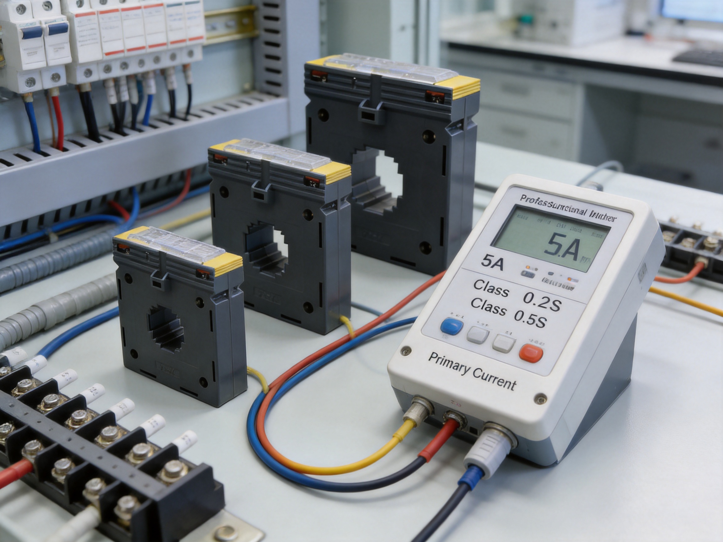
The product is manufactured by Eastron Electronic Co., Ltd., a company focused on electricity meters, power analyzers, current sensors, communication modules, and energy measurement solutions. Its product development and manufacturing activities are supported by engineering teams in China and the United Kingdom, together with cooperation involving universities and technical institutions.
A current transformer is a precision electrical component. Its performance depends on core material, winding consistency, insulation construction, enclosure molding, terminal assembly, mechanical dimensions, and final testing. A manufacturer with experience across meters, analyzers, and current sensors can design the CT with a better understanding of how it will be used in a complete measurement system.
The company operates a professional laboratory capable of performing EMC, LVD, accuracy, and environmental tests according to IEC, EN, GB, and UL-related requirements. These testing capabilities are important because an energy measurement product must perform reliably not only under nominal electrical conditions but also in the presence of electromagnetic disturbance, temperature variation, and other environmental influences.
Accuracy testing verifies the relationship between primary current and secondary output under defined conditions. Environmental testing helps assess performance across the intended operating conditions. EMC testing evaluates resistance to electromagnetic disturbance and the possibility of unwanted emissions. LVD-related testing supports assessment of electrical safety and insulation requirements. Together, these capabilities create a more complete product verification process than a simple output check.
The company follows the ISO 9001 quality management system. A structured quality system can support controlled documentation, supplier management, production traceability, inspection procedures, corrective action, and continuous improvement. These processes are particularly valuable for CTs because small variations in materials, winding, assembly, or terminal connections can influence accuracy and reliability.
Production approved by SGS according to MID standards is also relevant to customers working on regulated metering projects. The exact certification or approval status must always be confirmed for the specific product variant and intended market. However, experience with metering-related requirements demonstrates an understanding of controlled measurement applications and formal verification expectations.
In addition to manufacturing, the company holds patented technologies in software, embedded software, and hardware and has been recognized as a high-tech enterprise and a high-tech research and development center for electricity application. These capabilities support a broader system perspective. The CT can be used alongside the company’s electricity meters, power analyzers, communication products, and management systems to create a coordinated energy measurement solution.
High-quality CT production begins with consistent raw materials. Core material selection affects magnetic performance, losses, linearity, and accuracy. Winding material and insulation components must be appropriate for the electrical and thermal requirements. The plastic enclosure must provide mechanical strength, dimensional stability, and suitable protection for the internal components.
During assembly, the winding must be positioned consistently, terminals must be correctly connected, and the enclosure must be properly closed. A snap-on body can support efficient assembly, but it must be manufactured with controlled tolerances so that the components remain secure throughout the product’s service life.
Final inspection should include verification of the ratio, polarity, insulation, appearance, terminal integrity, and relevant accuracy parameters. Where required by the product specification, samples or finished units may undergo environmental, dielectric, EMC, and accuracy testing. The manufacturer’s laboratory capabilities provide an internal resource for this type of product validation.
Traceability is also important. A clearly identified model, primary rating, secondary output, accuracy class, and burden helps link the installed product to its technical record. The transparent name-plate cover reinforces this benefit during field inspection.
For customers purchasing CTs in volume, quality documentation may include inspection reports, test certificates, certificates of conformity, manufacturing records, and project-specific documentation. The exact documents available depend on the order, market, certification requirement, and product variant.
Industrial facilities often contain multiple feeders supplying motors, heating systems, compressors, pumps, production lines, and auxiliary equipment. CTs installed on these feeders provide current signals to multifunction meters or energy management systems. The resulting data can be used to track demand, identify abnormal loading, compare production areas, and support energy reduction programs.
Office buildings, retail facilities, hotels, hospitals, and educational campuses use current transformers for main incomers, tenant substations, HVAC systems, lighting distribution, and critical services. Accurate submetering can support cost allocation and help facility managers understand where energy is being consumed.
Switchboards and motor control centers require organized internal layouts and dependable component identification. The ESCT-ABO mounting options, terminal cover, and transparent name-plate cover support installations where several CTs are placed close together and must remain easy to service.
Energy management systems use current and voltage measurements to calculate active power, reactive power, apparent power, power factor, energy consumption, and demand. A 5A-output CT can be paired with compatible meters, gateways, and analyzers to provide the current input required by the system.
Solar power plants, battery energy storage systems, and hybrid energy installations need measurement at grid connection points, inverters, battery converters, and auxiliary circuits. The current rating and accuracy class must be selected according to the system architecture and measurement purpose. The solid-core design is particularly suitable for new assemblies where the conductor layout is planned before commissioning.
In multi-tenant buildings and industrial parks, separate measurement may be used to allocate energy costs among tenants, departments, production lines, or operating areas. A CT with a suitable accuracy class, protected identification, and sealable design can support the organization of these metering points. Local regulations and project requirements determine whether additional certification is necessary.
Installation should be carried out by qualified electrical personnel using the applicable national and local safety procedures. The circuit must be de-energized when required, and the installer must confirm that the CT rating and physical size match the conductor or busbar.
The primary conductor should pass through the CT in the correct direction. Current transformers are polarized devices, and the orientation of the primary conductor affects the phase relationship between primary and secondary current. The polarity markings should be followed, and the orientation should be consistent across all phases.
Each CT should be matched to the correct phase and meter input. Phase identification should be recorded clearly. The secondary terminals should be wired according to the meter or analyzer connection diagram, with attention to polarity and terminal designations.
The secondary circuit should never be casually disconnected while the primary circuit is energized. Before removing a meter, test link, or secondary conductor, the CT secondary should be shorted or isolated using an approved procedure. This requirement is central to safe CT maintenance.
After installation, the commissioning process should verify:
A commissioning record should include the CT model, frame size, ratio, accuracy class, burden, phase designation, installation location, and date. This information simplifies future troubleshooting and replacement.
Selection begins with the primary circuit. Determine the normal operating current, maximum continuous current, expected starting current, and possible future expansion. Then select a primary rating that provides useful measurement over the expected operating range without creating an avoidable risk of overload.
Next, confirm the secondary input of the connected device. This article focuses on the 5A-output configuration, but the series also includes 1A output options. A meter designed for a 1A CT input must not be connected as though it were a 5A device. The output type must match the meter configuration and the complete secondary circuit.
The physical arrangement is equally important. Measure the busbar width, height, spacing, cable diameter, insulation thickness, and available clearance. Select a frame with a suitable opening and fixing method. The CT must fit without forcing the conductor or compromising required insulation distances.
Choose the accuracy class according to the measurement objective. General monitoring may use a less demanding class, while energy allocation and precision metering may require Class 0.5S, Class 0.2, or Class 0.2S. Confirm the applicable accuracy standard and operating range before finalizing the order.
Calculate the secondary burden. Include the meter input, secondary cable resistance, terminal blocks, test devices, and any other connected equipment. The calculated burden should remain within the selected CT’s rated value under the specified conditions.
Finally, review environmental conditions. Temperature, humidity, vibration, enclosure location, altitude, pollution level, and electromagnetic environment may influence the product selection. The manufacturer’s technical documentation should be consulted for detailed operating limits and certification information.
Large electrical systems may contain dozens or hundreds of CTs. If the identification of each device becomes unclear, maintenance teams may spend considerable time tracing circuits. Incorrect identification can also lead to incorrect meter ratio settings, phase mismatches, or inaccurate energy reports.
The transparent name-plate cover helps preserve the product’s identity. A maintenance engineer can inspect the model and rating without removing the cover, provided the panel design allows safe visual access. A protected name plate is especially useful when the CT is installed in a compact metering compartment where labels may be exposed to dust, vibration, or repeated service activity.
Identification should be supported by a complete panel schedule. The label on the CT should correspond to the electrical drawing, meter channel, feeder designation, and energy management software configuration. This approach creates consistency from the physical installation through to the digital monitoring system.
The lead-seal hole can also support controlled access. When a project requires evidence that a metering component has not been altered, an approved seal can be applied according to the responsible authority’s procedure. The feature is therefore relevant to applications where measurement integrity and controlled maintenance are important.
A CT is one part of a measurement chain. The complete system may include voltage transformers or direct voltage inputs, a multifunction energy meter, a power analyzer, communication gateways, data servers, dashboards, and control software. The quality of the final result depends on compatibility and correct configuration across all these components.
Eastron’s broader product portfolio includes electricity meters, smart meters, power analyzers, current sensors, communication modules, and management systems. This portfolio allows customers to source related measurement products from a company with experience in the wider energy monitoring field.
When the CT is paired with a compatible meter, the system can measure current and calculate electrical parameters in real time. A gateway can then transmit the data to a building management system, industrial control platform, or cloud-based monitoring environment. Operators can use the information to identify peak demand, compare loads, detect unusual consumption, and evaluate energy-saving measures.
System integration also requires attention to communication and data quality. The CT ratio must be configured correctly, phase relationships must be preserved, and the measurement channels must be mapped accurately. The use of a clearly labeled CT with a consistent product family can make commissioning and system expansion more manageable.
Electrical equipment supplied to international markets must address differences in standards, installation practices, documentation, and certification expectations. Eastron’s laboratory experience with IEC, EN, GB, and UL-related testing supports the development and evaluation of products for multiple regions.
The company’s location in Jiaxing, Zhejiang, near major commercial and industrial centers including Shanghai and Hangzhou, provides access to manufacturing resources, engineering talent, logistics infrastructure, and supply chain partners. Its products and services have been supplied to customers in more than 50 countries across Europe, Asia-Pacific, the Americas, the Middle East, and Africa.
International supply also requires more than manufacturing capacity. Customers need technical support, product selection assistance, documentation, after-sales service, and communication with project teams. The company maintains professional technical and after-sales teams to support these requirements.
For distributors and system integrators, a broad product family can simplify stock management and customer support. For original equipment manufacturers, repeatable product formats and multiple ratings can support standard panel designs. For end users, a traceable product from an established measurement supplier can improve confidence in long-term support.
The ESCT-ABO series should be selected for applications that match its solid-core construction and metering-oriented characteristics. It is not automatically the best choice for every current measurement situation.
For retrofit work where conductors cannot be disconnected, a split-core CT may offer easier installation. For temporary measurements or very large flexible conductors, a flexible Rogowski coil may be more practical. For high-speed protection systems, a dedicated protection-class CT may be required. For low-current electronic monitoring, a sensor with a voltage output or a specialized low-power design may be more suitable.
Similarly, a 5A-output CT should be used only with equipment designed for a 5A secondary input. The installer must not assume that all meters accept both 1A and 5A signals. The selected product must also meet the required burden, accuracy, insulation, environmental, and certification conditions.
These considerations are not weaknesses of the product. They are part of responsible engineering selection. A current transformer performs well when its electrical and mechanical characteristics match the application.
Current transformers normally require limited maintenance when installed correctly. Periodic inspection should nevertheless be included in the facility maintenance program. The technician can check the enclosure, fixing points, terminal cover, name-plate visibility, wiring condition, and signs of overheating or mechanical stress.
Secondary terminals should be inspected for secure connections and evidence of discoloration. Loose connections can increase resistance and produce heat. The primary conductor should remain properly supported so that its weight or vibration does not transfer excessive force to the CT.
Identification should be reviewed after modifications to the switchboard or energy management system. If a feeder is renamed, a meter channel is reassigned, or a CT is replaced, the physical label and digital configuration should be updated together.
Testing should be performed according to the facility’s procedures and the requirements of the applicable standards. Any test involving the secondary circuit must account for the safety risks associated with an energized primary circuit. Qualified personnel should use appropriate shorting and test equipment.
The built-in covers and protected labeling features support long-term serviceability. They do not eliminate the need for inspection, but they help preserve the integrity and clarity of the installation over time.
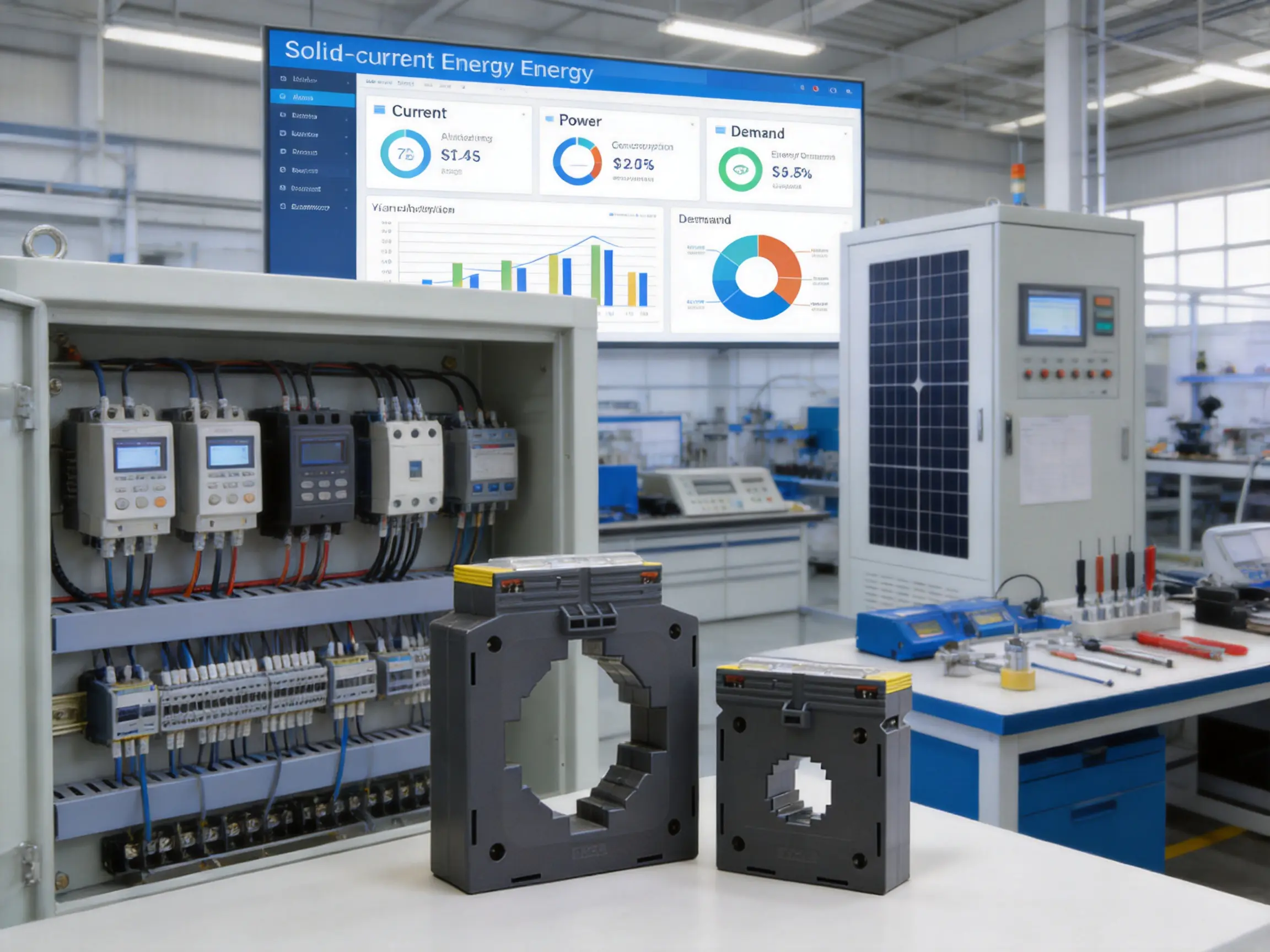
Panel builders need components that are mechanically consistent, electrically documented, and easy to integrate into repeatable designs. The ESCT-ABO series addresses these needs through multiple frame sizes, standardized 5A output, alternative mounting methods, and a broad accuracy selection.
A panel manufacturer can design a family of distribution boards using different CT ratings while retaining a familiar installation approach. This can reduce engineering time and simplify operator training. The snap-on body and built-in covers also support a neat assembly process.
System integrators benefit from the product’s compatibility with energy meters and power analyzers that use conventional CT inputs. The wide range of primary ratings allows measurement points to be designed around actual feeder capacities. Where high-accuracy monitoring is required, the availability of Class 0.2S or Class 0.5S options can reduce the need to search for a separate specialized supplier.
For project managers, product consistency can help simplify procurement and documentation. A single supplier capable of providing current transformers, meters, analyzers, gateways, and energy management products may reduce coordination between different manufacturers. Technical support can also be more direct when related components come from the same measurement technology provider.
Consider an industrial facility with a main incoming switchboard rated for 1000A, several 400A production feeders, and smaller 100A auxiliary feeders. The facility wants to measure current, power, and energy on each circuit using 5A-input meters.
The main incoming circuit may require an ESCT-ABO-60 or ESCT-ABO-100 configuration, depending on the busbar dimensions, required primary rating, and available space. A 1000/5A option would be considered if the expected maximum load is close to 1000A. The 400A feeders may use an ESCT-ABO-40 configuration, while the 100A auxiliary feeders may use an ESCT-ABO-30 or ESCT-ABO-40 configuration, subject to the conductor size and physical opening.
If the system is intended only for operational monitoring, a general-purpose accuracy class may be sufficient. If the facility intends to allocate energy costs between production departments, a higher accuracy class may be selected. The engineering team must then calculate the secondary burden, verify the meter input, and confirm the installation dimensions.
Each CT would be labeled according to its feeder and phase. The meter configuration would include the correct ratio, and the commissioning team would verify phase sequence and power direction. The resulting data could be transmitted through gateways to an energy management platform for trend analysis and reporting.
This example shows how a broad CT family can support a complete facility measurement plan while maintaining a consistent installation and documentation method.
Electrical panels may be installed in environments with temperature changes, dust, humidity, vibration, and electromagnetic interference. The CT enclosure provides mechanical protection for the internal transformer assembly, while the product’s verification capabilities include environmental and EMC testing within the manufacturer’s laboratory activities.
Actual field performance depends on the enclosure, installation conditions, ventilation, conductor temperature, and surrounding equipment. The CT should be installed within the operating limits stated in the relevant documentation. It should not be exposed to conditions beyond its design rating without an engineering assessment.
Correct installation is also important for thermal performance. The primary conductor may generate heat at high current, and the CT should be positioned so that heat accumulation is controlled. Busbar joints, cable terminations, and nearby components should be inspected because excessive local temperature can affect the complete assembly.
Stable mechanical mounting helps resist vibration and movement. The two fixing methods allow the installer to choose an arrangement that supports the CT appropriately rather than leaving it suspended from the secondary wiring or forced against adjacent equipment.
A 5A-output current transformer converts a high primary current into a nominal 5A secondary signal for a compatible meter, power analyzer, relay, or monitoring device. The primary-to-secondary ratio must be configured correctly in the connected equipment.
No. The ESCT-ABO series is a solid-core current transformer. The primary conductor or busbar normally passes through the fixed opening during panel assembly. It is therefore especially suitable for new switchboards and factory-built electrical equipment.
The complete series covers primary currents from 5A to 3000A. The listed 5A-output configurations include frame families such as ESCT-ABO-30, ESCT-ABO-40, ESCT-ABO-60, and ESCT-ABO-100, with specific ratings assigned to each frame.
The product information identifies Classes 3, 1, 0.5, 0.5S, 0.2, and 0.2S. The correct class depends on whether the CT is used for general monitoring, energy management, internal allocation, precision measurement, or another defined purpose.
A 1A or 5A designation identifies the nominal secondary current at the rated primary current. The output must match the input specification of the connected meter or analyzer. A 1A-input meter and a 5A-input meter are not interchangeable without suitable equipment and configuration.
The selected burden should be greater than or equal to the actual burden of the complete secondary circuit under the specified operating conditions. The calculation should include the meter input, wiring resistance, terminal blocks, test switches, and other connected devices.
The solid-core design generally requires the conductor to be inserted through the opening during assembly. Installation and maintenance must follow qualified electrical safety procedures. The secondary circuit must not be opened while the primary circuit is energized.
The series supports three-side base fixing and busbar mounting. The appropriate method depends on the panel structure, conductor arrangement, available space, and mechanical support requirements.
It protects identification information while keeping the model, ratio, phase, or circuit reference visible. This helps maintenance teams identify similar CTs in large switchboards and supports accurate documentation.
Some configurations may be appropriate for demanding metering applications, including options with high accuracy classes. However, the exact product variant, applicable certification, installation method, meter system, and local regulations must be verified before use in revenue or legally controlled metering.
The manufacturer operates a professional laboratory capable of accuracy, EMC, LVD, and environmental testing according to IEC, EN, GB, and UL-related requirements. The exact tests and documentation available depend on the product and project requirements.
Useful information includes the primary current, required secondary output, accuracy class, burden, conductor or busbar dimensions, mounting preference, operating environment, quantity, destination market, and whether special certification or documentation is required.
The ESCT-ABO 5A CT output solid-core current sensor is designed for accurate and dependable current measurement in fixed electrical installations. Its solid-core structure supports stable factory-built assembly, while the two mounting methods provide flexibility for panel and busbar applications. The hinged terminal cover, transparent name-plate cover, and lead-seal hole address practical needs involving safety, identification, maintenance, and measurement integrity.
With primary current options extending from 5A to 3000A and accuracy classes reaching Class 0.2S, the series can serve a wide variety of energy measurement requirements. Its listed burden options support different secondary circuit designs, provided that the meter input and wiring are correctly calculated.
The product is strengthened by the manufacturer’s broader expertise in electricity meters, power analyzers, current sensors, communication modules, and energy management systems. Laboratory capabilities covering accuracy, EMC, LVD, and environmental testing, together with ISO 9001 quality management and international supply experience, support a structured approach to product reliability and application support.
For panel builders, contractors, system integrators, and facility operators, the main value of the series lies in its balance of electrical performance, mechanical practicality, product identification, and application range. Proper selection and installation remain essential, but when matched to the project requirements, the ESCT-ABO series provides a dependable current measurement interface for modern energy monitoring systems.
1. Eastron Electronic Co., Ltd., ESCT-ABO Series Product Information and Technical Data.
2. International Electrotechnical Commission, Instrument Transformers and Current Transformer Performance Standards.
3. International Electrotechnical Commission, Electricity Metering Equipment and Accuracy Requirements.
4. ISO, Quality Management Systems Requirements, ISO 9001.
5. General engineering guidance for current transformer selection, secondary burden calculation, polarity verification, and safe maintenance procedures.
Your email address will not be published. Required fields are marked *

We develop and produce high performance electricity meters, power analyzers, current sensors, communication modules and management systems.
Address:NO. 52, Dongjin Road, Nanhu, Jiaxing, Zhejiang, China
Copyright @ Eastron Electronic Co., Ltd. All rights reserved
