

 English
 Español
 Deutsch
 中文简体


Product Consultation
Your email address will not be published. Required fields are marked *
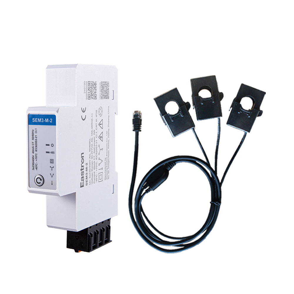
RS485 CT Connection Three Phase Din Rail Energy Meter for PV Metering
May 30,2025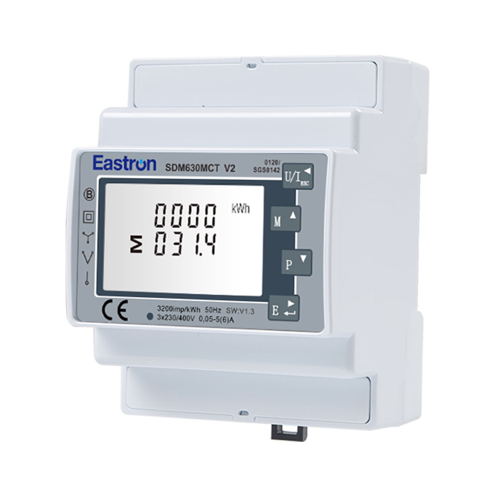
MID Approved CT Type Din Rail Three Phase Multi-function Solar PV /Zero Export Meter for PV Metering
Nov 24,2022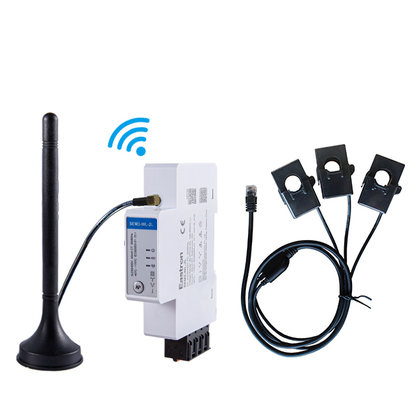
CT Type Three Phase Din Rail Wifi Energy Meter for PV Metering
May 30,2025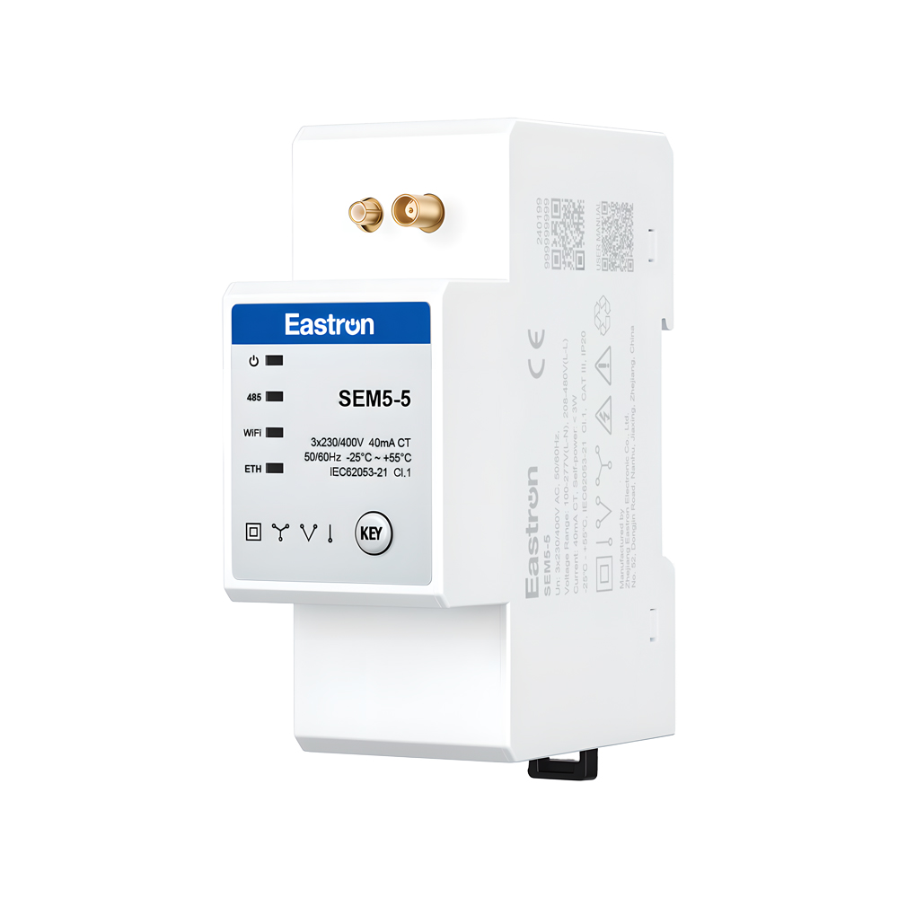
CT Operated Wireless Three Phase Energy Meter for PV Metering
May 30,2025
Wifi & LoRa Three Phase Din Rail Energy Meter for PV Metering
Sep 19,2025
MID 3 Modules Din Rail Three Phase Direct Multi-function Meter for EV Charging Metering
Aug 02,2022Content

Electricity distribution systems are becoming more complex. Commercial buildings, industrial plants, renewable-energy installations, data centers, transport facilities, and infrastructure projects all require dependable information about voltage, current, power, energy, frequency, and power factor. At the same time, many electrical installations are being upgraded without completely replacing their existing conductors or switchboards. These conditions create a demand for measuring equipment that is accurate, compact, easy to install, and suitable for digital communication.
The Smart X96-3RC is designed for this environment. It is a three-phase multifunction panel meter that works directly with Rogowski coils and provides a broad set of electrical measurements through a clear front display. The meter supports three-phase three-wire and three-phase four-wire systems, includes RS485 Modbus RTU communication, provides pulse output, and offers a Class 0.5S active-energy accuracy level under the stated standards.
Rather than serving only as a basic current or voltage indicator, the meter combines measurement, display, communication, and distribution-panel integration in one instrument. Its 96 mm panel format, plug-in connection approach, backlit LCD, bar graph indication, and configurable Rogowski coil input make it suitable for both new installations and modernization projects.
Electrical distribution equipment must do more than deliver power. Operators also need to understand how that power is being used, where losses may occur, whether equipment is operating within normal limits, and how demand changes over time. A meter that measures only one variable often requires additional devices, wiring, and panel space. A multifunction meter can consolidate these tasks.
The Smart X96-3RC measures the principal electrical characteristics of an AC distribution system. Depending on the installation and configuration, users can obtain information about voltage, current, frequency, active power, reactive power, apparent power, power factor, and active or reactive energy. Energy values can be monitored in imported and exported directions, helping users understand both consumption and generation.
This range of information is valuable in several situations. An industrial operator may use current and power readings to identify overloaded feeders. A facilities manager may compare active energy across building zones. A solar or energy-storage installation may need to distinguish imported energy from exported energy. A maintenance engineer may examine voltage, frequency, and power factor before investigating a motor or power-quality issue.
By bringing these measurements together, the meter reduces the need to install separate instruments for each parameter. This can make a panel easier to read and can simplify the architecture of a monitoring system. It also creates a consistent measurement point for a supervisory platform, building management system, energy-management system, or industrial control application.
One of the main features of the Smart X96-3RC is its direct Rogowski coil connection. A Rogowski coil is a flexible current sensor that can be placed around a conductor without requiring the conductor to pass through a rigid magnetic core. This design is particularly useful when the conductors are large, crowded, or difficult to disconnect.
Traditional current transformers can be highly effective, but their rigid form factor may make installation difficult on large busbars or existing cables. They may also require more space and careful mechanical alignment. A flexible Rogowski coil can often be fitted around a conductor with less disruption to the existing installation. This is valuable during retrofit work, where shutting down a distribution board for extensive modification may be undesirable.
The meter is configured to work with a wide range of Rogowski coils directly and does not require an external integrator, according to the supplied product information. This is an important distinction in a practical installation. An external integrator adds another device, another set of terminals, another potential failure point, and additional panel-space requirements. Direct connection can simplify the signal path between the sensor and the measuring instrument.
The specified rated current input is 85 mV/kA, with a maximum current range of 1 kA or 5 kA. The correct coil and meter configuration should always be selected according to the conductor size, expected current, system voltage, and installation requirements. Correct sensor positioning and phase identification remain essential for accurate power and energy calculations.
Rogowski coils also provide a useful solution for temporary surveys and phased upgrades. A facility may initially install the sensors on selected feeders, collect operating data, and then expand monitoring to other circuits. Because the coils are lightweight and flexible, this approach can be more convenient than replacing existing current transformers throughout a distribution system.
Direct connection offers several practical benefits compared with a measurement arrangement that depends on separate signal-conditioning equipment:
First, it can reduce the number of components in the measuring chain. Fewer components may simplify commissioning and make fault tracing more straightforward.
Second, it can reduce wiring complexity. The installer does not have to route separate connections between the coil, an external integrator, and the panel meter.
Third, it can conserve panel space. This is especially relevant in compact switchboards, machine panels, and retrofit enclosures where every available mounting position is important.
Fourth, it can improve project consistency. When the meter is designed for direct Rogowski coil input, the sensor interface and display instrument are selected as a coordinated solution rather than assembled from unrelated devices.
These benefits do not eliminate the need for proper engineering. The installer must verify the coil specification, phase sequence, polarity, current range, insulation requirements, and local electrical regulations. However, the integrated input design can make the overall system more efficient to deploy.
The Smart X96-3RC is intended for RMS measurement on three-phase AC systems. It supports 3P3W and 3P4W configurations, with the stated measured-voltage ranges of 50 V to 600 V for three-phase four-wire systems and 50 V to 480 V for three-phase three-wire systems.
In a three-phase four-wire installation, the meter can be used in systems containing three phase conductors and a neutral conductor. This arrangement is common in commercial buildings, manufacturing facilities, and low-voltage distribution boards. Three-phase three-wire systems are also widely used in industrial equipment and motor distribution networks.
The product information also identifies measurement capability for single-phase two-wire systems. The exact wiring method and menu configuration should be confirmed from the applicable installation documentation before commissioning. In all cases, the meter should be connected by qualified personnel using appropriate protective devices and isolation procedures.
The instrument measures several power quantities. Active power represents the portion of electrical power converted into useful work, heat, or other energy forms. Reactive power is associated with magnetic and electric fields in inductive and capacitive equipment. Apparent power represents the combined voltage-current loading that the distribution system must carry. Viewing these values together provides a more complete picture than monitoring active power alone.
Power factor is also displayed. A low power factor can increase current for a given active load and may contribute to additional losses or capacity constraints. Monitoring power factor can help operators evaluate motors, transformers, lighting systems, converters, and power-factor-correction equipment.
Frequency measurement provides an additional indication of system condition. The stated frequency accuracy is 0.2% of mid-frequency. This measurement may be useful when checking generator systems, isolated networks, or installations where frequency stability is important.
Measurement accuracy is central to the usefulness of any energy meter. The Smart X96-3RC provides an active-energy accuracy level of Class 0.5S according to IEC 62053-22 and IEC 61557-12, as specified in the product information. Reactive energy is identified as Class 2 under IEC 62053-23 and IEC 61557-12.
The supplied specifications also state accuracy figures for other measured quantities. Active, reactive, and apparent power are listed at 1.0% of the range maximum. Current and voltage are listed at 0.5% of the range maximum, while power factor is specified at 1% of unity, or 0.01. These values provide users with a basis for selecting the meter for distribution monitoring and energy-management applications.
| Measured parameter | Stated accuracy or class | Practical significance |
|---|---|---|
| Active energy | IEC 62053-22 Class 0.5S; IEC 61557-12 Class 0.5S | Suitable for high-quality energy monitoring and allocation applications within the installation design limits |
| Reactive energy | IEC 62053-23 Class 2; IEC 61557-12 Class 2 | Supports monitoring of reactive-energy behavior and power-factor performance |
| Active power | 1.0% of range maximum | Useful for observing feeder loading and operating demand |
| Reactive power | 1.0% of range maximum | Helps evaluate inductive or capacitive loading |
| Apparent power | 1.0% of range maximum | Supports assessment of overall equipment and feeder loading |
| Current | 0.5% of range maximum | Provides a dependable indication of circuit current |
| Voltage | 0.5% of range maximum | Supports voltage supervision and operating checks |
| Frequency | 0.2% of mid-frequency | Provides an indication of supply-frequency stability |
| Power factor | 1% of unity, 0.01 | Helps identify inefficient or highly reactive operating conditions |
Accuracy in the field depends not only on the meter itself. Sensor selection, coil installation, wiring, phase sequence, voltage-transformer configuration when applicable, environmental conditions, and regular verification all affect system performance. The meter’s stated accuracy should therefore be considered together with the accuracy of the complete measurement chain.
Remote monitoring is increasingly important, but local visibility remains essential. An operator standing at a distribution panel should be able to determine the condition of the system without connecting a laptop or opening a software interface. The Smart X96-3RC uses a backlit LCD display designed for full viewing angles, making it suitable for panel-mounted observation.
The display presents measured values directly at the point of installation. This can shorten inspection time during maintenance rounds and help technicians confirm operating conditions after commissioning. A backlight improves readability in equipment rooms, electrical cabinets, and areas with inconsistent lighting.
A bar graph for power indication provides a quick visual representation of loading. Numerical values are important for detailed analysis, but a graphical indication can help an operator recognize whether a feeder is lightly loaded, operating near its normal level, or approaching a high-load condition.
The front-panel arrangement is intended to combine information density with straightforward operation. Depending on the configured display pages, users can review different electrical parameters and energy values without requiring separate instruments. The local interface is particularly useful during testing, troubleshooting, and routine inspection.
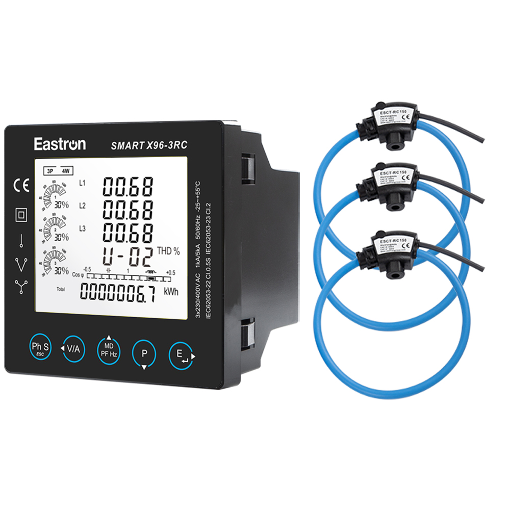
Rogowski Coils Connected Three Phase Multi-function Panel meters for Electricity Distribution
The meter includes an RS485 communication port using Modbus RTU. This communication method is widely used in industrial automation, building management, energy monitoring, and equipment-control systems. It allows the meter’s data to be collected by a supervisory device, data logger, gateway, programmable controller, or energy-management software platform.
RS485 is well suited to distribution panels because it supports communication over practical cable distances and can connect multiple addressed devices on a bus. The Smart X96-3RC provides configurable communication parameters that include baud rates of 2400, 4800, 9600, 19200, and 38400 bits per second. The address range is listed as 1 to 247. Parity options include none, even, and odd, while one or two stop bits are supported.
These options make the meter easier to integrate into different communication architectures. A small installation may use a single meter connected to a local controller. A larger facility may connect many meters through an RS485 network and use a gateway to transfer data to a centralized platform.
Modbus RTU integration also supports structured energy-management practices. Data can be used to create dashboards, compare departments, monitor peak demand, evaluate production-line consumption, and identify unusual operating patterns. When combined with time-based data collection, the meter can contribute to energy baselining and efficiency projects.
The product information also specifies pulse output. Pulse outputs are useful when an external device needs a simple energy-counting signal. They can be connected to compatible data-acquisition equipment, counters, controllers, or legacy monitoring systems. In a mixed-technology facility, the pulse output can provide a practical link between a modern multifunction meter and an existing counting system.
Communication and pulse functions should be wired according to the product manual. RS485 networks should use appropriate cable practices, addressing, termination, and grounding arrangements. The communication network should also be separated from high-energy conductors where required by the installation design.
Remote access changes the role of a panel meter from a local indicator into a data source for operational decision-making. Instead of visiting each switchboard to record readings, a facility team can collect information from multiple locations. This can improve visibility while reducing routine inspection time.
Remote monitoring can also support alarms. A supervisory system may be configured to notify operators when voltage, current, power, power factor, or energy behavior moves outside an expected range. Although the meter itself is primarily a measurement device, its communication capabilities allow higher-level software to apply site-specific rules and responses.
For multi-tenant properties or production facilities, the meter can support energy allocation. Individual feeders, floors, workshops, or process areas can be measured separately. The resulting data can help organizations understand where energy is consumed and whether efficiency improvements are delivering measurable results.
The meter has a 96 mm by 96 mm front format and a depth of 70 mm. This is a familiar size for panel-mounted electrical instruments and can simplify replacement planning where an existing panel has a compatible cutout. The product information identifies vertical panel cut-out installation and a push-in installation approach with plug-in connection.
Push-in installation can make mounting more convenient during panel assembly. Plug-in connections can also support easier service or replacement, provided that the wiring arrangement and safety procedures permit such work. The terminals are specified as shrouded screw-clamp terminals, which help secure conductors while providing additional protection around the connection area.
The meter case uses self-extinguishing UL 94 V-0 material. This material designation indicates a high level of flame-retardant performance under the relevant test method. It is an important consideration for equipment installed within electrical panels, although the complete enclosure and installation must still comply with the applicable electrical and fire-safety requirements.
The front display has an IP51 degree of protection according to IEC 60529. This provides protection appropriate to many indoor panel applications when the meter is correctly installed. IP51 is not a substitute for a sealed outdoor enclosure, and the complete panel environment should be evaluated for dust, moisture, condensation, chemicals, vibration, and temperature.
| Mechanical feature | Specification |
|---|---|
| Meter dimensions | 96 mm wide x 96 mm high x 70 mm deep |
| Installation style | Panel mounting with push-in installation |
| Connection style | Plug-in connection and shrouded screw-clamp terminals |
| Front protection | IP51 display protection according to IEC 60529 |
| Case material | Self-extinguishing UL 94 V-0 material |
| Weight | Approximately 420 g |
The auxiliary power supply is specified as 230 V line-to-neutral AC or 120 V to 380 V DC. The supply arrangement should be confirmed against the actual project design before ordering and installation. Suitable overcurrent protection and isolation should be provided in accordance with local regulations and the panel design.
The stated operating-temperature range is -25°C to 55°C. The storage-temperature range is -40°C to 70°C. The humidity rating is below 95% relative humidity at 50°C, non-condensing. The product information also identifies pollution degree 2 and an altitude rating of up to 3000 m.
These specifications allow the meter to serve in many indoor industrial and commercial environments. Nevertheless, an installation engineer should review the actual site conditions. A cabinet located near furnaces, outdoor switchgear, refrigeration equipment, chemical processes, or areas with condensation may need additional thermal management or environmental protection.
Pollution degree and humidity are especially important in distribution systems. Conductive dust, corrosive vapors, condensation, and water ingress can affect terminals and insulation even when the meter is within its nominal temperature range. Proper cabinet selection, ventilation, sealing, and maintenance remain necessary for reliable service.
Manufacturing plants often contain many feeders serving motors, heaters, compressors, conveyors, and process equipment. The Smart X96-3RC can be installed at selected distribution points to measure current, power, energy, and power factor. This allows engineers to compare the behavior of different production areas and identify circuits that require closer attention.
In offices, retail facilities, hotels, hospitals, and educational buildings, energy use is distributed across lighting, HVAC, elevators, pumps, kitchens, and tenant areas. A multifunction meter can provide more detailed information than a single utility meter. RS485 communication makes it possible to bring readings into a building-management or energy-management system.
Data centers require careful monitoring of electrical loading because equipment operates continuously and power availability is closely linked to service continuity. The meter can be used on selected distribution paths to observe voltage, current, apparent power, active energy, and power factor. Flexible Rogowski coils can be advantageous when conductors are large or densely arranged.
Solar photovoltaic systems, battery storage systems, and hybrid power installations may both import and export energy depending on operating conditions. The ability to monitor imported and exported active and reactive energy can help operators understand the direction and scale of energy flow. The meter should be applied within the voltage, current, wiring, and protection limits of the system.
Energy audits often require measurement without extensive modification to existing switchboards. Flexible current sensors can be installed around conductors during a planned survey, subject to safe working procedures. The meter’s local display and communication port can support both immediate observation and later data collection.
Large machines may have several loads that are difficult to evaluate using only the main control system. A dedicated panel meter can provide an independent measurement point. This can help maintenance teams distinguish between electrical supply problems and mechanical or process-related issues.
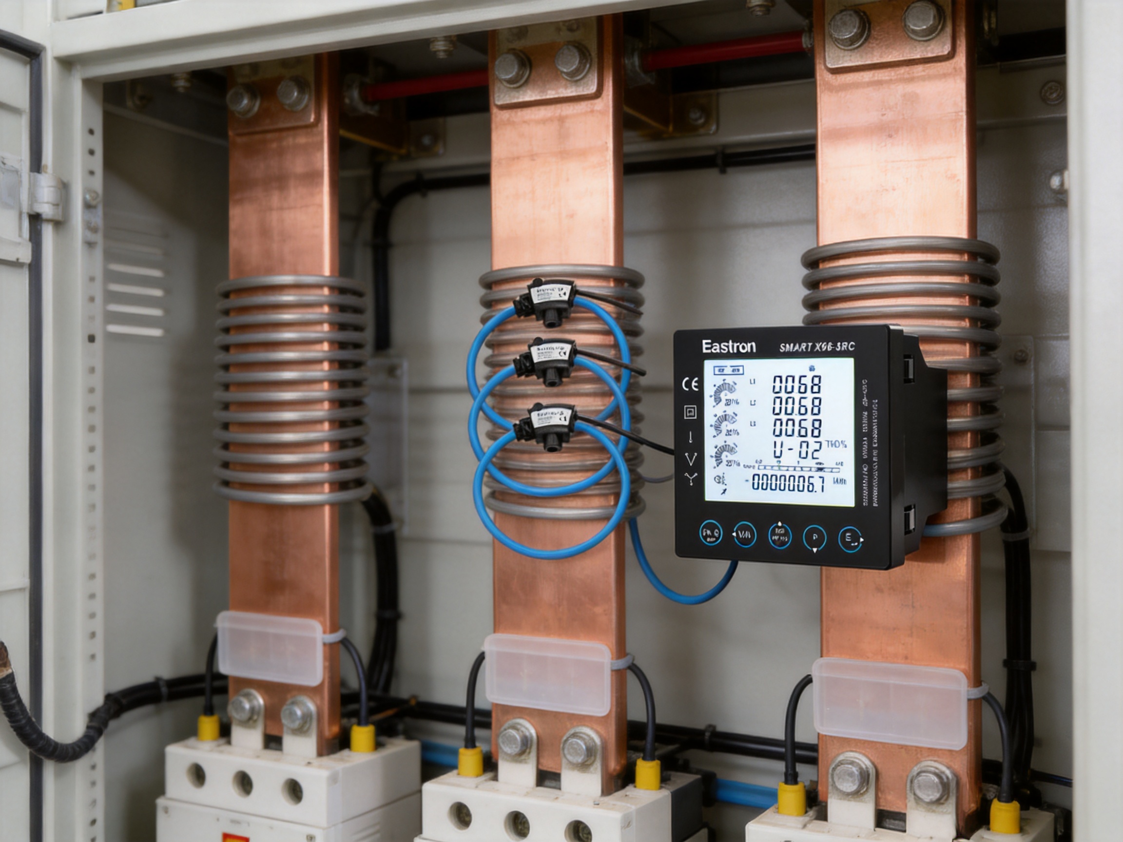
The product’s principal advantage is integration. A conventional installation might use separate current indicators, voltage meters, power meters, energy meters, and communication modules. The Smart X96-3RC combines many of these functions in one panel instrument, reducing duplication and creating a unified user interface.
Another advantage is the combination of flexible sensing and digital communication. A rigid current transformer may be difficult to install around an existing busbar, while a simple local indicator may not provide the data needed by a modern energy platform. The Rogowski coil interface addresses the mechanical challenge, and RS485 Modbus RTU addresses the data-integration challenge.
The 96 mm panel format is also advantageous for standard control-panel layouts. A compact instrument can be installed close to breakers, contactors, protection relays, and other control devices without requiring a large additional enclosure. Its 420 g weight and plug-in connection design can make handling easier during panel assembly.
The backlit full-viewing-angle LCD provides a benefit over meters that are difficult to read from the side or in poor lighting. The bar graph provides an additional visual cue, which is useful when technicians need to evaluate loading quickly.
The Class 0.5S active-energy specification is another important point of differentiation for applications where energy measurement quality matters. It supports more precise energy monitoring than basic indication-only instruments, subject to correct installation and the performance of the complete sensor system.
Compared with systems that use an external Rogowski coil integrator, direct input can reduce equipment count and simplify commissioning. Compared with single-function meters, multifunction measurement can reduce panel space, wiring, and the number of communication nodes. Compared with non-networked instruments, Modbus RTU and pulse output provide more options for data collection.
These advantages should be evaluated against the requirements of each project. The meter is not intended to replace every protection relay, power-quality analyzer, or certified revenue meter. Instead, it is a versatile distribution-monitoring instrument that combines a strong set of functions in a practical panel format.
Eastron Electronic Co., Ltd. is described in the supplied information as a high-tech manufacturer and supplier of electricity products and energy-measurement solutions. Its product range includes electricity meters, power analyzers, current sensors, communication modules, and management systems. This broader portfolio is relevant because it indicates experience across multiple parts of the measurement chain rather than in only one type of instrument.
The company develops and produces products through teams in China and the United Kingdom. Its development approach combines internal engineering resources with cooperation involving universities and technical institutions. Such cooperation can help bring new methods in electronics, embedded software, measurement algorithms, and communication design into commercial products.
The company’s own professional laboratory is identified as capable of performing electromagnetic compatibility, low-voltage directive, accuracy, and environmental testing according to IEC, EN, GB, and UL standards. In-house testing can offer important manufacturing advantages. It allows engineers to evaluate prototypes earlier, investigate failures more efficiently, and repeat tests during design changes without relying exclusively on external facilities.
For a multifunction meter, testing must cover more than basic display operation. Accuracy should be checked across relevant current and voltage conditions. Communication should be tested under different baud-rate and addressing configurations. Environmental tests should consider temperature and humidity. EMC testing is important because meters are installed near switching equipment, contactors, variable-speed drives, and other sources of electrical disturbance.
The company also reports patented technologies in software, embedded software, and hardware. Patents alone do not determine product quality, but they indicate ongoing investment in the technical architecture behind the products. Embedded measurement devices require stable firmware, reliable parameter storage, robust communication handling, and carefully developed signal-processing methods.
Recognition as a high-tech enterprise and high-tech research and development center of electricity application further reflects the company’s emphasis on technical development. The stated ISO 9001 quality-management system provides a framework for documented processes, corrective actions, supplier control, production consistency, and continual improvement.
A strong manufacturing process begins before assembly. Product requirements must be translated into electrical designs, mechanical designs, firmware functions, test procedures, and production documents. Components must be selected for performance, availability, environmental suitability, and long-term reliability.
During production, controlled assembly procedures help ensure that display modules, terminals, circuit boards, communication interfaces, and sensor inputs are fitted consistently. Calibration and functional testing are particularly important for measurement products. Each finished meter should be checked against defined acceptance criteria before shipment.
Traceability is also important. A well-managed manufacturing process can connect finished products to production batches, component information, inspection records, and test results. This supports corrective action if a quality issue is identified and helps maintain confidence across international markets.
Because the company supplies products to customers in Europe, Asia-Pacific, America, the Middle East, and Africa, it must address a range of electrical practices, environmental conditions, documentation expectations, and communication requirements. International experience can help the manufacturer understand how panel meters are applied in different system architectures.
Before selecting the meter, the project engineer should identify the electrical system configuration. The system may be three-phase three-wire or three-phase four-wire, and the voltage must fall within the applicable range. The current range should be selected according to the Rogowski coil and the expected maximum load.
The installer should verify that the voltage connections are protected and correctly identified. Current sensors must be installed around the intended conductors, with correct phase association. Reversed phase relationships or incorrect coil orientation can affect power, energy, and power-factor readings even when voltage and current values appear plausible.
The panel cutout and available depth should be checked before installation. The specified meter dimensions are 96 mm by 96 mm by 70 mm, but additional clearance may be required for wiring, ventilation, terminal access, and service work. The panel should provide suitable protection against the surrounding environment.
Communication wiring should be planned before commissioning. Each meter on an RS485 network needs a suitable address. Baud rate, parity, and stop-bit settings must match the master device. Cable routing, shielding, termination, and grounding should follow the network design and applicable technical guidance.
After installation, the commissioning process should include a visual inspection, verification of supply voltage, confirmation of phase sequence, comparison with a trusted reference where appropriate, and a communications test. The operator should also confirm that the displayed units, energy direction, and configured coil range correspond to the actual system.
Only qualified personnel should install or service equipment connected to energized electrical systems. Isolation, lockout, verification of absence of voltage, appropriate personal protective equipment, and local safety procedures are essential.
Energy management begins with measurement. Without reliable data, improvement programs are often based on assumptions or incomplete utility bills. A multifunction meter can provide circuit-level information that makes energy use more visible and actionable.
For example, a facility may discover that a production feeder continues to consume substantial power during scheduled downtime. A power-factor trend may reveal that a bank of motors or transformers is operating inefficiently. A comparison between similar buildings may show that one HVAC system consumes more energy than expected. These findings can support targeted maintenance and investment decisions.
Energy data can also support verification. After installing efficient motors, improving controls, changing operating schedules, or adding power-factor correction, the organization can compare measured performance before and after the intervention. This helps determine whether the project delivered its intended result.
At a broader level, networked meters can contribute to carbon-accounting and sustainability programs. Electrical energy data can be mapped to departments, processes, tenants, or production units. When combined with appropriate emission factors and operating records, the data can support more transparent reporting.
The Smart X96-3RC is therefore not only a display instrument. When connected through Modbus RTU or pulse output, it can become part of an information system that supports operational control, maintenance planning, energy allocation, and long-term efficiency improvement.
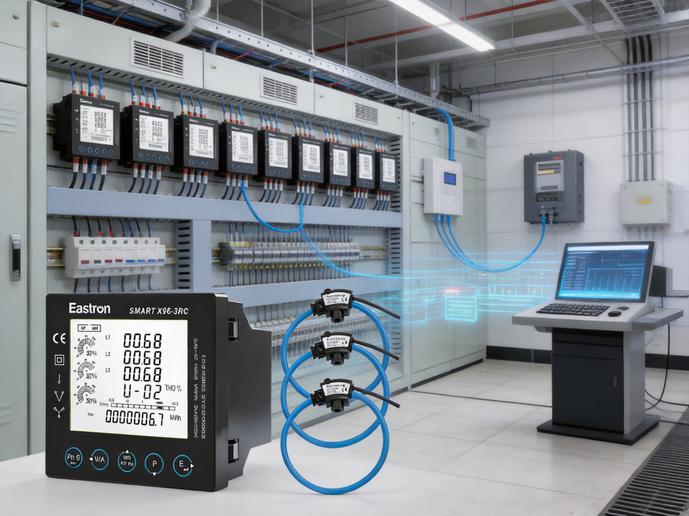
It is a three-phase multifunction panel meter for electricity distribution. It measures and displays electrical parameters such as voltage, current, frequency, power, energy, and power factor.
The meter uses Rogowski coils. It is designed for direct Rogowski coil connection and is specified with an 85 mV/kA rated-current input. The appropriate sensor range should be selected according to the installation.
According to the supplied product information, the meter can be configured to work with a wide range of Rogowski coils directly and does not require an external integrator.
The product content identifies support for three-phase three-wire and three-phase four-wire systems. The information also references single-phase two-wire measurement capability. The wiring configuration should be confirmed against the official installation documentation.
The stated measured-voltage range is 50 V to 600 V for a three-phase four-wire system and 50 V to 480 V for a three-phase three-wire system.
The meter provides RS485 communication using Modbus RTU. It supports configurable baud rates from 2400 to 38400 bits per second, addresses from 1 to 247, selectable parity, and one or two stop bits.
Yes. Pulse output is listed among the product’s features. It can be used with compatible counting or data-acquisition equipment.
Active energy is specified as Class 0.5S according to IEC 62053-22 and IEC 61557-12.
The product information states that it measures active and reactive energy in imported or exported directions. The configured wiring and system application should be checked during commissioning.
The meter measures 96 mm wide, 96 mm high, and 70 mm deep. Its approximate weight is 420 g.
The front display is rated IP51, making it suitable for many protected indoor panel applications. Outdoor use requires an appropriate enclosure and an evaluation of temperature, humidity, condensation, dust, and other site conditions.
The operating temperature is -25°C to 55°C. The storage temperature is -40°C to 70°C. The humidity rating is below 95% relative humidity at 50°C, non-condensing, with a stated altitude limit of 3000 m.
It provides a broader group of measurements, local display, Rogowski coil compatibility, RS485 Modbus RTU communication, pulse output, power indication, and active-energy Class 0.5S performance. These features can reduce the need for several separate instruments.
Direct Rogowski coil input can reduce component count, wiring, and panel-space requirements. It may also simplify commissioning because the coil interface is integrated into the meter. The complete installation must still be designed and tested correctly.
Installation should be performed by qualified electrical personnel familiar with panel construction, current sensors, RS485 networks, electrical safety, and the applicable local regulations.
The Smart X96-3RC combines flexible current sensing, multifunction electrical measurement, local display, and digital communication in a compact panel meter. Its direct Rogowski coil input is well suited to large conductors, crowded panels, retrofit projects, and installations where rigid current transformers are inconvenient. Its support for three-phase three-wire and three-phase four-wire systems provides application flexibility across industrial and commercial distribution networks.
The meter’s Class 0.5S active-energy performance, broad measurement capability, backlit LCD, bar graph indication, RS485 Modbus RTU interface, and pulse output make it more than a basic panel indicator. These functions support local inspection as well as centralized energy monitoring. The 96 mm format, plug-in connection approach, shrouded terminals, and UL 94 V-0 case material further support practical panel integration.
Its competitive value comes from combining functions that are often distributed across several separate components. Direct Rogowski coil compatibility can simplify the measurement architecture, while communication features help connect the instrument to modern energy-management systems. The result is a practical solution for electricity distribution monitoring, retrofit measurement, equipment supervision, and energy-efficiency programs.
The manufacturer’s broader expertise in electricity products, current sensors, communication modules, and management systems strengthens the product offering. Its reported laboratory capabilities, standards-oriented testing, research and development activities, patented technologies, ISO 9001 quality-management system, and international customer experience provide a foundation for reliable production and continued product development.
For engineers selecting a panel meter, the final decision should consider system voltage, sensor range, wiring configuration, accuracy requirements, communications architecture, environmental conditions, and local regulations. When these factors are correctly matched, the Rogowski coil connected multifunction meter can provide a dependable measurement point for clearer, safer, and more efficient electricity distribution management.
IEC 62053-22, Electricity metering equipment: particular requirements for static meters for active energy, accuracy classes 0.1S and 0.2S.
IEC 62053-23, Electricity metering equipment: particular requirements for static meters for reactive energy.
IEC 61557-12, Electrical safety in low-voltage distribution systems: power metering and monitoring devices.
IEC 60529, Degrees of protection provided by enclosures.
UL 94, Tests for flammability of plastic materials for parts in devices and appliances.
Modbus Application Protocol Specification, Modbus communication principles and data exchange practices.
Rogowski Coil Measurement Principles, technical guidance on flexible current sensors, signal integration, installation, and phase identification.
Quality Management Systems, ISO 9001 principles for product design, manufacturing control, testing, and continual improvement.
Your email address will not be published. Required fields are marked *

We develop and produce high performance electricity meters, power analyzers, current sensors, communication modules and management systems.
Address:NO. 52, Dongjin Road, Nanhu, Jiaxing, Zhejiang, China
Copyright @ Eastron Electronic Co., Ltd. All rights reserved
