

 English
 Español
 Deutsch
 中文简体


Product Consultation
Your email address will not be published. Required fields are marked *
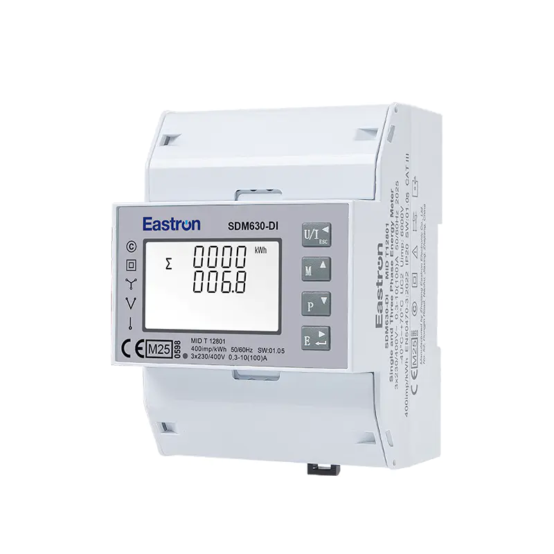
MID & UL Approved Three Phase Din Rail Type Multi-function Energy Meter for EV Charging Metering
Nov 24,2022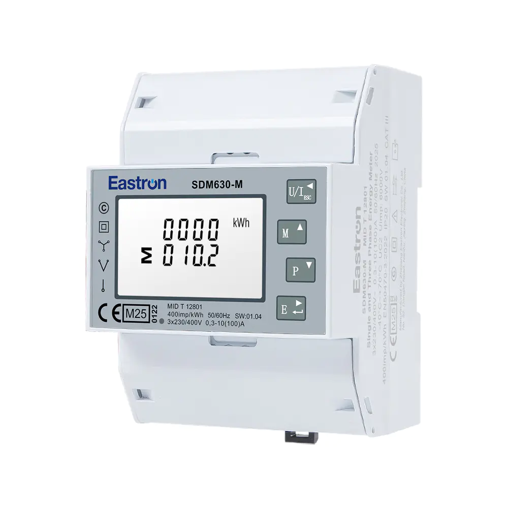
MID UL Certified Din Rail Three Phase Multi-function Energy Meter for EV Charging Metering
Aug 02,2022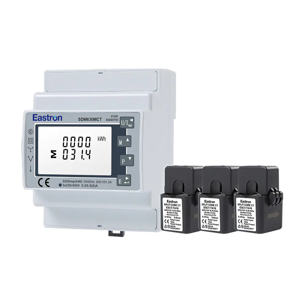
MID/UL CT Type Din Rail Three Phase Multi-function Energy Meter for EV Charging Metering
Nov 24,2022
MID Din Rail Three Phase Multi-function Solar PV /Zero Export Meter for PV Metering
Aug 02,2022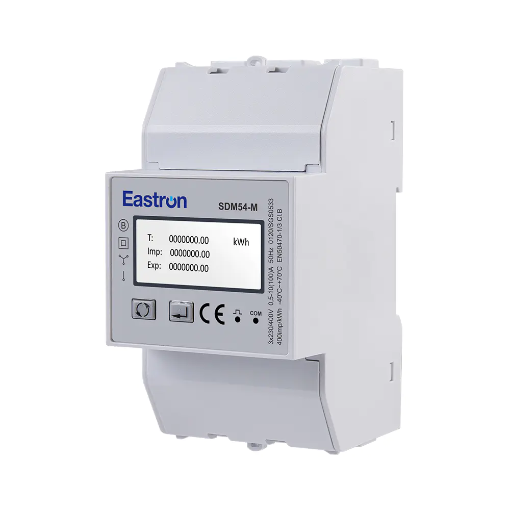
MID 3 Modules Din Rail Three Phase Multi-function Solar PV /Zero Export Meter for PV Metering
Aug 02,2022
RS485 CT Connection Three Phase Din Rail Energy Meter for PV Metering
May 30,2025Content
Modern electrical installations require more than a simple kilowatt-hour counter. Commercial buildings, industrial facilities, renewable-energy systems, electrical distribution panels, and energy-management platforms increasingly need accurate measurements of voltage, current, active power, reactive power, apparent power, power factor, frequency, demand, and imported or exported energy. They also need reliable communication so that measured information can be transferred to a building-management system, data concentrator, or remote monitoring platform.
The SDM630-Mbus V2 addresses these requirements in a compact DIN-rail format. It is a multifunctional three-phase energy meter designed for direct connection up to 65 A. The meter supports 3P3W, 3P4W, and 1P2W electrical systems, includes pulse outputs, and provides M-Bus communication according to EN 13757. Its four-module, 72 mm housing allows it to fit efficiently into distribution boards and metering cabinets where panel space is limited.
Beyond energy accumulation, the meter provides a broad range of electrical measurements. Users can monitor active energy in kWh, reactive energy in kVarh, active power in W, reactive power in var, apparent power in VA, power factor, frequency, voltage, current, demand, and related system parameters. Bidirectional measurement allows the device to record energy imported from the grid and energy exported to the grid, making it suitable for installations with photovoltaic generation, battery storage, regenerative equipment, or other distributed energy resources.
The product is also designed around practical installation and integration requirements. Its direct 65 A current capability can eliminate the need for external current transformers in many applications. Its pulse outputs can connect to pulse counters and basic energy-management systems, while the M-Bus interface can communicate with centralized metering infrastructure over long cable runs. These features help reduce system complexity while preserving the flexibility needed for modern energy monitoring.
This article explains the meter’s operating capabilities, technical advantages, application value, communications architecture, installation considerations, and the manufacturing strengths behind its development. It also compares the design approach with common alternatives and provides a detailed question-and-answer section for engineers, installers, system integrators, facility managers, and purchasing teams.
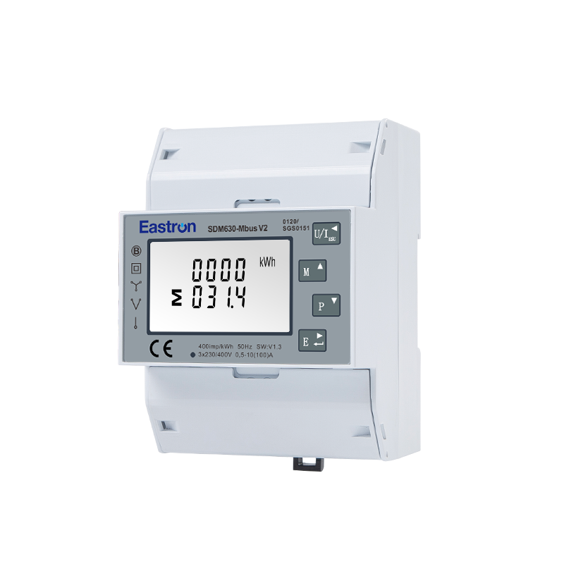
Mbus Multi-functional Three Phase Din Rail ETL Energy Meter
The SDM630-Mbus V2 is a three-phase multifunction energy meter for DIN-rail installation. It is intended for systems in which electrical energy must be measured, displayed, recorded, and transmitted to an external monitoring or control platform. The product combines direct current measurement, multi-parameter analysis, energy accumulation, pulse signaling, and M-Bus communication in one compact instrument.
The meter can be used with three-phase, three-wire systems, commonly identified as 3P3W, and three-phase, four-wire systems, identified as 3P4W. It can also support single-phase, two-wire applications. This range of wiring configurations gives electrical contractors and system designers greater freedom when selecting one meter family for different panel types and installation projects.
With a maximum direct current of 65 A, the meter is suitable for many small and medium-sized final circuits, sub-distribution boards, commercial loads, equipment feeders, and small-generation systems. Direct connection means that the phase conductors can be routed through the meter without installing separate current transformers for the supported current range. This can reduce the number of components, shorten installation time, simplify wiring, and avoid the ratio-setting and polarity concerns associated with external CTs.
The meter has a rated current of 10 A and a maximum current of 65 A. The specified minimum current is 0.5 A, while the starting current is 40 mA. Its rated voltage is 230 V line-to-neutral or 120 V line-to-neutral, with an operational voltage range of 80% to 120% of the rated value. Engineers should always verify the complete installation voltage, phase arrangement, protective-device ratings, and local electrical requirements before commissioning the unit.
A four-module housing with a width of 72 mm provides a practical compromise between functionality and panel density. Compared with larger panel meters or systems requiring separate CT blocks, signal converters, and communication modules, this format can help preserve valuable space inside electrical cabinets. The front display and control buttons provide local access to measured values and configuration parameters, while password protection helps prevent unauthorized changes.
The product is designed as a multifunction instrument rather than a single-purpose energy register. Its measurement functions include voltage, current, frequency, active power, reactive power, apparent power, power factor, active energy, reactive energy, and demand-related information. Such a combination allows users to understand not only how much energy a circuit consumes, but also how the circuit behaves electrically.
Active energy indicates the energy used or generated by a load and is normally expressed in kWh. Reactive energy, expressed in kVarh, helps users evaluate the reactive component associated with motors, transformers, lighting equipment, power electronics, and other inductive or capacitive loads. Active power indicates the useful real-time power flow, while reactive and apparent power provide additional information about system loading and power quality conditions.
Power factor is particularly useful in commercial and industrial facilities. A low power factor can cause higher current for a given active power, increase losses, reduce available capacity, and potentially lead to utility penalties depending on the local tariff structure. By displaying power factor alongside current and power, the meter helps maintenance teams identify circuits that may benefit from power-factor correction or load optimization.
Frequency measurement supports basic verification of supply stability. Voltage and current readings help operators identify abnormal loading, phase imbalance, undervoltage, or overvoltage conditions. Although the meter is not a replacement for a specialized power-quality analyzer in advanced harmonic or transient investigations, its RMS measurement approach provides useful operational information for routine energy supervision.
Measurement quality is central to the value of any energy meter. The SDM630-Mbus V2 specifies voltage accuracy of ±0.5%, current accuracy of ±0.5%, frequency accuracy of ±0.2%, and power-factor accuracy of ±1%. Active power, reactive power, and apparent power are each specified at ±1% under the applicable operating conditions.
For energy accumulation, active energy is rated Class 1.0 according to IEC 62053-21, while reactive energy is rated Class 2 according to IEC 62053-23. These classifications provide a recognized basis for evaluating metering performance. The actual accuracy achieved in an installation depends on factors such as supply stability, conductor arrangement, load level, waveform characteristics, ambient conditions, correct wiring, and compliance with the installation instructions.
The meter uses RMS measurement, including harmonics, on three-phase AC systems. This is important because many contemporary loads do not draw perfectly sinusoidal current. Variable-frequency drives, switch-mode power supplies, LED drivers, computers, chargers, and inverter-based equipment can introduce waveform distortion. An RMS-based approach that includes harmonic content gives a more representative view of the electrical quantities present on the circuit than a basic average-responding instrument.
Accuracy should be considered across the complete measurement chain. A direct-connected meter avoids the transformation error of an external CT, but the installer must still ensure that phase conductors are connected to the correct terminals and that the current direction is consistent with the intended import and export convention. Loose terminals, excessive conductor heating, incorrect neutral wiring, and unsuitable protection can all affect the reliability of the final measurement system.
The instrument also supports bidirectional measurement. This means that it can distinguish energy imported from the supply and energy exported toward the grid or another network. This function is especially valuable in solar installations, microgrids, battery systems, electric-vehicle charging sites, and facilities where onsite generation may exceed local consumption during certain operating periods.
Demand information helps users understand the highest or average power requirement over a defined interval rather than looking only at instantaneous power. The meter can measure maximum demand over preset periods of up to 60 minutes. Demand data can assist with tariff management, transformer utilization analysis, generator sizing, and load scheduling.
For example, a facility may have a moderate monthly energy consumption but experience short periods of high demand. These peaks can influence utility charges or require the operator to maintain a larger electrical service than the average load alone would suggest. By observing demand trends, the facility can stagger motor starts, reschedule high-power processes, adjust charging patterns, or improve energy-management strategies.
The SDM630-Mbus V2 provides two pulse outputs and an M-Bus interface based on EN 13757. The pulse outputs can be used for imported and exported energy, allowing a pulse counter, programmable logic controller, data logger, or building-management gateway to collect energy increments. Pulse signaling is simple and widely understood, making it appropriate for installations where only cumulative energy data is required.
M-Bus provides a more comprehensive communication path. Instead of transmitting only pulses, the communication interface can provide a broader group of measured and accumulated values to a compatible master device. This can reduce the need for separate instruments and enable centralized reading of multiple meters across a building or site.
M-Bus is especially common in building services, utility submetering, heating and cooling measurement, and multi-tenant facilities. A central M-Bus master can collect information from multiple field meters and pass it to an energy-management software platform. In this arrangement, the meter functions as an intelligent field device, while the master handles network polling, data storage, visualization, and higher-level analysis.
The specified M-Bus communication address range is 1 to 250. Transmission distance can reach up to 1,000 m under suitable cable, topology, master, and installation conditions. Supported baud rates range from 300 bps to 9,600 bps, with selectable parity options including none, odd, and even, and selectable stop bits of one or two. System designers should confirm that all meters, masters, cable types, termination practices, and communication settings are compatible.
It is important to distinguish M-Bus from Modbus. M-Bus is designed for meter communication and is commonly used in multi-meter reading systems. Modbus, frequently implemented over RS485, is a general industrial communication protocol. The SDM630 product family includes different variants, such as RS485 Modbus versions, M-Bus versions, pulse-only versions, tariff versions, digital-input versions, and Ethernet Modbus TCP versions. The SDM630-Mbus V2 specifically emphasizes M-Bus connectivity, so the chosen product code should be checked carefully before ordering.
Two pulse outputs remain useful even when M-Bus is installed. A facility may use M-Bus for detailed data collection while connecting pulse outputs to an independent verification system, local controller, or billing-related counter. This provides design flexibility and can support cross-checking between a primary communication network and a secondary accumulation method.
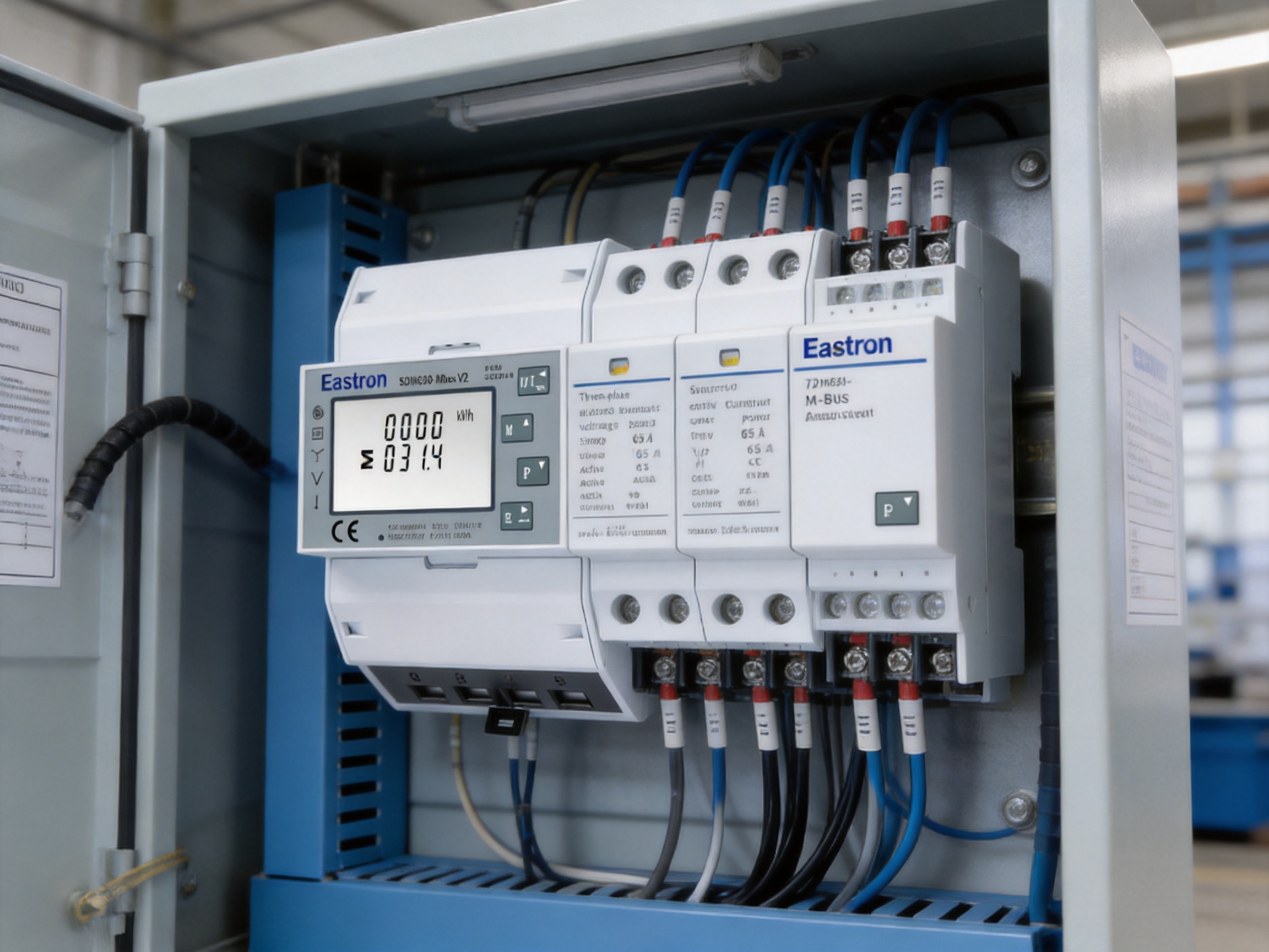
One of the most significant advantages of the meter is its ability to measure up to 65 A directly. Many conventional metering arrangements use external current transformers whenever current exceeds the instrument’s internal input capability. CTs are valuable for high-current applications, but they also introduce additional hardware, wiring, panel space requirements, procurement decisions, and commissioning steps.
A CT-based system requires correct selection of the transformation ratio, adequate insulation, suitable burden, correct polarity, secure secondary wiring, and appropriate treatment of the CT secondary circuit. Incorrect ratio settings can cause systematic measurement errors. Reversed CT polarity can make power or energy appear negative. Open-circuit CT secondaries can create hazardous voltage conditions in some installations. Direct connection avoids many of these CT-specific concerns for circuits within the meter’s current range.
Eliminating external CTs can also shorten the bill of materials. A project may require fewer terminal blocks, fewer enclosure accessories, fewer labels, and less space for current-sensing components. For contractors working on repetitive installations, these savings can improve assembly consistency and reduce the number of opportunities for wiring mistakes.
Direct connection does not mean that current protection can be omitted. The meter must be installed in accordance with applicable electrical codes, and the circuit must include suitable protective devices, isolation provisions, conductor sizing, and enclosure arrangements. The 65 A maximum is a product operating limit, not a recommendation to exceed the requirements of the supply system or local regulations.
DIN-rail mounting is widely used in low-voltage distribution boards, control panels, metering cabinets, and building-services enclosures. A standardized rail-mounted housing helps simplify mechanical design and allows installers to position the meter beside circuit breakers, contactors, surge-protection devices, communication gateways, and terminal blocks.
The 72 mm width, equivalent to four standard modules, provides enough front-panel area for a readable display and controls while remaining compact compared with many standalone multifunction instruments. This is beneficial in retrofit projects, where available cabinet space may already be constrained by existing breakers and wiring.
The housing design also supports a clean separation between the metering function and the broader control system. A facility can place the meter in a local distribution board, connect its M-Bus terminals to a communication trunk, and allow a remote software platform to manage historical data. This distributed architecture avoids routing every power conductor to a central control cabinet.
For reliable operation, installers should provide adequate clearance, avoid excessive heat sources, use appropriately rated conductors, and follow the specified wiring diagram. Terminals should be tightened to the recommended torque, and conductors should be stripped and inserted correctly. In environments with vibration, high humidity, dust, or extreme temperature, enclosure selection and environmental protection are especially important.
Support for 3P3W, 3P4W, and 1P2W systems increases the product’s usefulness across different electrical architectures. A 3P4W configuration includes three phase conductors and a neutral, while a 3P3W arrangement does not use a neutral conductor. Single-phase, two-wire measurement is suitable for many individual circuits and smaller installations.
The meter should be configured for the intended wiring arrangement before measurement data is interpreted. A mismatch between the physical wiring and the selected system type can produce incorrect voltage, power, or energy values. Commissioning should include a phase-by-phase verification, comparison against a trusted reference instrument where appropriate, and confirmation that import and export directions are reported correctly.
Where a project contains several wiring types, using a common meter family can simplify training, spare-parts management, documentation, and maintenance. However, each installation must still be evaluated for its voltage level, current range, system earthing arrangement, protective requirements, and communication topology.
A basic energy meter may provide only cumulative kWh. Such a meter can be adequate for simple submetering, but it gives limited insight into why energy consumption changes or whether an electrical system is operating efficiently. The multifunction capability of the SDM630-Mbus V2 provides a wider diagnostic picture without requiring separate voltage, current, power, and power-factor meters.
When a facility wants to investigate a high bill, a low power factor, an overloaded phase, or a changing production profile, additional electrical parameters are extremely useful. A multifunction meter can support this investigation directly at the distribution point. The result is a more informative measurement system with fewer individual devices to purchase, install, maintain, and calibrate.
External CTs remain necessary for many high-current feeders, but they can be unnecessary for circuits within the 65 A direct-measurement range. A direct-connected meter usually requires less panel space and can offer a simpler installation. It also avoids the need to manage CT ratios and secondary circuits.
The direct-input design is therefore particularly competitive in small commercial buildings, apartment submetering, retail units, workshops, office floors, equipment panels, and distributed renewable-energy systems. In larger industrial systems, CT-connected versions may still be more appropriate, and the selection should be based on current, voltage, safety, and measurement requirements rather than on one format alone.
Pulse-only submeters can be economical when the only requirement is cumulative energy counting. However, they depend on an external pulse receiver and generally do not provide the same breadth of real-time electrical information. The SDM630-Mbus V2 combines pulse outputs with a digital communication interface, allowing both simple pulse collection and more detailed M-Bus integration.
This combination gives system designers a migration path. A small installation can begin with pulse collection and later add an M-Bus master or gateway without replacing the meter. The same device can therefore support different levels of monitoring as project requirements develop.
Large panel-mounted power analyzers may provide advanced waveform analysis, event recording, harmonic studies, and other specialized functions. They are appropriate for high-level power-quality investigations and critical infrastructure. However, they may be excessive for routine submetering and can require more cabinet space, external sensors, and a more complex installation.
The SDM630-Mbus V2 occupies a practical position between a basic kWh counter and a high-end power-quality analyzer. It supplies essential multifunction measurements, bidirectional energy recording, demand information, pulse outputs, and M-Bus communication in a compact DIN-rail package. For many energy-management applications, this balance offers a lower-complexity solution without sacrificing the measurements most commonly needed by operators.
Office buildings, shopping facilities, hotels, restaurants, and mixed-use properties often require submetering for tenants, floors, departments, HVAC systems, lighting circuits, and service equipment. The meter’s direct 65 A capacity is suitable for many branch circuits and sub-distribution feeders. M-Bus networking allows multiple meters to report to a central system for tenant allocation, operational review, and energy-performance reporting.
Facility managers can use active energy readings to compare zones, power-factor readings to identify inefficient loads, and demand data to evaluate peak-use behavior. Bidirectional measurement can also support buildings that combine grid supply with solar generation or battery storage.
Small manufacturing facilities often have motors, compressors, pumps, welding equipment, conveyors, machine tools, and control systems distributed across several panels. Measuring each major circuit helps managers understand the energy intensity of processes and identify equipment that operates outside expected patterns.
Reactive and apparent power readings provide additional information about motor-driven loads and transformer utilization. Where a plant is considering power-factor correction, the meter can provide useful operational data before and after corrective equipment is installed. It can also help distinguish production-related consumption from auxiliary loads such as lighting, ventilation, and office services.
Solar photovoltaic systems create periods in which a site exports energy rather than importing it. A unidirectional meter may not provide a complete view of this behavior. Bidirectional measurement supports separate monitoring of imported and exported energy, helping operators understand self-consumption, surplus generation, and grid interaction.
The meter can be installed at a suitable point of common coupling or sub-distribution location, provided that the electrical design and local interconnection requirements are satisfied. When connected to an M-Bus data system, the energy-management platform can combine meter readings with inverter data, battery status, weather information, and operational schedules.
Electric-vehicle charging stations can create substantial and variable loads. Submetering individual chargers or charging groups allows site operators to evaluate energy consumption, allocate costs, and monitor demand. The direct current range may fit selected AC charging circuits, although the final suitability depends on charger rating, phase arrangement, protection, and installation design.
Bidirectional capability may also become increasingly useful as vehicle-to-building or vehicle-to-grid technologies develop. Where charging equipment can return energy to a building or grid, imported and exported energy must be distinguished clearly for operational and accounting purposes.
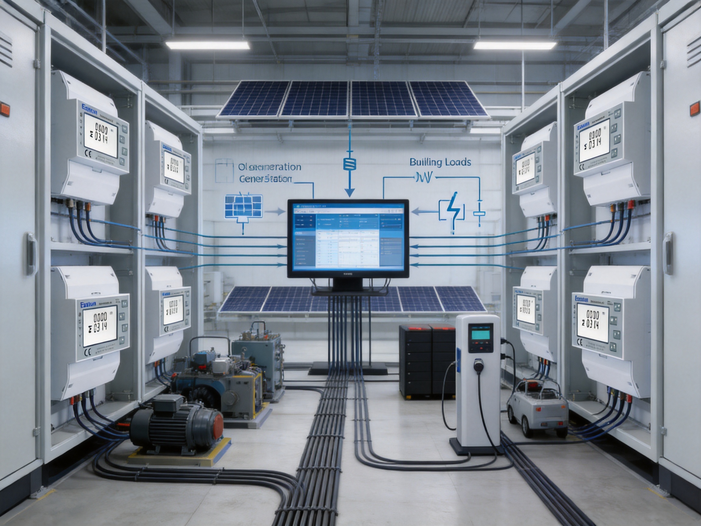
Microgrids often contain several energy paths: utility supply, solar generation, battery storage, backup generation, and local loads. A compact multifunction meter can be deployed at selected points to measure the flow between these elements. Its communication interface can provide data to an energy-management controller that schedules charging, discharging, or load shedding.
Although a complete microgrid normally requires additional protection, control, synchronization, and power-quality equipment, a network of appropriately placed meters provides the measurement foundation for understanding system performance.
The meter can be applied in larger residential buildings, apartment blocks, student housing, and managed properties where individual units or shared services require separate energy records. M-Bus is well suited to installations with multiple meters connected to a common data-collection system. A compact four-module design helps installers fit meters into distribution boards without using an oversized enclosure.
For billing-related applications, project owners should verify the applicable regulatory framework, approval requirements, certification category, and metrological obligations in the target market. A technical energy meter may be suitable for monitoring and allocation, while formal revenue metering may require additional national or regional approvals.
The performance of an energy meter depends not only on its circuit design but also on the consistency of its manufacturing process. High-quality meters require controlled component sourcing, accurate assembly, firmware verification, calibration, electrical safety testing, communication testing, and traceable final inspection. A manufacturer with dedicated engineering and laboratory capabilities can manage these stages more effectively than a supplier that focuses only on basic assembly.
Eastron Electronic Co., Ltd. has developed its business around electricity meters, power analyzers, current sensors, communication modules, and energy-measurement solutions. Its product development and manufacturing activities are supported by teams in China and the United Kingdom, as well as cooperation with universities and technical institutions. This combination contributes to a broader engineering base covering measurement algorithms, embedded systems, hardware design, communications, and application requirements.
Multifunction energy meters require coordination between analog measurement circuits, microprocessors, display systems, communication interfaces, memory, power supplies, firmware, and protective design. Research and development must address accuracy over different load levels, behavior under distorted waveforms, stable energy accumulation, communication reliability, user-interface design, and long-term product availability.
The company’s focus on electricity measurement supports specialization in these areas. Instead of treating metering as a secondary function inside a general-purpose control product, a dedicated energy-measurement manufacturer can develop repeatable design methods for voltage sensing, current measurement, phase calculation, power integration, and energy-register management.
Patented technologies in software, embedded software, and hardware further demonstrate an emphasis on proprietary development. Intellectual-property capability can help a manufacturer refine measurement algorithms, protect product architecture, and respond more quickly to changing requirements in smart metering and energy management.
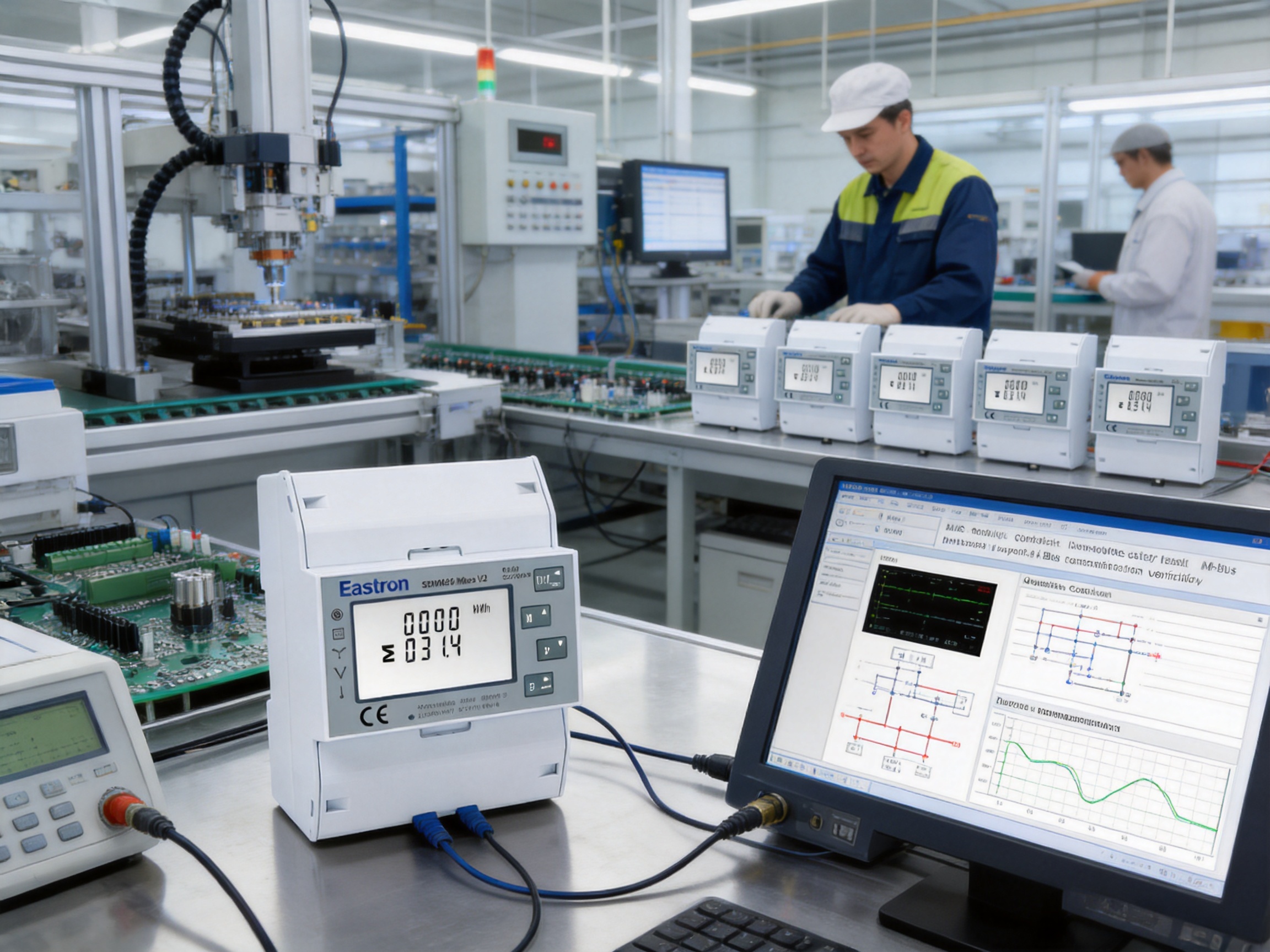
The manufacturer maintains a professional laboratory capable of performing EMC, LVD, accuracy, and environmental tests according to IEC, EN, GB, and UL-related requirements. These test categories are important because a meter must function correctly not only under ideal laboratory conditions but also in the electrically noisy and environmentally variable conditions found in real installations.
Electromagnetic compatibility testing evaluates the product’s ability to resist interference and avoid creating unacceptable emissions. This is particularly important for meters installed near contactors, variable-frequency drives, switching power supplies, inverters, and communication equipment. Low-voltage safety testing examines insulation, dielectric strength, clearances, creepage distances, and other protection measures.
Accuracy testing verifies the measurement results against reference equipment over defined voltage, current, phase angle, frequency, and load conditions. Environmental testing can examine performance under temperature, humidity, and other stresses. Together, these activities provide a structured way to identify design weaknesses before products reach the field.
Laboratory capability also supports product development. Engineers can test prototypes, compare revisions, investigate field-return conditions, and validate improvements without relying entirely on external facilities. This can shorten development cycles and strengthen the feedback loop between design, manufacturing, and quality assurance.
Consistent production requires more than passing a final inspection. It involves controlled bills of materials, approved component suppliers, documented work instructions, operator training, assembly checkpoints, firmware control, calibration procedures, and traceability. Automated or semi-automated production equipment can improve repeatability for printed-circuit-board assembly, soldering, display installation, terminal assembly, and enclosure integration.
For a direct-connected meter, terminal quality is especially important. The current path must withstand the intended electrical load, and the connection structure must remain mechanically stable during service. Production controls should verify terminal alignment, screw or clamp function, conductor access, insulation barriers, and housing integrity.
Electronic assembly quality is equally important. The measurement front end includes components whose tolerances and temperature behavior can affect accuracy. Controlled soldering, inspection, and functional testing help reduce defects that could otherwise appear as intermittent readings, communication failures, display problems, or inaccurate energy accumulation.
Firmware configuration must also be managed carefully. Products with multiple wiring modes, communication options, pulse settings, tariff features, and password-protection functions require accurate software loading and verification. A controlled programming process helps ensure that the delivered meter corresponds to its product variant and that default settings are documented for installers.
The company follows the ISO 9001 quality-management system, which provides a structured framework for documented processes, corrective actions, continuous improvement, customer feedback, and management review. A quality system does not replace product testing, but it helps establish repeatable organizational practices that support reliable manufacturing at scale.
The company’s production has also been approved by SGS according to MID standards. In addition, the product described here is ETL listed by Intertek, supporting its qualification for entry into the American market. Certification and listing details should always be checked against the exact model, variant, intended application, and current certificate scope. Nevertheless, independent assessment provides customers with greater confidence than relying only on an internal statement of conformity.
Before installation, the contractor should confirm the exact model designation, wiring system, rated voltage, maximum current, communication type, pulse-output assignment, and applicable approvals. The SDM630 product family includes several related versions, so model verification is important. The M-Bus variant should not be confused with a Modbus or Ethernet version when preparing a bill of materials.
During installation, the phase and neutral conductors should be connected according to the supplied wiring diagram. The installer should verify that the meter’s input terminals, output terminals, and auxiliary communication terminals are not mixed. The circuit should be isolated before work begins, and all electrical safety procedures should be followed.
After power is applied, the display should be checked for sensible voltage, current, frequency, and power values. If a known load is available, the installer can compare the meter with a reference measurement. Import and export registers should be checked by observing the expected direction of power flow. A reverse reading may indicate reversed phase wiring, an incorrect phase sequence, or an installation arrangement that differs from the intended configuration.
For M-Bus commissioning, each meter should have a unique communication address. The master must use compatible baud rate, parity, and stop-bit settings. A communication survey should confirm that all connected meters respond correctly and that the cable length and topology are suitable for the installation. Clear labeling of meter addresses and physical locations simplifies future maintenance.
Password protection for configuration parameters is useful in shared or managed facilities. Authorized personnel can set the wiring mode, communication parameters, pulse settings, and other available options, after which the configuration can be protected against accidental modification. A commissioning record should document the final settings and retain any passwords according to the site’s access-control policy.
The value of an energy meter increases when its measurements are used to improve decisions. A single meter can provide local visibility, but a group of M-Bus-connected meters can reveal consumption patterns across a complete facility. This supports load benchmarking, tenant allocation, maintenance planning, energy audits, and sustainability reporting.
Centralized data also makes it possible to compare similar circuits. If one motor, floor, pump, or charging station consumes significantly more energy than comparable units, the difference may indicate operating schedules, equipment condition, control settings, or process variation. Current, power factor, and demand data can help narrow the investigation.
Energy measurement also supports verification of improvement projects. After installing efficient lighting, variable-speed drives, insulation, solar generation, or power-factor correction, the meter can provide before-and-after data. Reliable measurement is necessary to distinguish genuine savings from changes caused by weather, occupancy, production volume, or operating hours.
Because the product includes both M-Bus and pulse outputs, it can work within systems of different complexity. Smaller projects may use pulses for a straightforward counter, while larger projects may use M-Bus for detailed reading and historical analysis. This adaptability helps protect the initial equipment investment as monitoring needs expand.
No single meter is ideal for every application. The SDM630-Mbus V2 is designed for direct measurement up to 65 A, so higher-current feeders may require a CT-connected meter or another instrument. The rated voltage and supported wiring arrangements must match the electrical system. Installations with unusual voltage levels, high fault currents, severe environmental exposure, or advanced power-quality requirements should be reviewed by a qualified engineer.
The meter measures RMS electrical quantities including harmonics, but organizations requiring detailed harmonic spectra, transient capture, waveform recording, flicker analysis, or event-triggered power-quality reporting may need a specialized analyzer. The product is best understood as a multifunction energy meter with useful operational measurements rather than as a complete laboratory-grade power-quality recorder.
Communication planning is also essential. M-Bus requires a compatible master or gateway, suitable cable, correct addressing, and coordinated communication settings. If the site’s existing automation infrastructure is based on Modbus RTU, Ethernet Modbus TCP, or another protocol, the project may require a gateway or a different model variant. Confirming the system architecture before purchase avoids compatibility problems.
Finally, formal billing or revenue-metering applications may have regulatory requirements beyond general energy monitoring. The product’s ETL listing and stated IEC classifications are important technical qualifications, but the project owner should confirm whether local authorities require additional approvals, seals, verification procedures, or specific metrological certification.
It is a multifunctional three-phase DIN-rail energy meter with direct current measurement up to 65 A, two pulse outputs, and M-Bus communication according to EN 13757. It measures energy and a range of electrical operating parameters.
Yes. The product information specifies support for 1P2W as well as 3P3W and 3P4W configurations. The meter must be wired and configured for the correct system type before readings are used.
Not for circuits within its direct current capability. The maximum direct current is 65 A. External CTs may still be required for larger feeders or for installations whose electrical design calls for CT-based measurement.
The rated current is 10 A, the maximum current is 65 A, the minimum current is 0.5 A, and the starting current is 40 mA, according to the supplied product information.
The stated rated voltage is 230 V line-to-neutral or 120 V line-to-neutral, with an operational range of 80% to 120% of the rated voltage. The actual installation should be checked against the complete technical documentation and local electrical requirements.
Available measurements include kWh, kVarh, watts, var, VA, power factor, frequency, demand, voltage, and current. The meter also supports bidirectional measurement of imported and exported energy.
Active energy is specified as Class 1.0 according to IEC 62053-21. Reactive energy is specified as Class 2 according to IEC 62053-23.
M-Bus is a meter-oriented communication system commonly used for centralized reading of multiple utility and energy meters. Modbus is a general industrial protocol often implemented over RS485 or Ethernet. The M-Bus version and Modbus versions of the product family are different variants and should not be interchanged without a suitable gateway.
The meter provides two pulse outputs. They can be used for imported and exported energy or assigned according to the available configuration options.
The stated maximum transmission distance is up to 1,000 m under suitable installation conditions. Actual performance depends on cable selection, network topology, master capability, connected devices, electrical noise, and installation quality.
The specified M-Bus address range is 1 to 250, and baud rates range from 300 bps to 9,600 bps. Parity can be none, odd, or even, and stop bits can be one or two, subject to system compatibility.
It can be suitable for many solar and distributed-generation applications because it supports bidirectional energy measurement. The final installation must satisfy the electrical, interconnection, protection, and regulatory requirements of the project.
It is a multifunction energy meter that measures RMS quantities including harmonics and provides useful operational parameters. Applications requiring detailed harmonic spectra, transient capture, waveform recording, or advanced event analysis may need a dedicated power-quality analyzer.
DIN-rail mounting allows the meter to be installed in common distribution boards and control cabinets. Its four-module, 72 mm width helps conserve panel space while providing a front display, local controls, measurement functions, and communication terminals.
The manufacturer has dedicated electricity-measurement development capabilities, a professional laboratory for EMC, LVD, accuracy, and environmental testing, ISO 9001 quality-management practices, and production approvals and certifications associated with international standards and independent assessment organizations.
Suitability depends on the country, utility, metrology rules, contract, and exact product certification. The stated accuracy and listings are important technical information, but the project owner must confirm all local revenue-metering requirements before using the meter for regulated billing.
The SDM630-Mbus V2 combines direct 65 A measurement, multifunction electrical analysis, bidirectional energy recording, pulse outputs, M-Bus communication, and compact DIN-rail installation in one device. Its support for 3P3W, 3P4W, and 1P2W systems gives it broad application potential, while its four-module housing helps it fit into space-constrained distribution boards.
Its principal advantages are practical as well as technical. Direct connection can reduce the need for external CTs on suitable circuits. A wide measurement range provides more insight than a basic kWh counter. M-Bus connectivity supports centralized data collection, and pulse outputs preserve compatibility with simpler monitoring systems. These capabilities make the meter suitable for commercial submetering, small industrial facilities, renewable-energy systems, electric-vehicle charging, microgrids, and multi-tenant buildings.
The product is supported by a manufacturer whose strengths include specialized energy-measurement development, laboratory testing, embedded and hardware engineering, international certification experience, ISO 9001 quality practices, and a broad portfolio of related electrical products. Such manufacturing and engineering capabilities are important when meters are deployed in large quantities or integrated into long-term energy-management programs.
For the best results, buyers and installers should match the exact model to the electrical system, confirm the communication architecture, follow the wiring and safety instructions, document commissioning settings, and verify regulatory requirements for the intended application. When correctly selected and installed, the meter can provide a reliable foundation for energy visibility, operational improvement, and smarter electrical-system management.
IEC 62053-21, Electricity Metering Equipment: Particular Requirements—Static Meters for Active Energy.
IEC 62053-23, Electricity Metering Equipment: Particular Requirements—Static Meters for Reactive Energy.
EN 13757, Communication Systems for Meters and Remote Reading of Meters.
ISO 9001, Quality Management Systems—Requirements.
Intertek ETL Certification and Listing Principles for Electrical Products.
SDM630-Mbus V2 Product Technical Information and Installation Data.
Manufacturer documentation for SDM630 multifunction energy meter variants, communication options, and electrical specifications.
Your email address will not be published. Required fields are marked *

We develop and produce high performance electricity meters, power analyzers, current sensors, communication modules and management systems.
Address:NO. 52, Dongjin Road, Nanhu, Jiaxing, Zhejiang, China
Copyright @ Eastron Electronic Co., Ltd. All rights reserved
