

 English
 Español
 Deutsch
 中文简体


Product Consultation
Your email address will not be published. Required fields are marked *
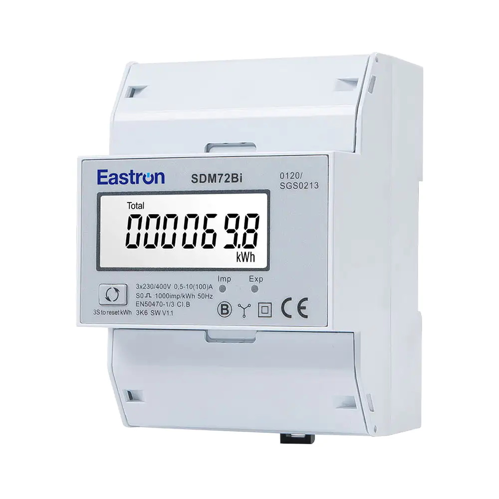
Resettable Bi-directional Din Rail Three Phase Electronic kWh meter with Pulse Output
Aug 11,2022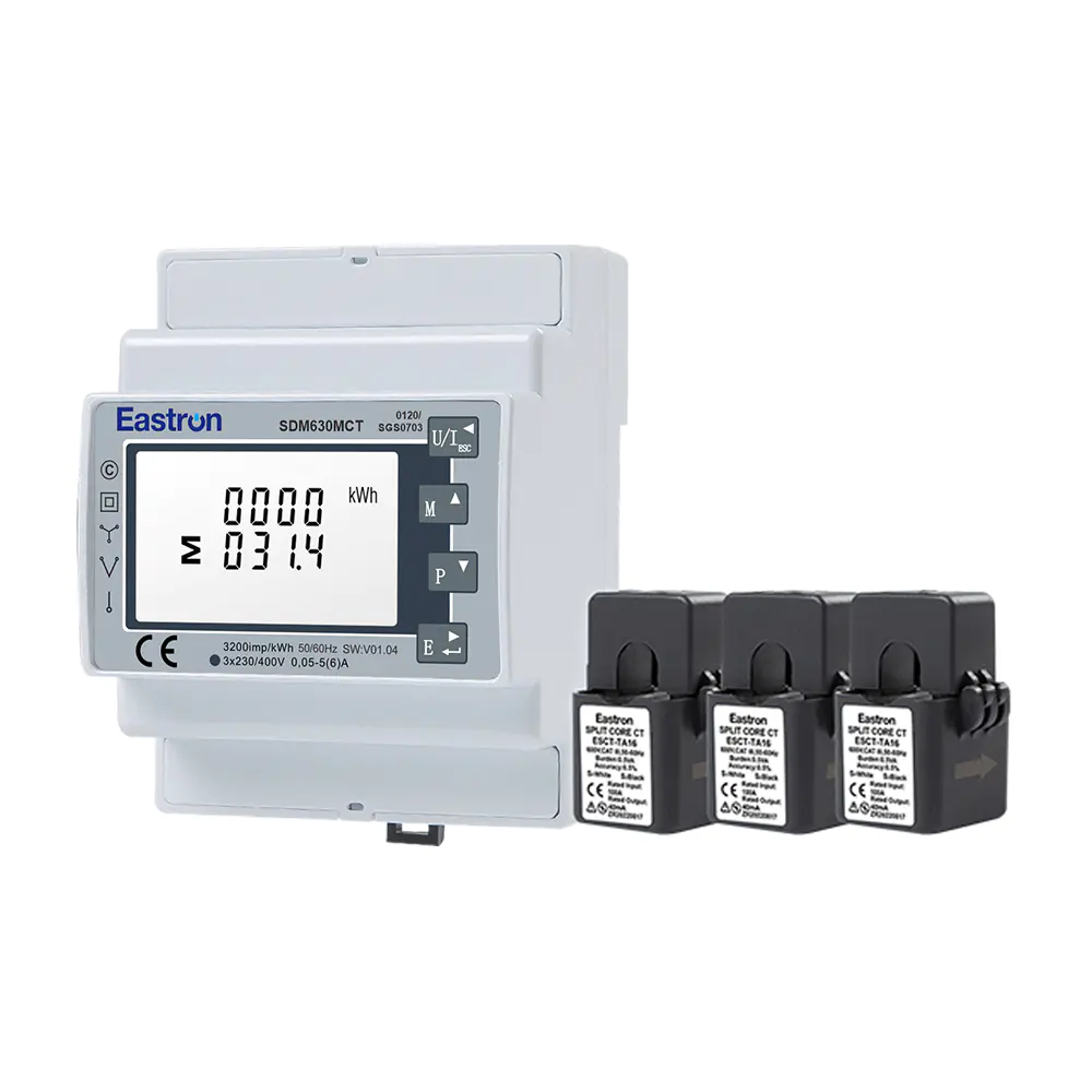
MID/UL CT Type Din Rail Three Phase Multi-function Energy Meter for EV Charging Metering
Nov 24,2022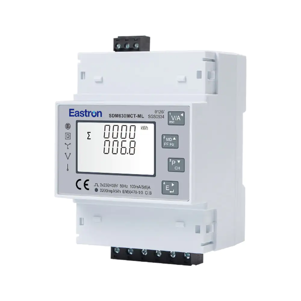
Quad Load Three Phase Multi-function RS485 Energy Meter for Data Center Metering
Aug 03,2022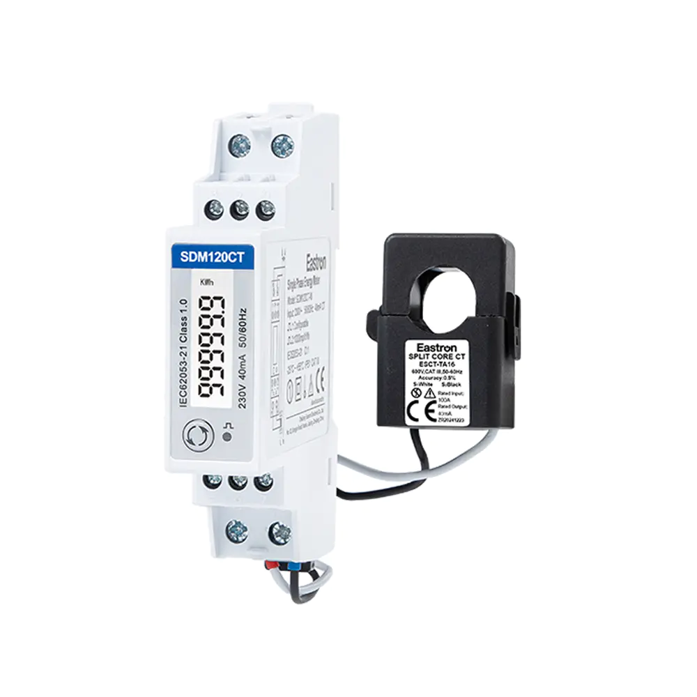
RCM 40mA CT Input Din Rail Single Phase Multi-function Solar PV /Zero Export Meter for PV Metering
Nov 24,2022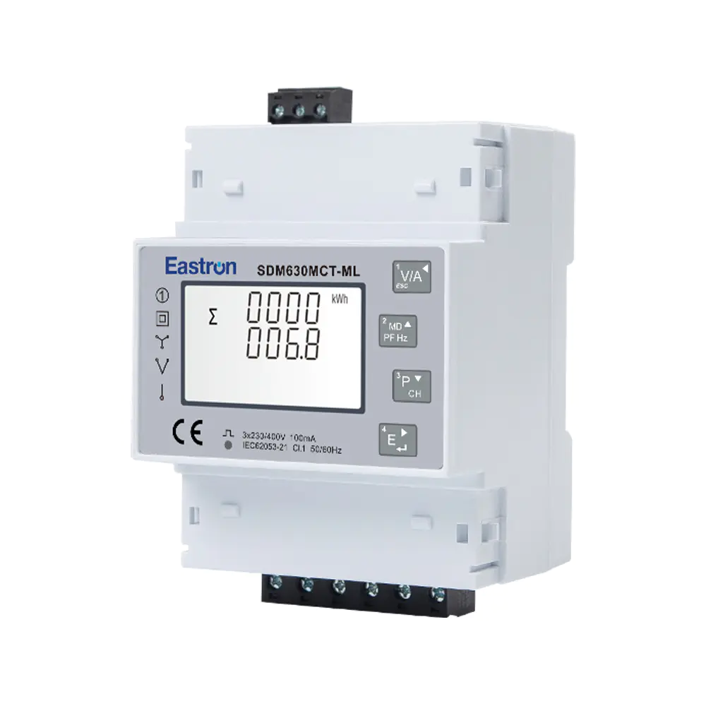
Multi-Circuit Three Phase Ethernet Modbus TCP Energy Meter for Data Center Metering
Aug 03,2022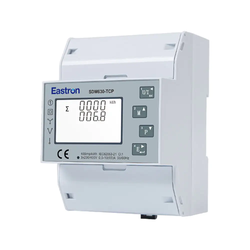
Direct Type Three Phase Ethernet Modbus TCP Energy Meter for Data Center Metering
Nov 24,2022Content
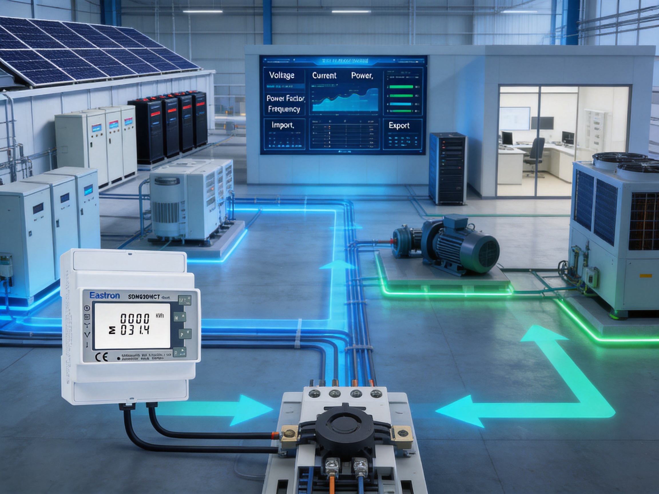
Modern electrical installations require more than a simple total-energy reading. Facility operators, building managers, industrial engineers, renewable-energy developers, and electrical contractors increasingly need a complete view of how power is being consumed, generated, distributed, and controlled. Voltage, current, active power, reactive power, apparent power, power factor, frequency, demand, and imported or exported energy can all influence operating cost, equipment performance, and system reliability.
The SDM630MCT-40mA is a three-phase multifunction energy meter designed for these measurement requirements. It combines current-transformer operation, voltage and power measurement, bidirectional energy registration, pulse outputs, and RS485 Modbus RTU communication in a compact DIN-rail housing. Its support for 3P4W, 3P3W, and 1P2W systems allows it to serve a wide range of electrical applications, from commercial distribution boards and industrial control panels to renewable-energy systems and submetering installations.
With a width of four modules, or 72 mm, the meter offers a practical balance between measurement capability and panel-space efficiency. It is designed to work with 40 mA current-transformer signals while also supporting other specified CT secondary inputs in the product series. This makes it suitable for installations where direct current connection is impractical, where conductors cannot be disconnected, or where measurement must be integrated into an existing distribution system.
The product is manufactured by Eastron Electronic Co., Ltd., a specialist in electricity meters, power analyzers, current sensors, communication modules, and energy-management solutions. The company combines product development, laboratory testing, standards-based manufacturing, and international technical support to provide metering equipment for customers in more than 50 countries.
Electrical energy is rarely used in a perfectly balanced or constant manner. Loads change throughout the day, motors create reactive demand, power electronics introduce waveform distortion, and distributed generation can reverse the direction of energy flow. A meter that reports only accumulated kilowatt-hours cannot provide enough information to explain these changes.
A multifunction meter addresses this limitation by collecting several related electrical parameters through one measurement platform. Operators can use voltage readings to identify supply variation, current readings to observe loading, power-factor values to assess efficiency, and active or reactive power readings to understand the nature of the load. Frequency measurements provide additional information about supply quality, while demand readings can support capacity planning and tariff management.
In a commercial building, the meter may be installed to monitor an HVAC system, tenant distribution board, server room, retail area, or charging installation. In an industrial facility, it can support monitoring of production lines, pumps, compressors, motors, furnaces, and auxiliary equipment. In a solar or storage application, bidirectional measurement helps distinguish energy imported from the grid from energy exported to it.
Centralized access to measurement data also improves maintenance. Abnormal current imbalance, declining power factor, unexpected night-time consumption, or a sudden increase in reactive power may indicate a developing problem. By connecting the meter to a building-management system, supervisory-control platform, or energy-management software, users can move from occasional manual readings to continuous operational awareness.
The SDM630MCT-40mA is a CT- and PT-operated three-phase multifunction energy meter for AC systems. It measures RMS values, including harmonics, on three-phase and three-phase-plus-neutral systems. The unit requires an auxiliary AC or DC power supply for operation, while its measurement inputs are connected through suitable current transformers and voltage connections.
The meter is designed for DIN-rail installation and occupies four modules. This standardized mounting format simplifies installation in electrical enclosures and allows the instrument to be positioned beside protective devices, contactors, communication equipment, and other modular components.
The product includes two pulse outputs and an RS485 interface using Modbus RTU. Pulse outputs can be used for basic energy-pulse collection, connection to pulse counters, or integration with compatible controllers. The RS485 interface provides access to a broader set of real-time and accumulated values, allowing the meter to become part of a larger monitoring network.
| Feature | Specification or Function | Practical Benefit |
|---|---|---|
| Electrical system support | 3P4W, 3P3W, and 1P2W | Suitable for multiple wiring arrangements |
| Current input | CT secondary options including 40 mA | Supports low-level current-transformer signals |
| Voltage input | 230 V L-N or 120 V L-N rated voltage | Adaptable to common low-voltage systems |
| Measurement | Voltage, current, W, var, VA, power factor, frequency, demand, energy, and more | Provides a comprehensive electrical profile |
| Energy direction | Bidirectional measurement | Useful for generation, storage, and import/export applications |
| Communication | RS485 Modbus RTU | Enables connection to monitoring and control systems |
| Pulse outputs | Two pulse outputs | Supports pulse-based data collection |
| Installation | DIN rail, 4 modules, 72 mm wide | Conserves enclosure space |
| Communication distance | Up to 1000 m maximum under suitable conditions | Supports distributed panel networking |
The instrument measures RMS quantities, including harmonics, across a three-phase AC system. RMS measurement is important because many modern loads do not draw smooth sinusoidal current. Variable-speed drives, switching power supplies, LED drivers, uninterruptible power supplies, and information-technology equipment can all affect the waveform.
By measuring under realistic waveform conditions, the meter can provide a more useful representation of system loading than a basic average-reading instrument. This is particularly valuable where the apparent electrical burden of a load differs from its active-power consumption. For example, a facility may have acceptable kilowatt usage but still experience high apparent power because of poor power factor or distorted current.
The specified measurement accuracy includes voltage and current accuracy of ±0.5%, frequency accuracy of ±0.2%, and power-factor accuracy of ±1%. Active, reactive, and apparent power are specified at ±1%. These values support practical energy-management applications in which consistent and traceable measurement is needed for operational decisions, allocation of consumption, and performance comparison.
For active energy, the meter is specified as Class 0.5S under IEC 62053-22 and Class 1.0 under IEC 62053-21. Reactive-energy performance is specified as Class 2 under IEC 62053-23. The appropriate classification depends on the application, installation conditions, and the requirements of the system designer or authority responsible for the measurement.
One of the most distinctive characteristics of this model is its compatibility with a 40 mA current-transformer secondary signal. Conventional meters often use higher secondary currents, while low-level CT systems can be advantageous where compact sensors, safer signal handling, or specialized monitoring arrangements are required.
Current transformers allow the meter to measure large primary currents without placing the full load current directly through the instrument. A CT surrounds or connects to the monitored conductor and produces a reduced secondary signal proportional to the primary current. The meter interprets this signal using the configured CT ratio and calculates the corresponding primary current, power, and energy.
The specified CT-primary range is 1 A to 9999 A. This broad range allows the same metering concept to be applied to relatively small feeders and substantially larger distribution circuits, provided that the selected CTs, voltage system, installation method, and programmed ratio are suitable.
CT operation also supports retrofit installations. In many existing panels, interrupting the main conductor to install a direct-connected meter may require a shutdown or extensive rewiring. A properly selected CT-based arrangement can reduce disruption and simplify the measurement upgrade. Installation must nevertheless be completed by qualified personnel, and CT wiring must follow the sensor manufacturer’s instructions and applicable electrical-safety practices.
Accurate CT measurement depends on correct polarity, phase identification, ratio configuration, burden suitability, and secure termination. The meter provides the calculation platform, but the complete measurement chain includes the primary conductor, CT, voltage connection, wiring, configuration, and communications system. A carefully installed system will deliver considerably better results than one in which the CTs are installed without attention to orientation or phase correspondence.
The meter supports 3P4W, 3P3W, and 1P2W arrangements. This flexibility is important because low-voltage distribution systems are not uniform across all facilities or regions. A four-wire three-phase system with neutral is common in commercial buildings and mixed single-phase and three-phase installations. A three-wire three-phase system is frequently used for balanced industrial loads and motor circuits. Single-phase two-wire measurement is useful for individual circuits, small buildings, and selected submetering applications.
For a 3P4W installation, the instrument measures the three phase-to-neutral voltages and corresponding phase currents. This arrangement is appropriate when phase imbalance, neutral loading, and individual phase consumption need to be observed.
For a 3P3W installation, the meter is configured for a system without a neutral conductor. The voltage and current connections must match the selected wiring mode, and the phase sequence should be checked during commissioning.
For a 1P2W installation, the instrument can be used for a single-phase circuit where the configuration and available inputs are appropriate. This gives system integrators more freedom when standardizing on one meter family across different panels.
Because wiring configuration affects calculation, it should be programmed correctly before readings are interpreted. Incorrect configuration can produce apparently plausible but inaccurate values. Commissioning should therefore include verification of phase voltage, phase current, power direction, total power, and energy accumulation.
Traditional energy meters are often installed with the assumption that energy flows from the utility network to the consumer. Modern systems are more dynamic. Solar photovoltaic inverters, battery energy-storage systems, regenerative drives, microgrids, and backup generators can all cause energy to flow in both directions.
Bidirectional measurement allows the meter to register imported and exported energy according to the configured system arrangement. This capability is useful for determining how much energy a facility purchases from the grid, how much locally generated energy is consumed on site, and how much surplus energy is sent outward.
In a solar installation, the meter can help compare photovoltaic production with building demand. In a battery system, it can help distinguish charging energy from discharging energy. In a tenant or departmental submetering project, it can identify the direction of energy movement between internal distribution sections.
Correct polarity is essential for bidirectional measurement. CT orientation, voltage-phase matching, and the selected energy-direction convention must be checked during commissioning. A reliable installation should verify the sign of active power under a known load before the meter is connected to a permanent reporting or billing process.
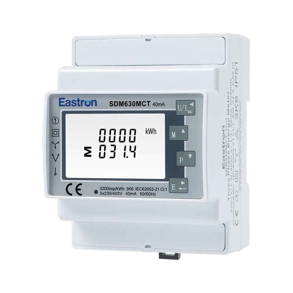
RS485 40mA CT operated Din Rail Three Phase Multi-function Energy Meter
The built-in RS485 interface makes the meter suitable for networked energy monitoring. Rather than requiring a technician to read the instrument locally, a supervisory system can request electrical data from the meter and store it in a database, dashboard, historian, or energy-management platform.
RS485 is widely used in industrial and building-automation environments because it can support multiple devices over a shared communication bus. The SDM630MCT-40mA provides Modbus RTU communication with configurable addresses from 1 to 247. Transmission speeds range from 1200 bps to 38400 bps, with selectable parity and stop-bit settings.
The default parity is none, while odd and even parity are also available. One or two stop bits can be selected to match the host controller. The specified response time is less than 100 milliseconds, allowing the meter to participate in responsive monitoring applications when the network is properly designed.
The maximum transmission distance is specified as 1000 meters. Actual performance depends on cable type, baud rate, grounding, termination, electromagnetic conditions, device count, and network topology. A twisted, shielded cable designed for RS485 communication is generally preferred, and the bus should be installed in accordance with sound industrial-networking practice.
Modbus RTU integration supports several levels of use. A basic installation may read total active energy and display it on a local building-management screen. A more advanced system may collect phase currents, voltages, power factor, active power, reactive power, apparent power, frequency, demand, and directional energy at regular intervals. Historical data can then be used for load profiling, alarm generation, cost analysis, and efficiency reporting.
Each meter on a shared RS485 bus must have a unique communication address. Duplicate addresses can cause data collisions and unreliable readings. The baud rate, parity, and stop-bit settings must also be consistent between the meter and the master device.
Network designers should avoid star-shaped wiring where possible and use a properly arranged bus structure. Termination resistors may be required at the ends of longer networks, while cable shielding and grounding should be considered in relation to the overall control-panel design. Communication cables should be separated from high-voltage power cables when practical, especially in electrically noisy industrial environments.
Before connecting many instruments, it is good practice to test one meter with the intended controller. The installer can confirm the address, serial settings, register map, byte order, scaling, and sign convention before expanding the network. This reduces commissioning time and helps prevent software errors from being mistaken for measurement problems.
The two pulse outputs provide an additional method of collecting energy information. Pulse-based systems remain useful in applications where the control platform does not include a full Modbus driver or where an existing pulse-counter architecture is already installed.
Pulse outputs can be connected to compatible data loggers, counters, programmable logic controllers, or energy-management gateways. The receiving device interprets each pulse according to the configured energy constant and calculates the associated consumption or generation. Pulse connections are particularly practical for simple totalization, remote display, or integration with legacy monitoring equipment.
Having both pulse outputs and RS485 communication gives system designers more than one integration path. Modbus can provide detailed instantaneous values and historical polling, while pulse outputs can supply an independent energy-total signal. In some installations, the two methods can also be used for cross-checking.
Panel space is increasingly valuable. Electrical enclosures may need to accommodate circuit protection, contactors, relays, terminal blocks, surge protection, communication gateways, power supplies, and other control equipment. A meter that offers broad functionality in a four-module, 72 mm housing can help reduce the space required for measurement.
DIN-rail mounting also supports standardized panel construction. Contractors can install the meter using familiar modular techniques, while system integrators can include it in prefabricated control panels and energy-monitoring assemblies. Its compact format is suitable for new installations and for upgrades where space is limited.
A compact housing does not remove the need for adequate clearance, heat management, insulation, and safe access. The enclosure should be selected according to the environment, and wiring should be arranged so that measurement, auxiliary-power, pulse, and communications terminals are clearly identified and protected from accidental interference.
Commercial facilities often contain several energy-consuming zones with different operating schedules. Offices, retail areas, restaurants, common areas, elevators, HVAC systems, and tenant spaces may all require separate monitoring. The meter can provide submetering data without requiring a separate instrument for every individual electrical parameter.
Building managers can use the data to compare weekday and weekend demand, identify after-hours consumption, assess power-factor conditions, and allocate energy usage among departments or tenants. When connected to a central platform, multiple meters can be viewed together to reveal differences between floors, buildings, or operating areas.
Industrial equipment frequently produces changing and uneven electrical loads. Motors may start and stop repeatedly, production lines may operate in cycles, and processes may involve high reactive demand. Measuring current, power, power factor, and demand helps engineers evaluate whether distribution equipment is appropriately sized and whether corrective action may be needed.
The CT-operated design is particularly useful for larger feeders and equipment circuits. The meter can be applied to incoming distribution sections, production areas, motor-control centers, and auxiliary systems, subject to the ratings and installation requirements of the complete electrical system.
Bidirectional measurement is important in photovoltaic, battery, and microgrid applications. The meter can help record the relationship between local generation, on-site consumption, grid import, and grid export. RS485 communication also allows the readings to be incorporated into an energy-management controller or supervisory platform.
In these applications, system designers should pay close attention to the location of the CTs. A meter installed at the point of common coupling will provide different information from one installed on the output of an inverter or on a dedicated building feeder. The measurement location should be selected according to the desired energy balance.
Data centers, communications rooms, and technical facilities require close attention to load continuity and energy performance. Monitoring current, voltage, power factor, and apparent power can help identify capacity constraints and changes in equipment loading. Modbus connectivity enables integration with infrastructure-management platforms that already collect alarms and environmental information.
Utilities, contractors, and facility owners can use the meter in distribution-board upgrades and submetering projects. The broad CT-primary range allows different circuits to be monitored using appropriately selected sensors. Because the meter supports several wiring arrangements, a single product family can be applied across a varied portfolio of panels.
Accuracy is not only a numerical specification; it is also a system property. The performance observed by the end user depends on the meter, current transformers, voltage connections, wiring, configuration, environmental conditions, and verification method.
The SDM630MCT-40mA provides specified accuracy values for voltage, current, frequency, power factor, active power, reactive power, and apparent power. Its active-energy classifications refer to IEC 62053-22 and IEC 62053-21, while reactive-energy classification refers to IEC 62053-23.
These standards provide a structured framework for evaluating energy-meter performance. They help users compare products, define application requirements, and determine whether a particular meter is appropriate for monitoring, internal allocation, performance management, or other purposes.
The product has also been assessed and certified for RCM by SAA, with the stated instrument traceable number SAA220473. Certification and conformity information should always be reviewed against the intended market, installation environment, and current regulatory requirements. Where a project involves revenue settlement or formal legal metrology, the project authority should confirm the applicable approval category before procurement.
The product’s value is supported by the capabilities of its manufacturer. Eastron Electronic Co., Ltd. develops and produces electricity meters, power analyzers, current sensors, communication modules, and energy-management systems. This product breadth provides an important engineering advantage because the company works across measurement hardware, sensing, communications, and system-level applications rather than focusing on only one component.
The company is headquartered in Jiaxing, China, near major economic and technology centers including Shanghai, Hangzhou, and Jiangsu. Its development activities include teams in China and the United Kingdom. This international engineering structure supports product development, application knowledge, and responsiveness to different market requirements.
Research and development is a central part of the company’s manufacturing approach. The organization continues to invest in new metering technologies and products while cooperating with universities and technical institutions. Such cooperation can support improvements in embedded software, measurement algorithms, communications, product design, and application engineering.
The company maintains a professional laboratory capable of performing electromagnetic compatibility, low-voltage, accuracy, and environmental tests. These capabilities are significant because a meter must perform reliably not only under ideal laboratory conditions but also in the electrically noisy and thermally variable environments found in real control panels.
Testing against IEC, EN, GB, and UL-related requirements helps create a disciplined product-development process. EMC testing can identify susceptibility to interference and unwanted emissions. LVD-related evaluation addresses electrical safety considerations. Accuracy testing verifies measurement performance, while environmental testing supports evaluation across relevant operating conditions.
The company also holds patented technologies covering software, embedded software, and hardware. For a modern meter, these areas are closely connected. Hardware establishes the sensing and processing platform, embedded software converts sampled signals into useful electrical values, and external software or communication functions make the information accessible to a wider management system.
Manufacturing quality is supported by an ISO 9001 quality-management system. The company’s production has also been approved by SGS according to MID standards, as stated in the supplied company information. These quality and assessment structures help establish repeatable processes for design control, supplier management, production, inspection, documentation, and corrective action.
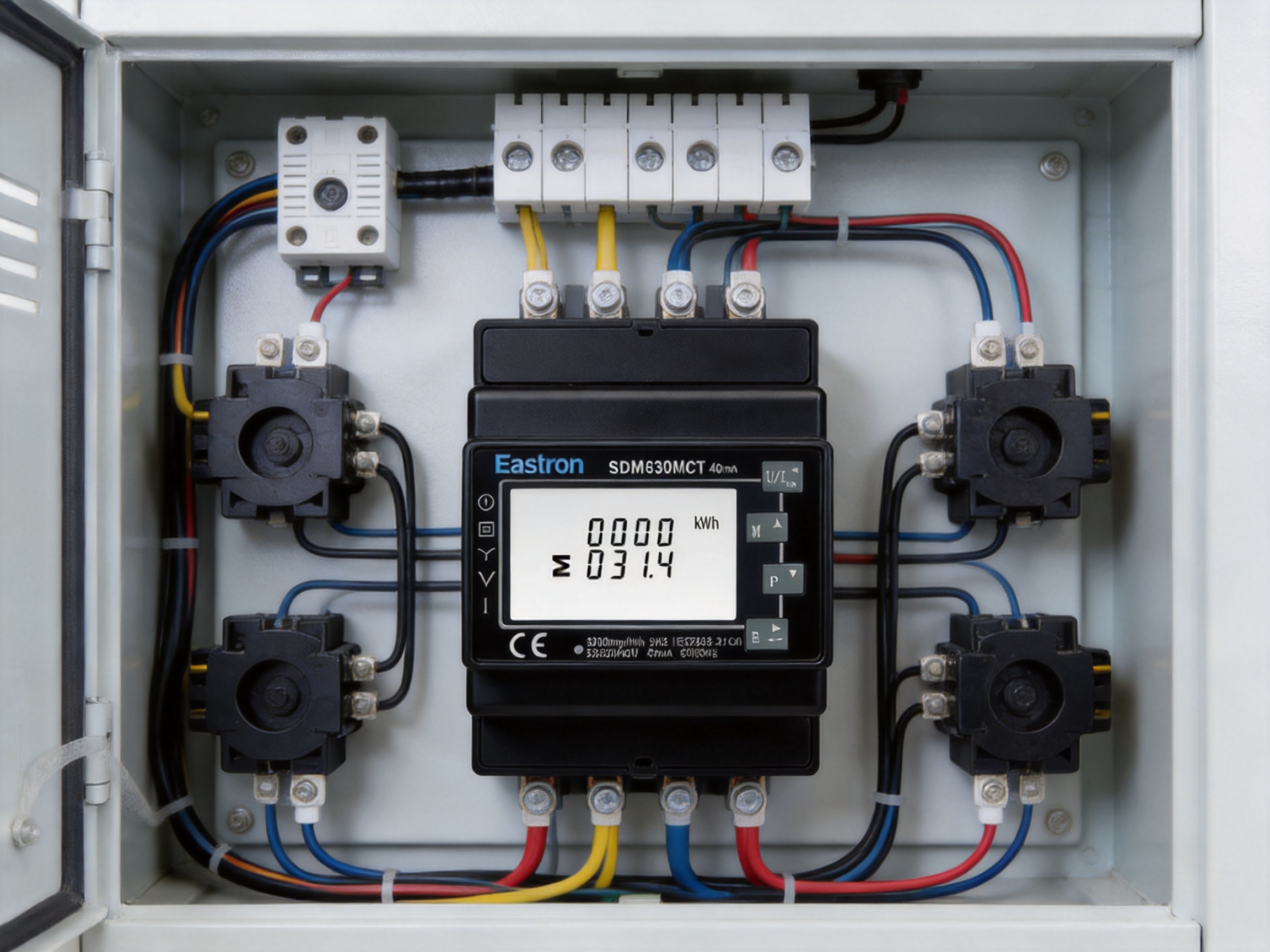
The first advantage is measurement breadth. A simple energy counter may show accumulated kilowatt-hours, while this multifunction meter also provides voltage, current, active power, reactive power, apparent power, power factor, frequency, demand, and related values. This broader data set helps users understand why energy is being consumed rather than merely recording how much has been consumed.
The second advantage is compatibility with low-level CT signals. The 40 mA input option supports applications that are not directly served by conventional direct-connected meters or standard higher-current CT meters. This can improve design flexibility, particularly in retrofit monitoring and systems using specialized current sensors.
The third advantage is wiring flexibility. Support for 3P4W, 3P3W, and 1P2W arrangements allows engineers to select one multifunction meter family for different installation types. Standardization can simplify procurement, training, panel design, spare-parts management, and commissioning procedures.
The fourth advantage is bidirectional measurement. This feature is increasingly important as electrical systems include solar generation, storage, regenerative equipment, and microgrid controls. A meter designed only for one-way consumption may not provide an adequate representation of these installations.
The fifth advantage is communication choice. RS485 Modbus RTU supports detailed digital integration, while dual pulse outputs support simpler or legacy collection methods. This combination gives system integrators more freedom than a meter with only a local display or a single output type.
The sixth advantage is compact installation. A four-module, 72 mm DIN-rail form factor can reduce the enclosure space needed for a multifunction instrument. This is particularly useful in retrofit boards and compact automation panels where available rail length is limited.
Finally, the product is supported by a manufacturer with dedicated laboratory capabilities, a broad energy-measurement portfolio, international development resources, and established quality systems. These strengths can reduce technical risk for distributors, panel builders, contractors, and end users seeking more than a basic commodity meter.
Installation should be carried out by qualified electrical personnel in accordance with local regulations, the meter documentation, and the instructions for the selected current transformers. The auxiliary power supply, voltage inputs, CT secondary circuits, pulse outputs, and RS485 connections should be identified before energization.
The first step is to confirm the electrical system. Determine whether the installation is 3P4W, 3P3W, or 1P2W, verify the nominal voltage, and identify the phase sequence. The selected configuration must match both the physical wiring and the intended measurement method.
The second step is to select compatible current transformers. The CT primary rating should cover the expected operating current without creating unnecessary loss of resolution. The CT secondary signal must match the meter input configuration, including the 40 mA option where applicable. The primary ratio should be programmed accurately.
The third step is to verify CT orientation and phase association. Each CT should be installed on the intended phase, with its polarity marked and aligned according to the wiring diagram. A phase mismatch can create incorrect power readings even if voltage and current values appear normal.
The fourth step is to connect the auxiliary supply and measurement voltage circuits according to the approved diagram. Voltage inputs are measurement connections and should not be treated as interchangeable control terminals. Protective devices and isolation provisions should be selected according to the installation design.
The fifth step is to configure communications. Assign a unique Modbus address, select the required baud rate, parity, and stop bits, and confirm that the host system uses the correct register definitions and data scaling. If pulse outputs are used, confirm the pulse constant and the receiving device’s interpretation.
The final step is functional verification. Compare displayed or communicated voltage and current values with suitable reference instruments, confirm that active power has the expected sign, test energy accumulation, and check that the total value is consistent with the individual phases. Record the configuration for future maintenance.
Measurement becomes more valuable when it is transformed into operational information. A facility can use meter data to establish a baseline, identify peak periods, compare departments, and verify the effect of energy-saving measures.
For example, a site may record electrical demand at regular intervals and compare production output with energy use. If energy intensity increases while production remains stable, engineers can investigate equipment condition, operating schedules, compressed-air losses, or control settings. If power factor declines during certain shifts, the site may evaluate motor loading, capacitor-bank performance, or other reactive-load sources.
Voltage trends can reveal supply variation or phase imbalance. Current trends can indicate overload risk or unexpected equipment operation. Frequency data can support system diagnostics, while reactive and apparent power readings can help explain why a feeder approaches its capacity limit even when active power is moderate.
Bidirectional energy records can also support renewable-energy optimization. A facility may compare self-consumption with export, identify periods of surplus generation, and adjust storage or load schedules. These decisions are more reliable when they are based on synchronized measurements from the correct electrical locations.
Before selecting the meter, users should define the electrical system, expected current range, CT type, nominal voltage, measurement class, installation environment, communications method, and regulatory requirements. The 40 mA version is appropriate when the selected CTs provide the corresponding secondary signal.
Users should also determine whether they need local display access, Modbus data, pulse outputs, or all three. If the meter will be connected to a third-party platform, compatibility should be confirmed in advance, including register addresses, signed values, decimal scaling, energy direction, and accumulated-energy format.
For larger projects, it is advisable to create a standard commissioning sheet. The sheet can include the meter serial number, panel location, CT ratio, wiring mode, Modbus address, communication settings, voltage readings, current readings, power-direction test, and verification date. Consistent documentation improves serviceability when multiple meters are installed.
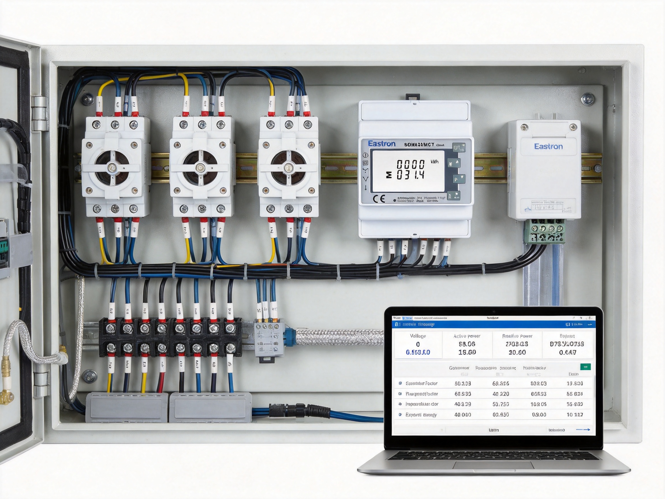
It is a three-phase multifunction energy meter operated through current transformers and voltage connections. It is designed for electrical monitoring and energy measurement in AC systems.
The designation refers to the compatible current-transformer secondary signal. The meter is intended to measure a low-level CT output of 40 mA when configured and connected with suitable sensors.
Yes. The meter provides bidirectional measurement, making it suitable for systems that include solar generation, energy storage, regenerative equipment, or other sources of reverse energy flow.
The meter supports three-phase four-wire, three-phase three-wire, and single-phase two-wire arrangements. The correct wiring mode must be selected and configured during installation.
Yes. The unit requires an auxiliary AC or DC power supply to operate. The auxiliary supply should be connected according to the product documentation and the requirements of the electrical installation.
It uses RS485 with Modbus RTU. The communication address can be set from 1 to 247, transmission speeds range from 1200 bps to 38400 bps, and parity can be set to none, odd, or even.
The meter provides two pulse outputs. These can be connected to compatible counters, controllers, gateways, or other pulse-collection equipment.
Available measurements include kilowatt-hours, kilovar-hours, watts, reactive power, apparent power, power factor, frequency, demand, voltage, current, and related electrical values.
It can be suitable for retrofit projects when the existing system can accommodate compatible CTs, voltage connections, auxiliary power, and the required enclosure space. A qualified engineer should verify the complete installation before work begins.
The meter occupies four DIN modules and is approximately 72 mm wide.
Active-energy performance is specified as Class 0.5S according to IEC 62053-22 and Class 1.0 according to IEC 62053-21. The applicable classification should be considered together with the installation and project requirements.
Multiple meters can generally be connected to a properly designed RS485 bus, provided that each device has a unique address and that wiring, termination, communication settings, and network limits are correctly managed.
The product is manufactured by Eastron Electronic Co., Ltd., a company specializing in electricity meters, power analyzers, current sensors, communication modules, and energy-measurement solutions.
The SDM630MCT-40mA combines flexible electrical measurement, 40 mA CT compatibility, bidirectional energy registration, dual pulse outputs, RS485 Modbus RTU, and compact DIN-rail installation in one multifunction platform. Its ability to support 3P4W, 3P3W, and 1P2W systems makes it adaptable to a broad range of panels and applications.
Compared with basic energy counters, it provides a deeper understanding of electrical performance by measuring voltage, current, power, power factor, frequency, demand, and both active and reactive energy. Compared with meters limited to one-way consumption, its bidirectional capability better reflects modern systems that include distributed generation, storage, and regenerative loads.
The product is also supported by a manufacturer with broad technical expertise, international development resources, professional testing laboratories, patented hardware and software technologies, ISO 9001 quality management, and experience serving customers in many regions. These capabilities strengthen the product’s suitability for professional energy-monitoring projects.
When correctly selected, installed, configured, and commissioned, the meter can provide a dependable foundation for submetering, facility optimization, industrial monitoring, renewable-energy management, and networked electrical supervision. Its combination of measurement depth, communication flexibility, compact construction, and CT-based installation makes it a practical choice for organizations seeking more informed control of electrical energy.
IEC 62053-21, Electricity Metering Equipment: Particular Requirements for Static Meters for Active Energy.
IEC 62053-22, Electricity Metering Equipment: Particular Requirements for Static Meters for Active Energy, Accuracy Classes 0.1S and 0.2S.
IEC 62053-23, Electricity Metering Equipment: Particular Requirements for Static Meters for Reactive Energy.
Modbus Application Protocol Specification, Modbus Organization.
ISO 9001, Quality Management Systems: Requirements.
Product technical information for the SDM630MCT-40mA three-phase multifunction energy meter.
Manufacturer information concerning electricity meters, power analyzers, current sensors, communication modules, testing laboratories, and energy-measurement solutions.
Your email address will not be published. Required fields are marked *

We develop and produce high performance electricity meters, power analyzers, current sensors, communication modules and management systems.
Address:NO. 52, Dongjin Road, Nanhu, Jiaxing, Zhejiang, China
Copyright @ Eastron Electronic Co., Ltd. All rights reserved
